Introduction
We decided to create a virtual archery game for our ECE 4760 final project. This game consists of an ATmega1284P microcontroller, a TV for display, and multiple pieces of hardware. All of these devices communicate together to simulate a three-round game of archery with a target that is 20 feet away from the user.
The ATmega1284P microcontroller uses its internal analog-to-digital converter (ADC) to determine when the stretch sensor has been drawn and released, communicates with an external ADC over SPI to obtain the orientation of the bow from an accelerometer, and displays the expected location of an arrow fired by the user. Another arrow is readied by the push of a button on the bow. When the bow is fully drawn, LEDs will light up simulating the arrow. The lights are turned off when the arrow is released.
This game was inspired by the archery in The Legend of Zelda video games. We wanted to create an archery game that could re-create the fun that we had playing The Legend of Zelda, but that was also safe and convenient.
High Level Design
Rationale and Sources
Archery is a fun sport that we were interested in, but having to carry around and shoot arrows can be unsafe and inconvenient. Finding an appropriate location to practice archery could also difficult and pricey. Virtual archery is a fun way to solve some of these problems. By incorporating the physics of a traveling arrow and knowing the height and distance of a target, a person can simulate the arrow hitting the target. This will allow the person to have some basic practice on how to aim a bow and hit a target.
Since this game was also designed for our culminating design experience (CDE) course, we wanted to incorporate a variety of different topics. We decided to use a stretch sensor to simulate the bow string since it would change resistances based on how far back we stretched it. Creating a voltage divider with this made a simple and effective way to determine the length at which the bow string was stretched. Using the accelerometer also seemed like the simplest way to determine tilt, which was necessary in the calculation of the physics for the system. The TV also had a straight forward RCA connector that would make it easy to connect to and display our target. Since we didn’t have to display any moving objects we knew that flickering would not be a problem. This seemed to make using the TV the most effective solution for a display. After trying to meet our requirements using the most effective and diverse solutions, the layout for our project simply came together.
Background Math
An arrow flying through the air can be modeled as a simple projectile. By defining the center of our coordinate system at the center of our target, it is relatively simple to develop a set of equations to map several input variables into positions on the target. In the vertical direction, we simply start with acceleration due to gravity and integrate twice to find the arrow’s position at any time. In the horizontal direction, we begin with the horizontal component of our initial velocity and integrate once. With both horizontal and vertical positions known in terms of time, we solve for the vertical position in terms of the horizontal position, and then the vertical position at the target.
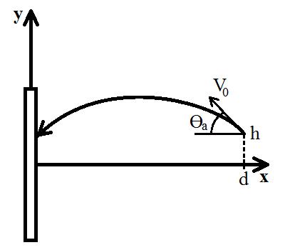
In order to simplify our design, we fixed many of our values. The distance from the target is set to 20 feet, while the height above the center of the target is assumed to be zero. The initial speed of the arrow is then set to 180 feet/s, which appears to be a reasonable speed for an arrow fired from a standard bow. The remaining variable is the initial angle of the bow, which can be determined from the accelerometer.
The purpose of an accelerometer is simply to measure accelerations in one or more directions. Because gravity is a constant acceleration in a constant direction, an accelerometer can easily be used on a stationary object to determine tilt relative to the surface of the Earth. Our accelerometer is set such that it measures 1 g of acceleration when pointing straight down, and 0 g when parallel to the ground. Because this system is circular, the relation between angle and measured acceleration is:
Now that we have derived an equation that can match our measured inputs to our unknown variable, we combine our equations. When we do, the trigonometry cancels out and we end up with:
This equation is now simple enough that, even without fixing many of the values, it could be evaluated in real-time on a microcontroller. However, because our setup calls for only one independent variable, we decided that it was simpler to generate a lookup table of values that fall on the screen. One further layer of math was added during this step to relate the actual reading from our accelerometer to the acceleration, and thus the output. This relationship was determined by our hardware setup and the specifications of our ADC’s datasheet.
In order to draw the target, four concentric circles needed to be drawn. This required us to use the equation of a circle:
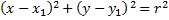
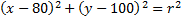
The x1 and y1 terms are used to center the circle around a particular (x,y) coordinate. In this case, the coordinate (80,100) was a good center for our target. The equation is now modified to:
After this, we created a look-up table for all the possible y values within the radius of each circle. This would let us avoid doing slow math, potentially messing up the timing of our TV. The following equations are solved for y:
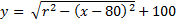
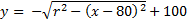
Since we are taking the square root of a value, we need to worry about both the positive and negative values of the equation. These will represent the bottom half and top half of the circle respectively.
Logical Structure
The three major pieces of the archery system were the LCD television, the accelerometer circuit, and the stretch sensor.
In order to function with the LCD television, or in fact any television operating on the NTSC standard, the microcontroller must continually generate a video output. The code to do so is adapted from previous labs performed during ECE 4760. An interrupt is triggered precisely once per video line and the bits to generate the image are sent out of the UART. This code takes up a large portion of the microcontroller’s processing time and prevents other interrupts from being used, which constrains some of the other code needed to run the system.
The accelerometer is a sensor that changes acceleration into a signal that can be used in an electrical domain. Our particular device outputs a voltage that is proportional to the magnitude of the acceleration. To use this acceleration in our program, this voltage had to be converted into a digital form. We chose to use an external ADC for two reasons: 1) the physical distance between the accelerometer and the microcontroller is very large, significantly increasing the potential for noise to corrupt the signal, and 2) the precision of the on-board ADC is only 10 bits. We chose to sample a 13-bit differential ADC, which returns a 2’s compliment value via SPI. The negative input was set to roughly remove the offset of the accelerometer, and the reference was set roughly to Vcc/10 to increase the precision of the measurements.
The stretch sensor is essentialy a large resistor that changes resistance with length. The material is made up of carbon-black impregnated rubber with a resistance of about 350 ohms per inch. Since the stretch sensor is about 1 meter (39 inches) long, the total resistance of the stretch sensor is about 13.65 Kohms. As you stretch out the stretch sensor, the resistance increases linearly – about 350 ohms for every inch that it is stretched out. Once the stretch sensor is released, it takes some time to revert back to its original length. For our purposes, we only needed to wait about a second for the signal to get below our selected threshold.
Other miscellaneous pieces include the LEDs and the button. A bar/dot display driver is used to operate the 10 blue LEDs along the length of the drawback. Future modifications to this design could implement this driver in a way that the bar and/or dot modes are fully utilized – in our design, it is simply used in an on/off mode. The button is a simple pushbutton mounted to the bow. It is debounced in software.
High Level Block Diagram
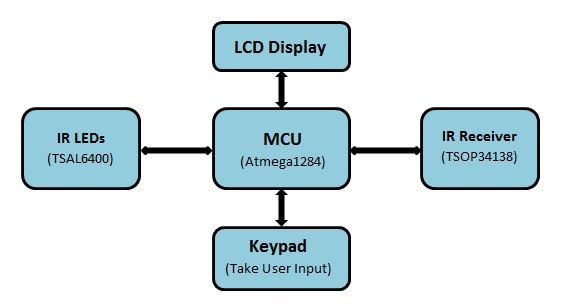
High-level block diagram.
Hardware and Software Trade-offs
There is very little leeway in this project to adjust our hardware versus software usage. The accelerometer output has a low-pass filter in hardware that we further supplement with a low-pass filter in software. Due to the non-ideal properties of the stretch sensor, sensing the draw and release of the bow would be difficult and possibly unreliable in hardware. Debouncing the pushbutton is currently performed in software, though it could theoretically be done using a capacitor. However, hardware and software debouncing are cheap enough that either or both could be used.
Standards
By necessity, video is sent to the LCD TV using the NTSC standard. Due to the limitations of the microcontroller, a much simplified video standard is implemented which only allows points to be drawn.
Communications with the external ADC are governed by SPI communications standards. The ADC is not a true SPI device, though, as it sends but does not receive data.
Intellectual Property (Patents, Copyrights, and Trademarks)
We do not anticipate any potential intellectual property issues.
Video generation code for ATmega property of Bruce Land.
Software Design & Implementation
The important software sections are comparable to the important sections of the system. There is a large section of code dedicated to generating the images on the TV screen, there are methods for getting and interpreting accelerometer values, and there is a state machine for determining when the bow is drawn and released. The state machine for the game is then layered on top of this bow functionality.
Image Generation
Code for video generation has been modified from the ECE 4760 website. The original code can be found here:
Video Generation with Atmel Mega644/1284 and GCC
The main loop and video interrupt have been modified to integrate the state machine for our own project. This extra code was added during the time when nothing is being drawn on the TV screen, after line 251. There was no need to weave any code in between the drawing of each line since our operations were relatively fast.
Accelerometer Interface
Interfacing with the accelerometer is made simpler by the SPI communication hardware built into the microcontroller. By properly setting the SPI control bits, the entirety of SPI communications can be handled with the SPI data register and the SPI status register.
A method is defined purely to send one byte of SPI data. This is used in a function that pulls down the chip select line for a specified device, then gets two full bytes of data from that device. One more function further wraps this, which properly formats the returned integer by extending the 13-bit 2’s compliment value to 16 bits.
Stretch Sensor
After the button has been pressed, the user enters the stage of the game where they can actually draw the sensor, aim at the target, and release the sensor. At this point, the microcontroller’s internal ADC begins taking and converting the voltage from the stretch sensor into digital values. When the stretch sensor is fully drawn, there is a spike in voltage that goes above our set digital threshold of 660. When this threshold is reached, a timer begins to countdown from a second in order to account for the settling time of the stretch sensor to go back down below this threshold.
At the same time, the LEDs connected to the LED driver all light up, indicating that there is a virutal arrow nocked to the bow. After a second has passed, the user has the ability to release the stretch sensor. A similar ADC conversion occurs, with a digital threshold of about 710. Whenever there is a quick change in the amount of pressure along the sensor, the sensor increases rapdily in resistance, causing the voltage to spike. We were able to take advantage of this spike to determine when the sensor is released. After the release of the stretch sensor, the accelerometer is used to calculate where the arrow should have landed and displays its location on the TV. After this, the user can repeat the process of drawing the stretch sensor back, aiming, and then releasing.
Game State Machine
When the game first starts up, a splash screen appears on the LCD TV that explains how to use the bow and the rules of the game. Once the button is pressed, we enter the initial play state. The target appears on the screen, and we begin to sample from the ADCs.
The accelerometer is sampled once per frame. We hold onto the past 8 accelerometer measurements so that when we want to use the accelerometer value, we can average several measurements together to obtain a better estimate of our tilt.
When the internal ADC tells us that the bow has been drawn, we turn the LEDs on and enter a waiting state. As soon as we sense the release of the string, we turn of the LEDs and average the accelerometer readings. We then look up what position the mark should be drawn at based upon the averaged reading. The score associated with this position is added to the total, and the mark is placed.
After the third arrow is fired, a new message appears on the screen prompting the user to press the button to continue. When they do, a screen appears with their score on it. Pressing the button again returns to the initial game state.
Hardware Design & Implementation top
Hardware Overview
There is one major hardware component to our design, and three minor ones. The part requiring the most hardware is the accelerometer circuitry. The minor components, in order of decreasing complexity, are the stretch sensor, the video generator, and the pushbutton. These components were all brought together on a plastic toy bow.
Accelerometer Circuitry
The accelerometer used has a sensitivity of 50mV/g, centered about the middle of the supply voltage. We used the datasheet-recommended low-pass filter to connect the output of the accelerometer to our 13-bit differential ADC. The negative input of the ADC is connected to a voltage divider set to midrange in order to remove the offset from the accelerometer readings. The voltage reference for the ADC is another voltage divider set to roughly divide the voltage rail by ten. This is needed because the accelerometer is designed to sense up to 40 g, while we are only interested in 1 g measurements.
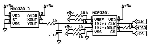
The accelerometer circuitry.
Minor Circuitry
The other three subcircuits used are no more complex than voltage dividers. They are discussed here.
Stretch sensor
The stretch sensor is essentially a rubber band that has been doped with carbon. When it stretches, the distance between the carbon atoms increases, increasing the overall resistance of the sensor. Thus, in the circuit model it is simply a variable resistor. A fixed resistor is used to create a voltage divider that can be used to determine the stretch of the sensor.
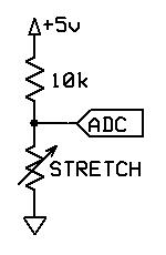
The stretch sensor circuitry.
Video out
There are 3 important voltage levels when generating NTSC video. There is the sync level, at zero volts. This voltage level is used to control the device. There is the black level, at 0.3 volts, which specifies that nothing should be drawn at a certain pixel, and there is the white level at 1 volt, which specifies that a pixel should be white. By attaching two output pins to a voltage divider, these levels can easily be generated.
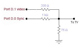
Video output
Pushbutton
The pushbutton is hooked up to an input on the microcontroller with an internal pull-up resistor. It is connected to ground on the other side. When pressed, the voltage at the pin drops to zero volts.
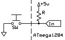
The pushbutton and internal pull-up resistor.
Physical Setup
To enable the simulation of an “arrow”, and to provide a mounting point for the accelerometer, a plastic tube was mounted to the toy bow. A hole was expanded, then the tube was inserted and glued into place. Electrical components are held to the bow with only zip ties. Zip ties are further used to tie together the bundle of wires going to the bow.
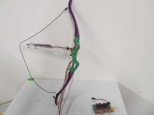
The completed hardware.
Results
Speed
The execution of our program was fairly fast with a few minor exceptions. In order to compensate for the slow settling of the stretch sensor, there was a necessary 1 second delay between the drawing of the bow and the release of the bow added. This shouldn’t be too much of a problem as it typically takes about this long for the user to draw back the bow string, to aim, and to release the bow string. As expected, the TV refreshes at a rate of about 60 Hz without noticeable flickering. Our LEDs also light up/turn off at the right time with no noticeable delays. The timing and order of our game are also right on target with what we wanted.
Safety
In order to enforce safety, we made sure that all of our wires were organized in a way that wouldn’t get in the way of the user, causing them to hit something or trip. Any exposed wire was covered with electrical tape, and the stretch sensor is placed on a notch when not in use, keeping it from moving around.
Interference
There is no real interference with other people’s design since we weren’t using any radio or other wireless communication, nor were we using any infrared LEDs over long distances as originally expected. The brightness of the blue LEDs simulating an arrow may cause some visible light noise at very close ranges, but we don’t expect to be using our project near any other workstations.
Usability
The bow is also very intuitive and easy to use. There is a list of instructions on the start-up screen to explain how to play the game. Our project is intended for people with full functionality of both their arms, as you are required to hold the bow with one hand and pull the bow string with the other. However, with some additional mechanical modifications, it may be possible to play this game if a person has special needs.
Conclusions
Final Thoughts
Towards the end of our time designing our project, we realized that a couple of features that we wanted to add to our project could not feasibly be added in our allotted time frame. We wanted to use infrared in order to determine the distance and position of the bow relative to the target. The first complication was that the math calculations got very complicated and time consuming. Even amidst these calculations, the range that the bow could feasibly sense the infrared LED was just a couple of feet. This was not enough to create an entire archery game. Other than that, we were able to meet the rest of our expectations. We were able to successfully determine the orientation of our bow using the accelerometer and the stretch sensor worked well enough to determine when the bow was being drawn and released. We were also able to display everything correctly on the TV without too many issues with timing.
Next time, we might replace our current stretch sensor with either an accelerometer or perhaps a linear potentiometer. It takes a long time for our current stretch sensor to drop back to its original size after being stretched; this made it seem like our bow is drawn when it really isn’t. This problem was solved adding a second delay between drawing the bow and releasing the arrow. However, an accelerometer could have used the motion of the bow string to accurately determine when it was being pulled. A linear potentiometer attached to our bow string may have also provided a more accurate representation of the amount the bow string was pulled back. This would have solely depended on the position of the draw string as opposed to its elongation. With more time, we may have also implemented a camera to sense the location of the target. In this case, we would have three indicators on the target. We could have used the distance between each indicator as seen by the camera in order to determine how far we were from the target. The absolute location of the indicators would then be used to determine our tilt.
Conforming to Standards
One standard that was used was SPI for the communication between the microcontroller and the external ADC. The only thing different that the standard SPI was that there was no MOSI line connected to the ADC. Since the ADC did not have any memory, there was no way to write to it. The ADC instead relied on the clock supplied by the microcontroller to send its data. The normal MISO line was connected to the microcontroller from the ADC. In this case, there was only one slave; therefore, only one chip select line was needed. The only other standard that was used was NTSC. The main difference between this standard and what we used was the type of scanning we used. We used progressive scanning, so every line of each frame was drawn in sequence. The standard calls for interlace scanning, which is writing to every other odd line in a frame, then coming back to fill in the remaining even lines in the frame. This allows the TV to appear to have a refresh rate that is twice as great as it actually is, which was not necessary for our project.
Intellectual Property Considerations
There really aren’t any intellectual property considerations for this project. The only code that we used was the TV code from the ECE 4760 website, which is in the public domain. However, we did give credit to the users who developed the code in the form of comments at the beginning of our program. We did not reverse-engineer a design, so there were not patent/trademark issues to deal with. We also did not have to sign a non-disclosure to sample any parts. There really aren’t any patent opportunities for our project, making it difficult to justify publication.
Ethical Considerations
There were a couple of considerations to be made concerning the IEEE Code of Ethics. During the design of our project, we made sure that the user will be free of any injuries. There are no high voltage/current sources that could hurt a person using our project. The only moving component, the stretch sensor, was also quite soft, making it extremely difficult for someone to hurt themselves using it. We gave credit when using the code from the ECE 4760 website in order to prevent any perceived conflicts of interests. When stating our lists of cost estimates, we were accurate and honest, not concealing any potential costs that we know of. We were also quite self- critical of our own design, accepting honest criticism of our work to help us improve. Of course, we are not biased towards anyone based on any factors, such as race, religion, and national origins. We understand that some people with physical disabilities may have some trouble using our project, but we tried to make it as accessible as possible given our criteria. Helping our other colleagues was also always an option as our end goal was to learn as much as possible from all our available sources. Helping others not only helps our colleagues grow, but ourselves as well. Overall, we honestly tried to create the best project that we could given our time constraints, and we were honest with others and ourselves throughout the process.
Source: Virtual Archery