Quantcast
Channel: AVR ATmega Projects Archives - Projects Tutorials Code Library for Atmels Atmega32 AVR
Viewing all 1082 articles
Browse latest View live

Making a LED Message Display with Keyboard Interface

$
0
0

LED signage has become the choice in modern days to convey message to visitors of a venue. Be it corporate office, shops, restaurants or any kind of social functions like marriages. Some big and complicated display needs dedicated control PCs and designers to build contents for them. But for simple requirements a very low cost […]

The post Making a LED Message Display with Keyboard Interface appeared first on ATMega32 AVR.


Fastest Finger First Quiz Project using ATmega16

$
0
0

Most of you must have watched quiz games in TV shows or at your schools where few contestants are required to press a switch if they know the answer to the question. An electronic system is required to find out exactly which one of then pressed the button first. This type of electronic system can […]

The post Fastest Finger First Quiz Project using ATmega16 appeared first on ATMega32 AVR.

An AVR microcontroller based Ethernet device

$
0
0

Ethernet has traditionally been a quite complex interface. All Ethernet chips until today had 100 pins or more, where difficult to find in small quantities and difficult to use from a small microcontroller with little memory. Microchip has changed the world with their new ENC28J60 Ethernet chip! The ENC28J60 is a small chip with 28 […]

The post An AVR microcontroller based Ethernet device appeared first on ATMega32 AVR.

Introduction to Arduino UNO (uses AVR ATmega328)

$
0
0

Overview Arduino is an Open Source embedded development platform which is easy-to-use. It comprises of Hardware boards and Software tools. Examples of some of the most popular Arduino Hardware boards are , Arduino Uno This board is designed around the ATmega328 AVR microcontroller. It is an 8 bit microcontroller with 32KB of flash, 2KB of […]

The post Introduction to Arduino UNO (uses AVR ATmega328) appeared first on ATMega32 AVR.

Make your own AVR JTAG debugger

$
0
0

Tired of putting LEDs every time you want to check some value in the microcontroller? Well, its time to build yourself a debugger. A debugger is a device which helps you run through your code in the microcontroller step by step and also gives you the ability to read or write the registers directly using […]

The post Make your own AVR JTAG debugger appeared first on ATMega32 AVR.

How to drive 595 shift registers with AVR hardware SPI

$
0
0

Driving a shift register using an AVR chip’s built-in hardware is really quite easy. Most of their offerings have an SPI module, or Serial Peripheral Interface. A shift register is exactly that, a peripheral device that communicates via a serial line. All we need to do is hook up our connections and use a few […]

The post How to drive 595 shift registers with AVR hardware SPI appeared first on ATMega32 AVR.

How to make an Arduino Pro Mini bare bones with Real-time Clock

Analogue to Digital Conversion on an ATmega168

$
0
0

Many AVR microcontrollers are capable of doing Analogue to Digital Conversion. The ATmega168 has 6 ports (8 ports on the SMD packages) that can be used for analogue input. This tutorial shows you how. The circuit The Breadboard layout is based on the Atmega8 breadboard circuit which is described in Atmega8 breadboard circuit Part 1 […]

The post Analogue to Digital Conversion on an ATmega168 appeared first on ATMega32 AVR.


PIR motion sensor interface with AVR-microcontroller ATMEGA32

$
0
0

Passive Infra red sensor also known as PIR sensors is capable of detecting motion or movement within a certain range. These type of sensors have wide range of applications in our daily life and it is essential to learn the interfacing method. This article is going to demonstrate the PIR motion sensor interface with AVR […]

The post PIR motion sensor interface with AVR-microcontroller ATMEGA32 appeared first on ATMega32 AVR.

Input Devices

$
0
0

Measure something: add a sensor to a microcontroller board that you have designed and read it. This week I decided to make ATMEGA 328 board. ATMEGA 328 Some of the Features of ATMEGA 328 are 1.8-5.5V operating range Up to 20MHz 32kB Flash program memory 1kB EEPROM 2kB Internal SRAM Two 8-bit Timer/Counters One 16-bit […]

The post Input Devices appeared first on ATMega32 AVR.

The simplest digital voltmeter with AVR

$
0
0

This is probably the simplest possible digital voltmeter with Atmel AVR microcontroller. The circuit is controlled by a microprocessor IO1 – Atmel AVR ATmega8 (ATmega8, ATmega8L), a program to download and configuration bits setting is below. (ATmega8 may seem too “big”, but was chosen because it is one of the most frequently used AVR and […]

The post The simplest digital voltmeter with AVR appeared first on ATMega32 AVR.

Configuring and using XBEE wireless modules

$
0
0

Xbees are some of the most powerful wireless modules you can find and they’re also very easy to configure and use. The only thing is they cost about Rs.1000 to Rs.2500 depending on the range and other parameters. If you’re like me and only bought the modules without the breakout boards or forgot to buy […]

The post Configuring and using XBEE wireless modules appeared first on ATMega32 AVR.

Nokia5110 graphical display interfacing with AVR ATmega16/ATmega32

$
0
0

Introduction Nokia5110 is a graphical display that can display text, images and various patterns. It has a resolution of 48×84 and comes with a backlight. It uses SPI communication to communicate with a microcontroller. Data and commands can be sent through microcontroller to the display to control the display output. It has 8 pins. For […]

The post Nokia5110 graphical display interfacing with AVR ATmega16/ATmega32 appeared first on ATMega32 AVR.

Micro-controller Programming on a Bread Board

$
0
0

In playing around with DIY electronics, Pugs has developed enough confidence to share his knowledge with his juniors. So, in one such occasion, he decided to give a try to program a micro-controller, as part of the electronics hobby club. There have been many hobbyist micro-controllers, like 8051, PIC, AVR, … and an equivalent or […]

The post Micro-controller Programming on a Bread Board appeared first on ATMega32 AVR.

100mA Ammeter using AVR Microcontroller

$
0
0

In this project we are going to make a low range ammeter using ATMEGA8 microcontroller. In ATMEGA8, we are going use 10bit ADC (Analog to Digital Conversion) feature to do this. Although we have few other ways to get the current parameter from a circuit, we are going to use resistive drop method, because it’s the easiest and simplest way to get current parameter.

100mA Ammeter using AVR Microcontroller

Digital Ammeter using AVR Microcontroller

In this method we are going to pass the current which needed to be measured in to a small resistance, by this we get a drop across that resistance which is related to current flowing through it. This voltage across resistance is fed to ATMEGA8 for ADC conversion. With that we will have the current in digital value which will be displayed on a 16×2 LCD.

For that we are going to use a voltage divider circuit. We are going to fed the current through the complete resistance branch. The midpoint of branch is taken to measurement. When current changes there will be drop change in the resistance which is linear to it. So with this we have a voltage which changes with linearity.

Now important thing to note here is, the input taken by the controller for ADC conversion is as low as 50µAmp. This loading effect of resistance based voltage divider is important as the current drawn from Vout of voltage divider increases the error percentage increases, for now we need not worry about loading effect.

Components Required

Hardware: ATMEGA8, power supply (5v), AVR-ISP PROGRAMMER, JHD_162ALCD (16*2LCD), 100uF capacitor, 100nF capacitor (4 pieces), 100Ω resistor (7 pieces) or 2.5Ω (2 pieces), 100KΩ resistor.

Software: Atmel studio 6.1, progisp or flash magic.

Circuit Diagram and Working Explanation Schematic 100mA Ammeter using AVR Microcontroller

[See this tutorial to understand how to interface LCD with AVR Microcontroller]

The voltage across R2 and R4 is not completely linear; it will be a noisy one. To filter out the noise, capacitors are placed across each resistor in the divider circuit as shown in figure.

In ATMEGA8, we can give Analog input to any of FOUR channels of PORTC, it doesn’t matter which channel we choose as all are same. We are going to choose channel 0 or PIN0 of PORTC. In ATMEGA8, the ADC is of 10 bit resolution, so the controller can detect a minimum change of Vref/2^10, so if the reference voltage is 5V we get a digital output increment for every 5/2^10 = 5mV. So for every 5mV increment in the input we will have a increment of one at digital output.

For more detail: 100mA Ammeter using AVR Microcontroller


Joystick Interfacing with AVR Microcontroller

$
0
0

In this tutorial we are going to interface a joystick module with atmega8 microcontroller. A JOY STICK is an input module used for communication. It basically makes easy the user machine communication. A joystick is shown in below figure.

Joystick Interfacing with AVR Microcontroller

Joystick Interfacing with AVR Microcontroller

The joystick module has two axis – one is horizontal and other is vertical. Each axis of joystick is mounted to a potentiometer or pot or variable resistance.  The mid points are brought down as Rx and Ry. These pins carry as output signal pins for JOYSTICK.  When the stick is moved along horizontal axis , with the supply voltage present , the voltage at Rx pin changes.

The voltage at Rx increases when moved forward, the voltage at Rx pin decreases when moved backward. Similarly, the voltage at Ry increases when moved upward, the voltage at Ry pin decreases when moved downward.

So we have four directions of JOYSTICK on two ADC channels. At normal cases we have 1Volt on each pin under normal circumstances. When the stick is moved the voltage on each pin goes high or low depending on direction. So four directions as ( 0V,5V on channel 0) for x- axis; ( 0V,5V on channel 1) for y- axis.

We are going to use two ADC channels of ATMEGA8 to do the job. We are going to use channel 0 and channel 1.

Components Required

Hardware: ATMEGA8, power supply (5v), AVR-ISP PROGRAMMER, LED (4 pieces), 1000uF capacitor, 100nF capacitor (5 pieces), 1KΩ resistor (6 pieces).

Software: Atmel studio 6.1, progisp or flash magic.

Circuit Diagram and Working ExplanationSchematic Joystick Interfacing with AVR Microcontroller

The voltage across JOYSTICK is not completely linear; it will be a noisy one. To filter out the noise a capacitors are placed across each resistor in the circuit as shown in figure.

As shown in figure there are four LEDs in the circuit. Each LED represents each direction of JOYSTICK. When the stick is moved in a direction, then the corresponding LED glows.

Before going any further we need to talk about ADC of ATMEGA8,

In ATMEGA8, we can give Analog input to any of FOUR channels of PORTC, it doesn’t matter which channel we choose as all are same, we are going to choose channel 0 or PIN0 of PORTC.

In ATMEGA8, the ADC is of 10 bit resolution, so the controller can detect a sense a minimum change of Vref/2^10, so if the reference voltage is 5V we get a digital output increment for every 5/2^10 = 5mV. So for every 5mV increment in the input we will have a increment of one at digital output.

For more detail: Joystick Interfacing with AVR Microcontroller

4×4 Keypad Interfacing with ATmega32 Microcontroller

$
0
0

In this tutorial we are going to interface a 4×4 (16 key) keypad with ATMEGA32A microcontroller. We know that keypad is one of the most important input devices used in electronics projects. Keypad is one of the easiest ways to give commands or instructions to an electronic system.

4x4 Keypad Interfacing with ATmega32 Microcontroller

4×4 Keypad Interfacing with AVR Microcontroller (ATmega32)

Components Required

Hardware: ATMEGA32, power supply (5v), AVR-ISP PROGRAMMER, JHD_162ALCD (16*2LCD), 100uF capacitor, 100nF capacitor, 10KΩ resistor (8 pieces).

Software: Atmel studio 6.1 or Atmel studio 6.2, progisp or flash magic.

Circuit Diagram and Working ExplanationSchematic 4x4 Keypad Interfacing with ATmega32 Microcontroller

In circuit PORTB of ATMEGA32 is connected to data port LCD. Here one should remember to disable the JTAG communication in PORTC ot ATMEGA by changing the fuse bytes, if one wants to use the PORTC as a normal communication port. In 16×2 LCD there are 16 pins over all if there is a back light, if there is no back light there will be 14 pins. One can power or leave the back light pins. Now in the 14 pins there are 8 data pins (7-14 or D0-D7), 2 power supply pins (1&2 or VSS&VDD or gnd&+5v), 3rd pin for contrast control (VEE-controls how thick the characters should be shown), and 3 control pins (RS&RW&E).

In the circuit, you can observe that I have only took two control pins , this give the flexibility, the contrast bit and READ/WRITE are not often used so they can be shorted to ground. This puts LCD in highest contrast and read mode. We just need to control ENABLE and RS pins to send characters and data accordingly.

The connections which are done for LCD are given below:

PIN1 or VSS to ground

PIN2 or VDD or VCC to +5v power

PIN3 or VEE to ground (gives maximum contrast best for a beginner)

PIN4 or RS (Register Selection) to PD6 of uC

PIN5 or RW (Read/Write) to ground (puts LCD in read mode eases the communication for user)

PIN6 or E (Enable) to PD5 of uC

PIN7 or D0 to PB0 of uC

PIN8 or D1 to PB1 of uC

PIN9 or D2 to PB2 of uC

PIN10 or D3 to PB3 of uC

PIN11 or D4 to PB4 of uC

PIN12 or D5 to PB5 of uC

PIN13 or D6 to PB6 of uC

PIN14 or D7to PB7 of uC

In the circuit you can see that we have used 8bit communication (D0-D7) however this is not a compulsory, we can use 4bit communication (D4-D7) but with 4 bit communication program becomes a bit complex. So from mere observation of above table we are connecting 10 pins of LCD to controller in which 8 pins are data pins and 2 pins for control.

 For more detail: 4×4 Keypad Interfacing with ATmega32 Microcontroller

RFID Based Voting Machine

$
0
0

We know in offices, shopping malls and in many other places where only the person with authorization card is allowed to enter the room. These systems use RFID communication system. RFID is used in shopping malls to stop theft as the products are tagged with RFID chip and when a person leaves the building with the RFID chip an alarm is raised automatically. The RFID tag is designed as small as part of sand. The RFID authentication systems are easy to design and are cheap in cost. Some schools and colleges nowadays use RFID based attendance systems.

RFID Based Voting Machine

RFID Based Voting Machine using AVR Microcontroller

In this project we are going to design a voting machine which only counts authenticated votes. This is done by using RFID (Radio Frequency Identification) tags.  Here we are going to write a program for ATMEGA for allowing only authorized RFID tag holders to vote. (Also check this simple voting machine project)

Components Required

Hardware: ATMEGA32, power supply (5v), AVR-ISP PROGRAMMER, JHD_162ALCD (16x2LCD), 100uF capacitor (connected across power supply), button (five pieces), 10KΩ resistor (five pieces), 100nF capacitor (five pieces), LED (two pieces), EM-18(RFID reader module).

Software: Atmel studio 6.1, progisp or flash magic.

Circuit Diagram and ExplanationSchematic RFID Based Voting Machine

In circuit PORTA of ATMEGA32 is connected to data port of LCD. Here one should remember to disable the JTAG communication in PORTC to ATMEGA by changing the fuse bytes, if one wants to use the PORTC as a normal communication port. In 16×2 LCD there are 16 pins overall if there is a black light, if there is no back light there will be 14 pins. One can power or leave the back light pins. Now in the 14 pins there are 8 data pins (7-14 or D0-D7), 2 power supply pins (1&2 or VSS&VDD or gnd&+5v), 3rd pin for contrast control (VEE-controls how thick the characters should be shown), 3 control pins (RS&RW&E)

In the circuit, you can observe that I have only took two control pins, this give the flexibility of better understanding, the contrast bit and READ/WRITE are not often used so they can be shorted to ground. This puts LCD in highest contrast and read mode. We just need to control ENABLE and RS pins to send characters and data accordingly.

The connections which are done for LCD are given below:

PIN1 or VSS to ground

PIN2 or VDD or VCC to +5v power

PIN3 or VEE to ground (gives maximum contrast best for a beginner)

PIN4 or RS (Register Selection) to PD6 of uC

PIN5 or RW (Read/Write) to ground (puts LCD in read mode eases the communication for user)

PIN6 or E (Enable) to PD5 of uC

PIN7 or D0 to PA0 of uC

PIN8 or D1 to PA1 of uC

PIN9 or D2 to PA2 of uC

PIN10 or D3 to PA3 of uC

PIN11 or D4 to PA4 of uC

PIN12 or D5 to PA5 of uC

PIN13 or D6 to PA6 of uC

PIN14 or D7 to PA7 of uC

In the circuit, you can see we have used 8bit communication (D0-D7). However this is not a compulsory and we can use 4bit communication (D4-D7) but with 4 bit communication program becomes a bit complex, so I preferred 8 bit communication.

So from mere observation of above table we are connecting 10 pins of LCD to controller in which 8 pins are data pins and 2 pins for control.

Before moving ahead, we need to understand about the serial communication. The RFID module here sends data to the controller in serial. It has other mode of communication but for easy communication we are choosing RS232. The RS232 pin of module is connected to RXD pin of ATMEGA.

 For more detail: RFID Based Voting Machine

RFID Based Toll Plaza System

$
0
0

We know in offices, shopping malls and in many other places where only the person with authorization card is allowed to enter the room. These systems use RFID communication system. RFID is used in shopping malls to stop theft as the products are tagged with RFID chip and when a person leaves the building with the RFID chip an alarm is raised automatically. The RFID tag is designed as small as part of sand. The RFID authentication systems are easy to design and are cheap in cost. Some schools and colleges nowadays use RFID based attendance systems.

RFID Based Toll Plaza System

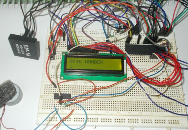
RFID Based Toll Plaza System using AVR Microcontroller

In this project we are going to design a RFID based toll plaza system for security purposes. So this system open gates and allow people only with the authorized RFID tags. The authorized tags holder ID’s are programmed in to the ATMEGA Microcontroller and only those holders are allowed to leave or enter the premises.

Components Required

Hardware: ATmega32 microcontroller, power supply (5v), AVR-ISP Programmer, JHD_162ALCD (16×2 LCD module), 100uF capacitor (connected across power supply), button, 10KΩ resistor, 100nF capacitor, LED (two pieces), EM-18 (RFID reader module), L293D motor driver IC, 5V DC motor.

Software: Atmel studio 6.1, progisp or flash magic.

Circuit Diagram and Working ExplanationSchematic RFID Based Toll Plaza System

In the toll plaza circuit shown above, PORTA of ATMEGA32 is connected to data port of LCD. Here we should remember to disable the JTAG communication in PORTC to ATMEGA by changing the fuse bytes, if we wans to use the PORTC as a normal communication port. In 16×2 LCD, there are 16 pins over all if there is a back light, if there is no back light there will be 14 pins. We can power or leave the back light pins. Now in the 14 pins there are 8 data pins (7-14 or D0-D7), 2 power supply pins (1&2 or VSS & VDD or gnd & +5v), 3rd pin for contrast control (VEE-controls how thick the characters should be shown), 3 control pins (RS & RW & E).

In the circuit, you can observe that I have only took two control pins. This gives the flexibility of better understanding. The contrast bit and READ/WRITE are not often used so they can be shorted to ground. This puts LCD in highest contrast and read mode. We just need to control ENABLE and RS pins to send characters and data accordingly.

The connections which are made for LCD, are given below:

PIN1 or VSS to ground

PIN2 or VDD or VCC to +5v power

PIN3 or VEE to ground (gives maximum contrast best for a beginner)

PIN4 or RS (Register Selection) to PD6 of MCU

PIN5 or RW (Read/Write) to ground (puts LCD in read mode eases the communication for user)

PIN6 or E (Enable) to PD5 of Microcontroller

PIN7 or D0 to PA0

PIN8 or D1 to PA1

PIN9 or D2 to PA2

PIN10 or D3 to PA3

PIN11 or D4 to PA4

PIN12 or D5 to PA5

PIN13 or D6 to PA6

PIN14 or D7 to PA7

In the circuit, you can see we have used 8bit communication (D0-D7). However this is not a compulsory and we can use 4bit communication (D4-D7) but with 4 bit communication program becomes a bit complex, so I preferred 8 bit communication.

So from mere observation of above table we are connecting 10 pins of LCD to controller in which 8 pins are data pins and 2 pins for control.

Before moving ahead, we need to understand about the serial communication. The RFID module here sends data to the controller in serial. It has other mode of communication but for easy communication we are choosing RS232. The RS232 pin of module is connected to RXD pin of ATMEGA.

For more detail: RFID Based Toll Plaza System

Microcontroller Based Electronic Voting Machine

$
0
0

Whenever we go to vote for elections we come to see electronic voting machines. In this project we are going to design and develop a simple voting machine by using ATmega32A microcontroller. Although we can use the controller to get more than 32 people voting machine, to keep everything simple we are going to make a voting machine for a size of four people.We will have four buttons for four people and whenever a button is pressed, a vote goes for the corresponding person and the number of votes each person gets shown on LCD.

Microcontroller Based Electronic Voting Machine

AVR Microcontroller Based Electronic Voting Machine

Components Required

Hardware:

ATMEGA32

Power supply (5v)

AVR-ISP PROGRAMMER

JHD_162ALCD (16×2 LCD)

100nF capacitor (five pieces), 100uF capacitor (connected across power supply)

button(five pieces),

10KΩ resistor (five pieces).

Software:

Atmel studio 6.1

progisp or flash magic.

Circuit Diagram and Working ExplanationSchematic Microcontroller Based Electronic Voting Machine

As shown in the above electronic voting machine circuit, PORTA of ATMEGA32 microcontroller is connected to data port LCD. Here one should remember to disable the JTAG communication in PORTC of ATMEGA by changing the fuse bytes, if one wants to use the PORTC as a normal communication port. In 16×2 LCD, there are 16 pins over all if there is a back light, if there is no back light there will be 14 pins. One can power or leave the back light pins. Now in the 14 pins there are 8 data pins (7-14 or D0-D7), 2 power supply pins (1&2 or VSS&VDD or gnd&+5v), 3rd pin for contrast control (VEE-controls how thick the characters should be shown), 3 control pins (RS&RW&E).

In the circuit, you can observe that I have only taken two control pins as this give the flexibility of better understanding. The contrast bit and READ/WRITE are not often used so they can be shorted to ground. This puts LCD in highest contrast and read mode. We just need to control ENABLE and RS pins to send characters and data accordingly.

For more detail: Microcontroller Based Electronic Voting Machine

Viewing all 1082 articles
Browse latest View live