Quantcast
Channel: AVR ATmega Projects Archives - Projects Tutorials Code Library for Atmels Atmega32 AVR
Viewing all 1082 articles
Browse latest View live

NIXIE TUBE THERMOMETER CIRCUIT

$
0
0

Nixie lamp Thermometer DS18B20 Circuit with ATtiny2313 The first Nixie lamps appeared in the mid-twentieth century. For many years they have been used in a variety of apparatuses but have been supplanted by newer… Electronics Projects, Nixie Tube Thermometer Circuit “avr project, microcontroller projects, “

NIXIE TUBE THERMOMETER CIRCUIT

Nixie lamp Thermometer DS18B20 Circuit with ATtiny2313 The first Nixie lamps appeared in the mid-twentieth century. For many years they have been used in a variety of apparatuses but have been supplanted by newer VFD displays and LEDs. For decades, forgotten again, they returned to grace in retro electronics projects of hobbyists as well as a wider audience thanks to increasingly popular commercial projects. The digital sensor measures the temperature with a resolution of 12 bits and a frequency of 0.5 Hz (every 2 seconds). In order to eliminate possible sensor errors, a range of accepted temperatures has been introduced from + 10 ° C to + 44 ° C. All values outside the range are considered erroneous and are not considered.

NIXIE THERMOMETER CIRCUIT DIAGRAM

NIXIE THERMOMETER CIRCUIT DIAGRAM

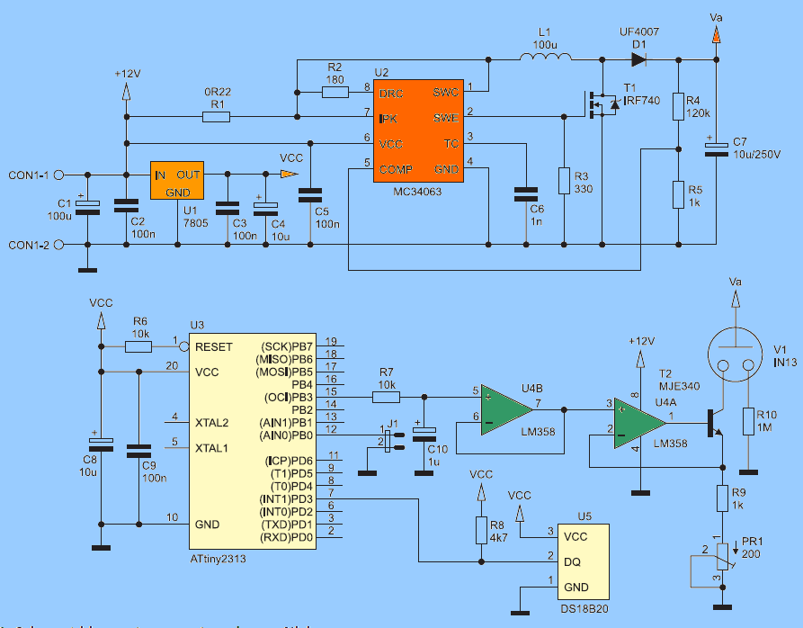
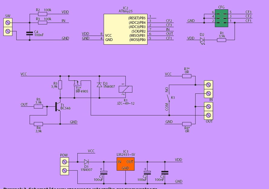
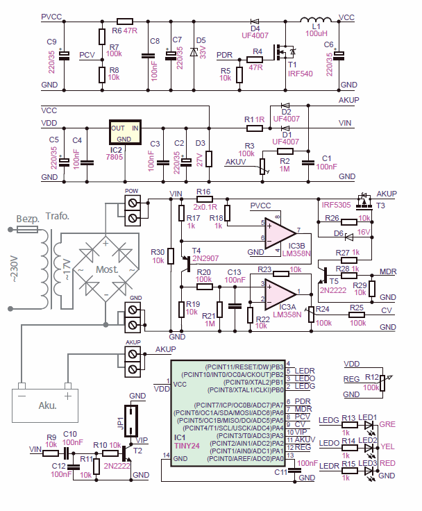
The Nixie thermometer schematic diagram is shown in Figure 1. The heart of the circuit is the ATtiny2313 microcontroller running on an internal RC oscillator with a frequency of 1 MHz. As a temperature sensor, the popular DS18B20 chip is used to measure from -55 to 125 ° C with a maximum resolution of 12 bits. The U1, together with the set of external components, stabilizes the 5 V voltage used to power the digital part of the thermometer

Due to the high flash voltage of the lamp, the MC34063 voltage suppressor inverter was used. The MOSFET T1 transistor, along with the gate-stop resistor R3, acts as a key. During conduction of the transistor the L1 choke stores the energy in the form of a magnetic field, and the diode D1 is polarized by blocking the C7 capacitor before discharging.

Source: NIXIE TUBE THERMOMETER CIRCUIT


Digital Soil Moisture Meter

$
0
0

A digital soil moisture meter is used for indicating the water content of a given soil sample. As crop production requires water at different stages and in different amounts, it is important to measure soil moisture from time to time to know its status.

Digital Soil Moisture Meter

The digital soil moisture meter circuit presented here, for monitoring the soil moisture content in irrigation farms, is an electronic device that measures soil moisture content accurately and precisely. It measures the resistance of flow of the electric current between two metallic probes. These probes act as sensor elements that register moisture and change it into an electric value. This value is further processed into information in the form of an electronic display.

Digital soil moisture meter circuit

Digital soil moisture meter circuit

Front-end of the digital soil moisture meter is a simple soil moisture sensor head, built around a few easily-available parts. Working of the sensor head electronics is self-explanatory, so just follow the conceptual drawing (and schematic drawing) shown in Fig. 1 to proceed with its construction.

Meter

PCB pattern of the soil moisture meter

Complete circuit diagram of the soil moisture meter is shown in Fig. 2. After construction of the sensor head, power it off a regulated 5V DC supply.

Component layout of the PCB

Insert the probes of the sensor head into the soil to determine its moisture content, and carefully adjust the preset VR1 so that voltage just above 3V is available at pin A1 of Arduino (Board1) if the soil is wet enough.

Construction and testing

Repeat the calibration process with randomly-collected soil samples ranging from very dry to very wet, depicting different moisture levels. Re-tune VR1, if necessary, until you are satisfied with the calibration process. (Note that the depths of penetration of the probes into the soil affect calibration.) Link the sensor head to the rest of the hardware to complete the project.
Rest of the hardware is a combination of Arduino microcontroller and a solid-state display panel. For compactness, Arduino Nano V3 platform is used to drive the 16×2 LCD panel.

Though a 6V battery pack is used to energise the hardware setup, you can also use external  DC power in 7V – 12V range at VIN of Board1 without any problem. The 10-kilo-ohm preset (VR2) is included to adjust the contrast level of the display. Similarly, the 100-ohm resistor (R2) limits the operating current of the backlight lamp inside the display panel.

For more detail: Digital Soil Moisture Meter

Ultrasonic Radar Model Using Microcontroller ATmega128

$
0
0

The circuit described here demonstrates the working of a radar system. It uses ultrasonic waves to detect an object and measure its distance and angular position, and displays the same on a 20×4 LCD screen. — Ashutosh M. Bhatt is an M. Tech in embedded systems (gold medalist). Currently, he is lecturer in electronics and radio engineering at Government Polytechnic, Jamnagar, Gujarat. He has been working on embedded systems since the last ten years

C4A Parts

Radar systems have a number of defence as well as civil applications. Air traffic control uses radars to track aircrafts on the ground and in the air, and to guide planes for smooth landings. Police use radars to detect the speed of passing vehicles. Geologists use radars to map the Earth and other planets. Military uses these for surveillance. Meteorologists use radars to track storms, hurricanes and tornadoes. The list is endless.

A radar system consists of a transmitter that transmits a beam towards the target, which is then reflected by the target as an echo signal. The reflected signal is received by a receiver. This receiver processes the received signal and provides such information as the presence of a target, distance, position (moving or stationary) or speed, which is displayed on a display unit.

Microcontroller based ultrasonic radar circuit

Actual radar systems are built with high-power transmitters and receivers, huge antennae, complex processing systems using digital signal processors and large displays.

This microcontroller based ultrasonic radar circuit demonstrates the working of a radar system. It uses ultrasonic waves to detect an object and measure its distance and angular position, and displays the same on a 20×4 LCD screen. It can detect multiple objects at different angles and distances as new objects are detected. This means that the distance and angle of all objects are displayed one by one on the same LCD screen.

The block diagram of an ultrasonic radar system is shown Fig. 1. The system includes an ultrasonic distance measurment (UDM) sensor, LCD panel, opto interrupt sensor, a motor driver, DC motor, buzzer and LEDs. The schematic of the system is shown in Fig. 2.

Block diagram of an ultrasonic radar system


ATMEGA48 TIMER TRIGGERED BY CURRENT FLOW ASM-010

$
0
0

ATMEGA48 Many devices may be in standby mode during downtime. They do not perform any work, they are apparently disabled, but the control circuits are powered. To extract useful information from the point of…Electronics Projects, ATMEGA48 Timer triggered by current flow ASM-010 “avr project, microcontroller projects, power electronic projects, “ATMEGA48 TIMER TRIGGERED BY CURRENT FLOW ASM-010

ATMEGA48 Many devices may be in standby mode during downtime. They do not perform any work, they are apparently disabled, but the control circuits are powered. To extract useful information from the point of view of working time, you should download it from the inside of the device, which may end up with a loss of warranty. ATMEGA48

If the sensitivity of the system is too low then the resistance R15 can be increased. Otherwise, if the current in the transformer flows high current, the transformer itself must be adjusted to avoid damage. Used in the prototype ASM-010 is adapted to a maximum of 10 A.

The LM358 is undoubtedly inexpensive, but its disadvantage is its relatively high unbalance voltage, which can, in very unfavorable conditions, mask the sinusoidal input signal. If the changes described above do not work, you may consider using another operating amplifier, eg TLC277. It is important that its input stage properly handles the voltage close to zero.

Once done, the counter system is ready to go. Current consumption is approximately 11 … 15 mA, depending on the current content of the LED display. The power supply should be a constant voltage, well filtered and not necessarily stabilized, in the range of 8 … 30 V.

At the moment of power failure the stabilizer stops supplying the divider and the output of the comparator is set. This rising edge causes the interrupt handler to operate in which the display is turned off, and the current time indication is stored in the EEPROM. This solution does not overwhelm the EEPROM with regular writing, which is justified because the number of write cycles written to it is limited.

ATMEGA48 ASM-010 SCHEMATIC DIAGRAM

ATMEGA48 ASM-010 SCHEMATIC DIAGRAM

The work time clock schematic diagram The microcontroller used here is ATmega48PA. In this application, its great advantage is the ability to operate at a supply voltage of 1.8 V. This is critical when writing data to non-volatile EEPROM when the system is powered exclusively from the filter capacity. The frequency of the microcontroller clock generator is stabilized with a quartz resonator (4 MHz). The same generator is used to measure time.

The display has 4 digits, each with a common anode. Control of all leads is done directly from the microcontroller terminals because the current of the segments is limited to about 2.5 mA, so that the whole digit does not take more than 20 mA.

Source: ATMEGA48 TIMER TRIGGERED BY CURRENT FLOW ASM-010

TINY USB PROGRAMMER AVR MICROCONTROLLERS AVRDUDE

$
0
0

USB programmer There are few components – the ATtiny45 microcontroller, two Zener diodes, a capacitor and several resistors. Of course, there are still connectors – USB plug and IDC-6 plug. Resistor R1 informs host… Electronics Projects, Tiny USB programmer AVR microcontrollers AVRDUDE “avr project, microcontroller projects, programmer circuit, “

TINY USB PROGRAMMER AVR MICROCONTROLLERS AVRDUDE

USB programmer There are few components – the ATtiny45 microcontroller, two Zener diodes, a capacitor and several resistors. Of course, there are still connectors – USB plug and IDC-6 plug. Resistor R1 informs host about presence of USB device transmitting data in Slow mode.

The resistors R2 and R3 in combination with D1 and D2 provide maximum voltages on the 3.6 V, not 5 V, because the +5 V voltage on the bus causes SYNC errors. R4 … R6 resistors protect the programmed circuit from damage if it is powered by a voltage lower than 5 V.

JP1 jumper should be open. It is assumed only when you want to power up the USB chip. Obviously, you need to keep in mind the limitations of the maximum permissible load current and the voltage range provided by the USB.

AVR USB PROGRAMMER SCHEMATIC DIAGRAM

AVR USB PROGRAMMER SCHEMATIC DIAGRAM

The whole programmer can be placed in a heat-shrink sleeve, but beforehand the microcontroller must be programmed. Microcontrollers provided in AVT sets are already programmed, but if you are building your own programmer, you have to do it yourself.

The microcontroller should be programmed in high-voltage mode because the zero line works like typical I / O. Such programmers have so called. parallel. However, you can do otherwise. Most programs do not allow the RST line to be disabled in SPI mode, but for example, AvrDude offers this capability. Using the Burn-OMat overlay, you can switch the RST line to I / O mode, only to enable Expert mode.

Configuring AVR Studio to work with USB tiny AVR Programmer:

From the “Tools” menu, select “Customize …”.
In the newly opened “Command” window, select the “Tools” tab.
We point to the “New” icon or press the “Insert” key.
We enter the name of the programmer, eg “USBtiny”.
In the “Command” window we indicate the path to “avrdude” (eg: C: WinAVR-20100110binavrdude.exe).
In the arguments window we specify the parameters: “-p m168 -c usbtinyp -P usb -U flash: w:” file. hex: a -U flash: v: “.hex file: a”, where “m168” is the type of processor.
In the “Initial directory”, enter the path to the file (note the final character “”)
We approve the changes with the “Close” button.

In order to program the microcontroller select the name of our programmer in the “Tools” menu (in this example it is “USBtiny”).

Configuring Bascom to work with USB tiny AVR Programmer:

From the menu select “Options / Programmer”.
Select “External programmer” from the drop-down list.
In the “Other” tab (at the bottom of the window) we give the path to “avrdude”.
In the parameter window, type “avrdude” -p m168 -c usbtiny -U flash: w: “{FILE}”: a -U flash: Where “m168” is the type of processor.

Programming with the F4 key or the “Program chip” icon.

SUPPORTED MICROCONTROLLERS AND THEIR CODES

ATmega128

m128

ATmega1280

m1280

ATmega1281

m1281

ATmega16

m16

ATmega162

m162

ATmega164

m164

ATmega168

m168

ATmega169

m169

ATmega2560

m2560

ATmega2561

m2561

ATmega32

m32

ATmega324

m324

ATmega328

m328

ATmega329

m329

ATmega3290

m3290

ATmega48

m48

ATmega64

m64

ATmega640

m640

ATmega644

m644

ATmega649

m649

ATmega6490

m6490

ATmega8

m8

ATmega8515

m8515

ATmega8535

m8535

ATmega88

m88

ATtiny12

t12

ATtiny13

t13

ATtiny15

t15

ATtiny2313

t2313

ATtiny25

t25

ATtiny26

t26

ATtiny45

t45

ATtiny85

t85

Source: TINY USB PROGRAMMER AVR MICROCONTROLLERS AVRDUDE

PROGRAMMABLE TIMER CIRCUIT ATTINY25

$
0
0

ATtiny25 Programmable Timer To describe the operation of the device, we will use an example – control of the electromagnetic bolt mounted in the wicket. In the simplest version we require that the push… Electronics Projects, Programmable Timer Circuit ATtiny25 “avr project, microcontroller projects, “PROGRAMMABLE TIMER CIRCUIT ATTINY25

ATtiny25 Programmable Timer To describe the operation of the device, we will use an example – control of the electromagnetic bolt mounted in the wicket. In the simplest version we require that the push button attaches the bolt electromagnet for a certain length of time, sufficient to reach the gate. Then, the solenoid should be turned off. When analyzing the situation more precisely, we find that the solenoid does not have to be turned on when it reaches the gate, and only when it reaches the gate. So we teach the device the following sequence: output disabled for 10 seconds, then turned on for 3 seconds, then temporarily off and end learning. From now on, after pressing the button, the device will perform exactly the same sequence that will trigger the lock after 10 seconds, once we reach the gate, stay drawn for 3 seconds and finally be released. ATtiny25

Diagrams showing action each mode and corresponding to it jumper setting

Diagrams showing action each mode and corresponding to it jumper setting

Programmable Timer Mode 1: Simple timer. As soon as the button is pressed, it starts playing the sequence until it is finished. During playback does not respond to the button.

Programmable Timer Mode 2: Interrupt timer. As in the first mode, but pressing the button during playback will immediately end the playback. As a result, the sequence can be aborted at any time by pressing the button again.

Programmable Timer Mode 3: Timer with restart. As in the first mode, but pressing the button during playback starts playing again.

Programmable Timer mode 4: End time switch. At the moment of pressing the button, it sets the first state of the sequence at the output and remains as long as the button is pressed. When the button is released, it starts playing the sequence, at that time it does not respond to the button.

Programmable Timer mode 5: Bistable switch. Each subsequent pressing of the button changes the state of the output to the opposite. The programmed sequence is not executed.

Programmable Timer 6: loop play. At the time when the button is pressed, a programmed loop sequence is output. Releasing the button immediately completes the sequence playback.

Programmable Timer 7: Sequence programming.

PROGRAMMABLE TIMER CIRCUIT ATTINY25

PROGRAMMABLE TIMER CIRCUIT SCHEMATIC ATTINY25

PROGRAMMABLE TIMER CIRCUIT SCHEMATIC ATTINY25

The schematic diagram Programmable Timer of the device is shown in Figure 2, and the assembly in Figure 3. The microcontroller application is straightforward and requires no discussion, just like assembly. All “power” of the programmable switch is included

Source: PROGRAMMABLE TIMER CIRCUIT ATTINY25

THERMOMETER HYGROMETER CIRCUIT USB DHT22 ATMEGA8

$
0
0

The presented layout is a snap on a computer for measuring DHT22 temperature and humidity. It measures the temperature from -40 to 80 ° C with a resolution of 0.1 ° C and accuracy… Electronics Projects,Thermometer Hygrometer Circuit USB DHT22 ATmega8 “atmega8 projects, avr project, microcontroller projects, “THERMOMETER HYGROMETER CIRCUIT USB DHT22 ATMEGA8

The presented layout is a snap on a computer for measuring DHT22 temperature and humidity. It measures the temperature from -40 to 80 ° C with a resolution of 0.1 ° C and accuracy of 0.2 ° C and humidity from 0 to 100% with a resolution of 0.1% and accuracy of 2%. The device was designed on a tiny size plate with the advantage of surface mount elements, so it can be used as a laptop or desktop adapter. The microcontroller control program was written in the Bascom AVR environment. The DHT22 sensortemperature and humidity reading

DHT22 THERMOMETER HYGROMETER CIRCUIT SCHEMATIC

DHT22 THERMOMETER HYGROMETER CIRCUIT SCHEMATIC

The schematic diagram of the thermometer Its “heart” is the ATmega8 microcontroller operating with an external 7.3728 MHz quartz resonator. The clock frequency was chosen so that the transmission error of the UART system was 0%.

The project uses the ATmega8 microcontroller in the smd TQFP32 housing and the FT232 chip in the SSOP28 enclosure, which, due to the raster patches, needs to be mounted on the rack. After soldering the microcontroller and the FT232 system, solder all jumper and serial components in order from smallest to largest.

Source: THERMOMETER HYGROMETER CIRCUIT USB DHT22 ATMEGA8

230V FAN REGULATOR CIRCUIT MOSFET MC33152 ATTINY25

$
0
0

Brushless asynchronous motors, with compact rotor windings, called short cages, are used to drive different fans. Their advantages are durability and simple construction. The presented layout uses a certain characteristic of such a fan… Electronics Projects, 230V Fan Regulator Circuit Mosfet MC33152 ATtiny25 “avr project, microcontroller projects, power electronic projects, “230V FAN REGULATOR CIRCUIT MOSFET MC33152 ATTINY25

Brushless asynchronous motors, with compact rotor windings, called short cages, are used to drive different fans. Their advantages are durability and simple construction. The presented layout uses a certain characteristic of such a fan to regulate its rotational speed.

The operation is based on a group control method – the motor is powered by a sinusoidal 230V AC for several full periods, and then the power is cut off for several more periods.

Turn on and off times range from a fraction of a second to a few seconds, and thanks to the inertia of the fan, there is no stopping and starting effect of the engine, only the effect of light “swing” rotation.

Switching time is constant while changing the pause time between successive starts is controlled by the output power supplied to the receiver and, consequently, the engine speed.

230V FAN REGULATOR SCHEMATIC

230V FAN REGULATOR SCHEMATIC

The ATtiny25 fan regulator’s schematic diagram is shown in Figure 2. The triacs “do not like” the inductive loads, so the rarely used circuit with the rectifier bridge and the P4NK60 MOSFET transistor are used instead of the triac actuator. This solution is more reliable in this application. The MC33152 special driver is correct for switching the transistor

The transformer, the LED and the IC3 stabilizer provide +5 V to power the ATtiny25 microcontroller. The diode signals the operation of the system – the flashing frequency is proportional to the set power, and the diode D5 and the resistors R5 and R4 form a zero-voltage detection system.

Source: 230V FAN REGULATOR CIRCUIT MOSFET MC33152 ATTINY25


1A 10A ADJUSTABLE BATTERY CHARGING CIRCUIT 100AH

$
0
0

Atmel ATTINY24 microcontroller based automatic battery charger circuit can charge 12V batteries with different power on (1A…10A current setting range of the charging current with limitation 10Ah, 20Ah, 30Ah, 40Ah, 50Ah, 60Ah, 70Ah, 80Ah,… Electronics Projects, 1A 10A Adjustable Battery Charging Circuit 100Ah “avr project, battery charger circuit, microcontroller projects, power electronic projects, “1A 10A ADJUSTABLE BATTERY CHARGING CIRCUIT 100AH

Atmel ATTINY24 microcontroller based automatic battery charger circuit can charge 12V batteries with different power on (1A…10A current setting range of the charging current with limitation 10Ah, 20Ah, 30Ah, 40Ah, 50Ah, 60Ah, 70Ah, 80Ah, 90Ah, and Max. 100ah wind with a capacity of 12V lead-acid batteries can be used. Current control 2x 0.1-Ohm 5w resistors with op-amp lm358 stone made through the power transistor as mosfet IRF 5305 is used because the lower heat LED indicator battery charging a dead Battery the simple charge from the section health status, etc. the information is being shown

Toroidal type transformer that is used in the battery charging circuit, the transformer output power 200W Atmel attiny24 microcontroller can be used on normal hair 17v charging circuit is performed with the source codes for different projects done with the project given Atmel ATTINY24 C Eagle PCB CAD drawings in addition to prosperity can provide includes

100ah wind the battery charging circuit in the box of Eagle PCB Eagle CAD drawing CAD drawings are used in the info panel with crafted with the schema of drawings, as well as beautiful designs we have seen panel that can be made in…

BATTERY CHARGER CIRCUIT DIAGRAM

BATTERY CHARGER CIRCUIT DIAGRAM

CHARGING CIRCUIT 100AH BOXED

CHARGING CIRCUIT 100AH BOXED


source: sklep.avt.pl/avt3120.html alternative link: 1a-10a-adjustable-battery-charging-circuit-100ah.raralternative link2

240W ELECTRONIC BALLAST CIRCUIT IR2104 ATMEGA48 CONTROLLED

$
0
0

IR2104 240W Fluorescent tube Ballast Circuit. Work was designed an electronic ballast for starting six fluorescent lamps with a total output of 240W with integrated dimming-controlled analog input and button. Priority is set to… Electronics Projects, 240W Electronic Ballast Circuit IR2104 ATmega48 Controlled“avr project, microcontroller projects, power electronic projects, “

240W ELECTRONIC BALLAST CIRCUIT IR2104 ATMEGA48 CONTROLLED

IR2104 240W Fluorescent tube Ballast Circuit. Work was designed an electronic ballast for starting six fluorescent lamps with a total output of 240W with integrated dimming-controlled analog input and button. Priority is set to control voltage. If the input voltage less than 0.5 V, tests with the push of a button. Measuring the voltage at the input is constant, and when voltage detection is higher than 0.5 V, occurs to the start of the fluorescent lamps and the subsequent setting of the intensity of the brightness-dependentthe inlet voltage, while when 5 V is set to the maximum intensity. When the control voltage it was necessary to introduce hysteresis due to the constant changing frequency. This hysteresis has been set step ±50 Hz. The resolution of the transfer of voltage to frequency is therefore in the set range of 80 steps.

ELECTRONIC FLUORESCENT BALAST CIRCUIT SCHEMATIC

ELECTRONIC FLUORESCENT BALAST CIRCUIT SCHEMATIC

Button can change the intensity of the brightness smoothly from the maximum after the minimum and back. In short pressing leads to switching on/switching off fluorescent lamps. When the measurement has been adjusted value of the inductor, 1.6 mH and ignition/operating frequency was set to 48 kHz. At this value the voltage at the fluorescent lamp was 104 In. The maximum frequency when the fluorescent lamp still shone was 62 kHz. The wiring is designed with a microcontroller ATmega48 and an integrated circuit of the IR2104240W ELECTRONIC BALLAST CIRCUIT IR2104 ATMEGA48 CONTROLLED

For sorting of fluorescent lamps has been chosen parallel arrangement mainly due to the power options directly from the mains 230 V/50Hz without the need to use increasing source of tension. Another advantage of this involvement is also the choice of the number of tubes from 1 pc to 6 pcs. The control program is written so that you can simply change the frequency stored in the variable zhav, light, max, and min. All the necessary calculations for the oscillator and the AD converter are contained in the program code and for the calculation of the required frequencies, the capacitor and inductors can be use conveniently program Ballast Designer V4 from the company International Rectifier.

starting light tube dimming lights tube preheat current ignition voltage

Source: 240W ELECTRONIC BALLAST CIRCUIT IR2104 ATMEGA48 CONTROLLED

IR2104 Ballast Circuit pcb schematic ATmega48 source code all files alternative links: 240w-electronic-ballast-circuit-ir2104-atmega48-controlled.rar alternative link2

0-30V 0-3A ADJUSTABLE SWITCHING LABORATORY POWER SUPPLY

$
0
0

DC-DC Laboratory Power Supply 0-30V 0-3A LT1074 is a switching regulator type step-down (lowering) with a maximum current of 5 A. Can work with the value of the input voltage up to 60 V… Electronics Projects,0-30V 0-3A Adjustable Switching Laboratory Power Supply “avr project, dc dc converter circuit, microcontroller projects, power electronic projects, power supply circuit, power supply project, “

0-30V 0-3A ADJUSTABLE SWITCHING LABORATORY POWER SUPPLY

DC-DC Laboratory Power Supply 0-30V 0-3A LT1074 is a switching regulator type step-down (lowering) with a maximum current of 5 A. Can work with the value of the input voltage up to 60 V version (HV) and the output voltage can be set in the range of 2.5 V – 50 In. Without modifying the circuit works the circuit with a frequency of 100 kHz.

LABORATORY POWER SUPPLY CIRCUIT SCHEMATIC

LABORATORY POWER SUPPLY CIRCUIT SCHEMATIC

The stabilized power supply with a controllable output voltage 0 – 30 V and a controllable current limitation 0 – 3 And. The source combines the use of the transformer, the switching regulator and the subsequent application of a linear regulator for better output characteristics. Implemented is also a measurement of the output voltage and current of the microcontroller, atmega644.0-30v 0-3a stabilized power supply dcdc

LT6105 The use of this circuit replaces the need to scan the current on the sensing resistor of the normal value (often 1 Ω), on which arises a large voltage drop and thus a large power loss including an increase in the internal resistance of the source. When using this circuit is the current sensed by the differential amplifier to the precision resistor of small value (for example, 0.01 Ω), which can be connected in any branch of the sources. Since this resistance value is small, there arises in him even a small power loss (given by the product of the resistance and the squared current). LT6105

dcdc lt1074 atmega644 laboratory power supply 30v lt6105

Source: 0-30V 0-3A ADJUSTABLE SWITCHING LABORATORY POWER SUPPLY

0-30v switchmode lab power supply circuit pcb schematic all files alternative links: 0-30v-0-3a-adjustable-switching-laboratory-power-supply.rar alternative link2

DIGITAL CLASS D AMPLIFIER CIRCUIT TAS5706A PCM1850A ATMEGA128

$
0
0

TAS5706A Class D Amplifier was itself the signal processor. From this parts depend all the other elements. Has an impact on the type of power supply, the control method of the type converter. That… Electronics Projects, Digital Class D Amplifier Circuit TAS5706A PCM1850A ATmega128 “audio amplifier circuits, avr project, class d amplifier circuit, ic amplifier, microcontroller projects, “

DIGITAL CLASS D AMPLIFIER CIRCUIT TAS5706A PCM1850A ATMEGA128

TAS5706A Class D Amplifier was itself the signal processor. From this parts depend all the other elements. Has an impact on the type of power supply, the control method of the type converter. That is why he was first selected DSP processor.

There are more firms that produce the processed signal processors whose internal connection is possible in many ways to reconfigure. However, the need was that the management was as simple as possible, therefore, programmable signal processors are discarded from consideration. Was selected processor TAS5706A from the company Texas Instruments. TAS5706A is a digital signal processor with fixed elements*1 and integrated by the final degree class D.

TAS5706A CLASS D AMPLIFIER CIRCUIT SCHEMATICS

TAS5706A CLASS D AMPLIFIER CIRCUIT SCHEMATICSTAS5706A CLASS D AMPLIFIER CIRCUIT SCHEMATICS FIG 2TAS5706A CLASS D AMPLIFIER CIRCUIT SCHEMATICS FIG 3

The digital audio signal is received from A/D into the DSP via four wires. SDIN (serial data in) is input navzorkovaných data. MCLK (master clock) is input signal has the highest frequency. SCLK (serial clock) is the input additional hour

PCM1850A from the company Texas Instruments. The converter was set into a fashion master, has the task to create hourly signal, and send the data separately. He was elected the format of left-justified with sampled by frequency of 48 kHz and a resolution of 24 bit. From the catalog letter [4] was to see that it is fully compatible with TAS5706A.DIGITAL CLASS D AMPLIFIER CIRCUIT TAS5706A PCM1850A

PCM1850A contains: 6 stereo inputs multiplexovaných, up to 24 bit resolution at the sampling frequencies of (16-96) kHz, Delta-Sigma A/D converter, anti aliasing filter, option mode the master or the slave, left-justified, I2S and right-justified output format, 256x, 384x, or 512x resampling, the output decimačný filter 64x upscaling.

ATmega128A is an 8-bit RISC mikrokontrolér with 128 kB memory for program FLASH, 4 kBram, SRAM and 4 kB memory EEPROM. Contains 8 and 16 bit counter, timers along with the generators PWM. The hardware-implemented blocks to support communication via the SPI and I2C. The computational performance on the taktovacej a frequency of 16 MHz up to 16 MIPS.

circuit tas5706a amplifier pulse width modulation pwm pcm1850atas5706a audio amplifier circuitstas5706a class d pcb

Source: DIGITAL CLASS D AMPLIFIER CIRCUIT TAS5706A PCM1850A ATMEGA128

tas5706a class d amp circuit pcb schematic all files alternative links: digital-class-d-amplifier-circuit-tas5706a-pcm1850a-atmega128.rar alternative link2

DIGITAL CLASS D AMPLIFIER PROJECT TAS5613 TDA9859 ATMEGA128

$
0
0

TDA9859 The main part of the preamplifier is an integrated circuit TDA9859, this integrated circuit is controlled via the I2C microprocessor Atmega128. Individual settings of the preamplifier through the keyboard are displayed on the… Electronics Projects, Digital Class D Amplifier Project TAS5613 TDA9859 ATmega128 “audio amplifier circuits, avr project, class d amplifier circuit, ic amplifier, microcontroller projects, “DIGITAL CLASS D AMPLIFIER PROJECT TAS5613 TDA9859 ATMEGA128

TDA9859 The main part of the preamplifier is an integrated circuit TDA9859, this integrated circuit is controlled via the I2C microprocessor Atmega128. Individual settings of the preamplifier through the keyboard are displayed on the graphical LCD display. Integrated circuit TDA9859 The preamp allows you to adjust the volume level, bass, treble, and balance in a wide range, allows you to switch between three stereo inputs, six mono inputs. The preamp also has the addition to the main stereo output also, one line output, which do not affect the setpoint correction, but only the selection of one entry. The individual parameters. The manufacturer is Philips.atmega128 class d circuit control

CLAS D CONTROL ATMEGA128

Microcontroller ATmega128 A very important circuit in the entire wiring pre-amplifier is a microcontroller, which is used to control the preamplifier TDA9859, control LCD displays, data processing And a/D converter, and scanning the keyboard. The market is available a large number of microcontrollers differing between each other by the width of registers and the bus, the number of input / output ports, the number of support circuits, and also the size of program and data memory.

Among the largest manufacturer of microcontrollers partying company of ATMEL, MICROCHIP, FREESCALE, etc. because Of experience with microcontrollers of ATMEL was elected 8-bit microcontroller ATmega128 from a number of ATmega, is based on the concept of Hardwardské architecture. Processor type RISC (Reduced Instruction Set Computer), thus has reduced the number of instructions. The instructions are executed in a single clock cycle. The big advantage is the possibility of a serial programming the microcontroller directly in the application, without the need for inserting it into the programmer. On the website of the manufacturer ATMEL’s freely available development environment AVR Studio 4.CLAS D CONTROL ATMEGA128

AUDIO CLASS D AMPLIFIER TAS5613

Output end of the class d amplifier was according to the needs of sound system elected to 100 W per channel, as the most suitable end amplifier was elected the integrated circuit TAS5613 company Texas Instruments, this is the circuit type “power stage”. The circuit has 4 separate channels, the speakers here are involved in the full bridge.

Integrated circuit TAS5613A is a high performance analog amplifier class-D with integrated technology with closed-loop feedback (known as PurePath HD technology). The amplifier is able to achieve output power up to 150 W (stereo) and 300W (mono) when using the speakers on the burden of 4 Ohms with a single supply voltage of 36 In. PurePath HD technology enables you to achieve performance comparable with the class AB and total harmonic distortion less how to 0,03 %. At the same time provides the energy efficiency of traditional amplifiers class D. PurePath HD technology enables to reduce losses during idle, so the device is more efficient.

tas5613 class d circuit schematictda9859 circuit schematic

Source: DIGITAL CLASS D AMPLIFIER PROJECT TAS5613 TDA9859 ATMEGA128

digital class-d amp circuit pcb schematic all files alternative links: digital-class-d-amplifier-project-tas5613-tda9859-atmega128.rar alternative link2

MULTI-FUNCTION DIGITAL WRISTWATCH CIRCUIT ATMEL ATMEGA168PA

$
0
0

Digital clock project PCB design is very good and prepared and used according to the coffers of small metal wristwatch. Except for a few digital Wristwatch circuit material including all the elements of SMD…Electronics Projects, Multi-function Digital Wristwatch Circuit Atmel ATmega168PA “avr project, microcontroller projects, “

atmel-atmega168pa-cok-fonksiyonlu-dijital-kol-saati

Digital clock project PCB design is very good and prepared and used according to the coffers of small metal wristwatch. Except for a few digital Wristwatch circuit material including all the elements of SMD type ATmega168PA digital clock project ski asm, eeprom, hex, etc. all code with source PCB layout drawing and the sprint, proteus isis simulation file

atmega168pa-dijital-kol-saati-dijital-saat-devresi

Digital Wristwatch circuit features

Clock – calendar:-hours, minutes, seconds, day, date, month, year, day of the week for the date can be displayed, Calculation, automatic summer and winter time (can be changed), takes into account leap years

2. two independent alarms (triggered melody is heard)

3.1-second increments the Scheduler. (Maximum duration 99h 59 m 59s)

4. Timer with two channels that have a resolution of 0.01 sec account. (Maximum operating time 99h 59 m 59s)

5. Account 1sn resolution with a stopwatch. (Maximum duration of use up to 99 days)

6. in the range of-5 ° C to 55 ° C Thermometer (temperature range is limited to the normal situation) with step 0.1 ° C

7. Reader and emulator hardware keys – tablet Dallas DS1990 through type with the ability to display the key code Bytes 1-Wire (I already have a few universal “off-road” memory 50 pieces).

8. Nikon Digital cameras “Pentax”, “”, “Canon” for the infrared rays remote control (only applied to “capture” command)

9. LED flashlight

10.7 ringtones

11. alarm clock (can be changed)

12. check the Voicemail button press (active)

13. the battery Voltage monitoring with Calibration function

14. Digital brightness control indicator

Read More Information…..

MULTI-FUNCTION DIGITAL WRISTWATCH CIRCUIT ATMEL ATMEGA168PA

ATMEGA8 USB EMAIL NOTIFIER CIRCUIT

$
0
0

Market “USB Mail Notifier” ready devices are sold, but in practice, ileginç project also ATmega8 microcontroller and the email account that connects the program’s source code (C + + RAD studiox) or not different… Electronics Projects, ATmega8 USB Email Notifier Circuit “atmega8 projects, avr project, microcontroller projects, “

 usb-ile-eposta-bildirimi-atmega8-usb-mail-notifier
Market “USB Mail Notifier” ready devices are sold, but in practice, ileginç project also ATmega8microcontroller and the email account that connects the program’s source code (C + + RAD studiox) or not different projects, mail server and microcontroller communication and so on. would be useful in developing for quite disabled to get the highest yield requirement to prepare an elegant box as in the picture 🙂 author box from the CD sleeve prepared to take the output from laser printers have used the mail icon
usb-mail-notifier
USB Mail Notifier Author: Bonio Often need to quickly respond to the email message came. Can be several times a day to check mail manually, in which case your interlocutor risk wait a whole day before you answer. You can use the special software which will check mail at a given interval of time and if there are new messages to report on it from the tray. But here it may be that you miss a message, for example, watching movies, or if you are at this moment not at the computer. To always know if there is new mail was invented USB Mail Notifier. The device is a USB plug on the box in an envelope, with a touch button on top. The front side of the “envelope” starts flashing continuously set the color, if you have new messages. Color is set from the control program. You can set any of the possible two, and mix them together. Touch button, you can run any program, such as email-client, or disable it altogether. USB Mail Notifier is a HID USB device, so drivers are not necessary.
usb-mail-notifier-cd-kutu
atmega8-usb-mail-notifier
use of computer software in addition to the email you are entering information when it comes to email blazing brightness of the LEDs can be adjusted as additional pressure sensor located on the circuit you want you can make a program work
Read More Information….

ATMEL ATTINY45 BLUETOOTH SCOREBOARD CIRCUIT

$
0
0

The scoreboard circuit is based on Atmel microcontroller ATtiny45 circuit cell phone can be controlled via bluetooth, the bluetooth module used in the indicator circuit BTM400-6B is an LCD TV has VGA output of…Electronics Projects, Atmel ATtiny45 Bluetooth Scoreboard Circuit “avr project, microcontroller projects, “

bluetooth-skorbord-atmel-attiny45-btm400-6b

The scoreboard circuit is based on Atmel microcontroller ATtiny45 circuit cell phone can be controlled via bluetooth, the bluetooth module used in the indicator circuit BTM400-6B is an LCD TV has VGA output of the circuit for the project and Android Bluetooth communication codes Scoreboard attiny45 eagle pcb, there is a very useful resource schema diagrams

Note: the library does not have schema attiny13 attiny45 used eagle looks microcontroller attiny45

Bluetooth Scoreboard This project aims to display a scoreboard in a regular VGA monitor, remotely controlled with an Android device (cellphone, tablet) via Bluetooth. Bluetooth module BTM400-6B will wait for a connection from a device (e.g. an Android phone) and will act as an Serial Port Profile re-passing everything received from the device to the UART interface. In our case the ATtiny will read the data but won’t “speak back” to the module, so it’s really a one way communication from that point of view. pretty simple: control a ping-pong electronic scoreboard from an Android bluetooth-enabled device. To do this, I used an ATtiny45 which main function is to display the current scores in a VGA monitor while reading from a bluetooth module UART interface waiting for “commands” that will tell it what to display. The Android device sends the commands via bluetooth, running an application specially designed for this project. As usual, the whole project is open source, including schematics, AVR firmware and the Android application.

electronic-scoreboard-btm400-6b-android-bluetooth-scoreboard-circuit

bluetooth-skorbord-atmel-attiny45-btm400-6b

scoreboard-vga-monitor-20mhz-attiny-atmelexternal-oscillator

Read More Information…

ATMEL ATTINY45 BLUETOOTH SCOREBOARD CIRCUIT

BATTERY ALARM CIRCUIT FOR MODEL HELICOPTERS ATTINY13

$
0
0

ATTINY13 Atmel microcontroller installed on the circuit model helicopter is checking the voltage of the battery the battery (or battery) voltage circuit when the level set LEDs, buzzer, giving the alam. ATTINY13 PB2, PB1,… Electronics Projects, Battery Alarm Circuit for Model Helicopters ATtiny13 “avr project, microcontroller projects, simple circuit projects, “

model-helikopter-icin-aku-alarm-devresi-attiny13

ATTINY13 Atmel microcontroller installed on the circuit model helicopter is checking the voltage of the battery the battery (or battery) voltage circuit when the level set LEDs, buzzer, giving the alam. ATTINY13 PB2, PB1, and PB0 pin chassis yaplılarak short circuit between the alarm can be set at a certain voltage circuit has very little material, if prepared pcb printed circuit board with SMD components becomes much smaller.

BATTERY ALARM FOR MODEL HELICOPTERS

In the model aircraft enjoy lithium polymer batteries (abbreviated Li-Po) very popular, but they, unlike their counterparts in mobile phones, cameras or portable media players, no built-in protection circuit. What this means for the user that he must be vigilant in seeing that the sensitive battery during charging and discharging is not damaged.

When you load one need most to worry, there are good chargers specifically for model or the model is the same for a suitable charger. Somewhat more problematic is the discharge – here, you naturally want to take advantage of the battery capacity as possible, on the other hand, should not the battery voltage falls below the permissible limit of 3.0 V per cell. Some models indicate these critical flight condition with an LED, but this is not always recognized in time. For this reason I developed the following circuit. This monitors the battery voltage in the flight model and shows by intense flashes of high brightness LEDs in time, the impending discharge of the battery. It can still be landed safely and the battery is protected against deep discharge.

battery-alarm-protection-circuit-model-helicopters

protection-circuit-battery-protected-deep-discharge-model-helicopters

Read More Information…

BATTERY ALARM CIRCUIT FOR MODEL HELICOPTERS ATTINY13

WINAMP REMOTE CIRCUIT BLUETOOTH AT90USB1287 NOKIA LCD LMX9838

$
0
0

A very detailed report of a project is already included in the schema, the author of the thesis, the eagle pcb source code etc. everything. The circuit used the main parts AT90USB1287 LMX9838 (Bluetooth… Electronics Projects, Winamp Remote Circuit Bluetooth AT90USB1287 Nokia LCD LMX9838 “avr project, microcontroller projects, “

 at90usb1287-lmx9838-bluetooth-winamp-kumanda-nokia-lcd

A very detailed report of a project is already included in the schema, the author of the thesis, the eagle pcb source code etc. everything. The circuit used the main parts AT90USB1287 LMX9838 (Bluetooth module) W681310 (PCM codec IC) Indicator is being used in hardware resources, as well as the Nokia LCD for C/C++ codes with the Winamp Plugin and other program files are also useful for different projects.

avr-at90usb1287-lmx9838-bluetooth-w681310-pcm-codec

WINAMP~1

The goal of this project is to create a complete and functional product, starting from scratch. Thus, you will see in this report many steps described, starting from the choice of components to the
creation of DLLs for Windows. We want to create a Bluetooth remote control having several functionalities:

– Display on a small LCD screen the tracks in the multimedia player’s them using the keys on the

– Display on the LCD the currently played track and its playing status

– Headset functionality: it is possible to plug a standard remote in order to use the remote control as a headset to make

– External keyboard capability: when the remote control is appropriate USB cable, the remote will be detected as an external keyboard (using the HID class). Thus, if the user’s computer doesn’t have a Bluetooth chip, he will still be control his multimedia player using the special keys

– Provide a platform with free tools: the compiler and the development environment are free, the compiled program can be sent to the microcontroller by using the USB bootloader. Thus anyone can develop on the remote without spending money

– Good autonomy: the remote control will be powered using a lithium battery which will be
charged when the remote Thus, the only part of the whole system on which this project relies is the Windows Bluetooth system drivers, since we don’t take care of the low level parts of the Bluetooth communication. This project uses the serial port profile on top of the Bluetooth stack playlist; remote. status. microphone and headphones on the VoIP calls connected to a computer using on the remote. rm on the development tools. is connected to a computer, using USB power.

AT90USB1287: 8Mhz, 128kb flash memory, embedded USB bootloader, free compiler (WinAVR)
LMX9838: Bluetooth to UART converter with embedded antenna, Serial Port Profile
Winbond W681310: cheap audio codec supported by the LMX9838
Nokia Color LCD: cheap 130*130 pixels screen interfaced using SPI bus

Read More Information…

WINAMP REMOTE CIRCUIT BLUETOOTH AT90USB1287 NOKIA LCD LMX9838

PORTABLE RF JAMMER CIRCUIT ATMEGA48

$
0
0

So far I have ever seen , tidy and with all the resources shared jammer circuit project design, it’s very smart Sizes also pretty small pocket on the internet a lot jammer circuit ,… Electronics Projects, Portable RF Jammer Circuit ATmega48 “avr project, microcontroller projects, “

 atmega48-tasinabilir-rf-jammer

So far I have ever seen , tidy and with all the resources shared jammer circuit project design, it’s very smart Sizes also pretty small pocket on the internet a lot jammer circuit , however, this circuit more like simple but integrates most of us in our market does … Circuit of the printed circuit board 3 floor consists of output power in the 1watt high band , low band 3watt

Jammer circuit mobile phone battery with 3.7v supply provided with integrated voltage converter dcdc used in raising the necessary parts . Jammer on the ATMEGA48 microcontroller , ROS2500 , ROS1200 , SXE- 389, LM358 , etc. ad8402 . abundance outside the integrated voltage regulator and converter used dcdc

CAUTION Jammer frequency to a frequency of the same value , is a device to signal that suppresses the original signal . jammer is forbidden to use this project to share the purpose of source code and PCB drawings is that the different projects, the PLLs , high frequency for operations such as C code may work influenced, may also RF PCBs in designing resource eagle pcb design would be helpful

self-tuning-portable-rf-jammer-dual-pll-therefore

jammer-circuit-pll-rf-jammer

Source: ladyada.net/make/wavebubble/index.html alternative link: portable-rf-jammer-circuit-atmega48.raralternative link2 alternative link3 alternative link4

Read More Information….

PORTABLE RF JAMMER CIRCUIT ATMEGA48

ATMEGA32 PCB DRILL MACHINE

$
0
0

This document describes the construction of a PCB drill machine driven by a master-controller board and three stepper motor driver boards. These four single sided PC boards each contain an Atmega16/32 microcontroller. Communication between… Electronics Projects, ATMEGA32 PCB drill machine “avr project, microcontroller projects, “

atmega32-pcb-drill-machine

This document describes the construction of a PCB drill machine driven by a master-controller board and three stepper motor driver boards. These four single sided PC boards each contain an Atmega16/32 microcontroller. Communication between the boards is performed using the RS485 protocol with all communication initiated by the master-controller. The Atmega16/32 software is completely written in Bascom-AVR.

On the master-board a PS2-connector to connect a PS2-keyboard. Furthermore a 8 x 24 LCD. A RJ45-connector for the RS485-bus. A Max232 for serial communication. An Atmega32 is controlling all.

PCB-DR~1

On the stepper motor driver board an Atmega16. A RJ45-connector for RS485-communication. A fan to keep the temperature of the drivers for the stepper motor at a reasonable level. A stepper motor driver-board is an autonomic device. It gets a command from the master-controller-board and it takes care of the stepper motor motion, error-detection and error-correction. The initiative of communication on the RS485 bus is at the master-controller-board. It submits the stepper motor commands and will wait until the commands are done.

RS485-connection. The initiative for communication is always done by the master-board. It sends the commands to the slaves and waits till the slave comes back with a READY or ERROR-message. Depending on the ERROR-code a resend of the command is done (slave sends an error-message because the checksum is not right), slave sends a READY when the command is finished.

For the design of printed circuit boards we have chosen Eagle. With Eagle’s CAM-processor an Excellon drill-file is generated. This Excellon file is presented to the Drill-machine and the Drill-machine will do his drilling from top to bottom of the file. We haven’t made any tool change equipment, but by running the Excellon file several times from top to bottom, we can use different drills. To monitor the RS485-communication-bus we added a small piece of electronics.

And now, with a communication program, like HyperTerminal, we can monitor all traffic on the RS485-communication-bus.

PCB-drill-machine

PCB drill machine

PCB-drill-machine-avr-pcb

PCB drill machine electronic projects files: atmega32-pcb-drill-machine.RAR alternative link2 alternative link3

Read more information….

ATMEGA32 PCB DRILL MACHINE

Viewing all 1082 articles
Browse latest View live