Quantcast
Channel: AVR ATmega Projects Archives - Projects Tutorials Code Library for Atmels Atmega32 AVR
Viewing all 1082 articles
Browse latest View live

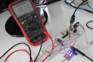
UV Sensor ML8511 AVR Atmega library

$
0
0

Ultraviolet (UV) is an electromagnetic radiation with a wavelength from 10 nm to 400 nm.
The ML8511 is an ultraviolet sensor that output an analog signal correlated to the amount of UV light detected. By datasheet the sensor detects wavelength from 280nm to 560nm.

UV Sensor ML8511 AVR Atmega library

Here I’ve implemented a driver for AVR Atmega, portable to other microcontrollers, that correlates the sensor output to light intensity, it also computes the UV index based on the sensor input.
The ultraviolet index or UV index is an international standard measurement of the strength of sunburn-producing ultraviolet (UV) radiation at a particular place and time. It is a linear scale, with higher values representing a greater risk of sunburn. The purpose of the UV Index is to help people effectively protect themselves from UV radiation.
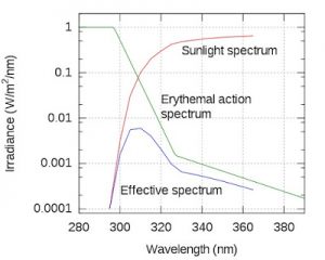
Not all the energy of the UV spectrum has the same “damage” power, due to this the power spectrum is multiplied by a weighting curve known as the erythemal action spectrum, and the result integrated over the whole spectrum.
The correlation function I propose here is derived by the datasheet graph of “Output Voltage over UV intensity“.

From this graph we can get the correlation function. This graph is clearly a linear function. We have Output voltage on the y axis and UV intensity on the x axis.
Because we want to obtain the UV intensity using the voltage that we can read from the sensor, we are going to flip the graph.

Once we have flipped the graph we can now get the point from the graph using a tool like WebPlotDigitizer.
We can now use liner regression technique to obtain the function we need to convert voltage output to UV intensity.
Also notice that this graph has four functions for 75degree, 25degree, -5degree, -25degree temperature condition.
If we perform linear regression on points of that function we get 4 correlation functions.
@75deg UV mW/cm2 = 8.158154634V -7.77772054
@25deg UV mW/cm2 = 7.9816914V-7.921745308
@-5deg UV mW/cm2 = 7.853758854V – 7.934095316
@-25deg UV mW/cm2 = 7.743732684V – 7.978602568
Note thate the accuracy of this method depends on the accuracy of your point extraction.
More in general we can say that the correlation function looks like this:

UV Sensor ML8511 AVR Atmega library schematics

If we are going to use this sensor under different thermal condition we can simply interpolate beween those function to get the correlation function slope “s” and intercept “i”.
Also, that graph is for a wavelength of 365nm.
We may find the responsivity function of this sensor on the datasheet. Responsivity measures the input–output gain of a detector system. We can use again the WebPlotDigitizer to find points from the “Responsivity Characteristics” curve.

Read more: UV Sensor ML8511 AVR Atmega library 


Interfacing GSM Module with AVR Microcontroller: Send and Receive Messages

$
0
0

GSM modules are interesting to use especially when our project requires remote access. These modules could make all actions that our normal mobile phone could do, like making/receiving a call, sending/receiving a SMS, connecting to internet using GPRS etc. You can also connect a normal microphone and speaker to this module and converse on your mobile calls. This will open doors to lot of creative projects if it could be interfaced with a Microcontroller. Hence in this tutorial we will learn how we can Interface the GSM module (SIM900A) with AVR microcontroller ATmega16 and will demonstrate it by sending and receiving messages using GSM Module.

Interfacing GSM Module with AVR Microcontroller Send and Receive Messages

Materials Required

  1. Atmega16
  2. GSM module (SIM900 or any other)
  3. LCD display
  4. Push buttons
  5. 10k resistors, Potentiometer
  6. Connecting wires
  7. 12V Adapter
  8. USBasp programmer
  9. 10 pin FRC cable

Software Used

We will use CodeVisionAVR software for writing our code and SinaProg software for uploading our code to Atmega16 using USBASP programmer.

You can download these softwares from the given links:

CodeVisionAVR : http://www.hpinfotech.ro/cvavr_download.html

SinaProg : http://www.ablab.in/sinaprog-hex-file-downloader-software-to-download-code-to-avr-microcontroller/#inline_content

Before going into the schematics and codes, we learn about GSM module and its working.

GSM Module

The GSM module can be used even without any microcontroller by using the AT command mode. As shown above the GSM module comes with a USART adapter which can be directly interfaced to the computer by using a MAX232 module or the Tx and Rx pins can be used to connect it to a Microcontroller. You can also notice the other pins like MIC+, MIC-, SP+, SP- etc where a microphone or a Speaker can be connected. The module can be powered by a 12V adapter through a normal DC barrel jack.

Insert your SIM card in the slot of the module and power it on, you should notice a power LED going ON. Now wait for a minute or so, and you should see a red (or any other colour) LED Flashing once for every 3 seconds. This means that your Module was capable to establish connection with your SIM card. Now you can proceed with connecting you module with Phone or any Microcontroller.

You can build many cool projects using GSM module like:

Also check all the GSM related projects here.

Communicating with GSM module using AT commands

As you might have guessed it, the GSM module can communicate through Serial communication and could understand only one language and that is “AT commands”. Whatever that you might want to tell or ask to the GSM module it should only be via AT commands. For example if you want to know if your module is active. You should ask (send) a command like “AT” and your module will reply “OK”.

Interfacing GSM Module with AVR Microcontroller Send and Receive Messages schematics

These AT commands are well explained in its data sheet and can be found here in its official datasheet. Okay! Okay! It is a 271 page datasheet and you might take days to read through them. So I have given some most important AT commands below for you to get this up and running soon.

AT

Replies with OK for Acknowledgement

AT+CPIN?

Check signal Quality

AT+COPS?

Find service provider name

ATD96XXXXXXXX;

Call to the specific number, ends with semi-colon

AT+CNUM

Find the number of SIM card (might not work for some SIM)

ATA

Answer the Incoming Call

ATH

Hang off the current Incoming call

AT+COLP

Show incoming call number

AT+VTS=(number)

Send DTMF number. You can use any number on your mobile keypad for (number)

AT+CMGR

AT+CMGR=1 reads message at first position

AT+CMGD=1

Delete message at first position

AT+CMGDA=”DEL ALL”

Delete All messages from SIM

AT+CMGL=”ALL”

Read all messaged from SIM

AT+CMGF=1

Set SMS configuration. “1” is for text only mode

AT+CMGS = “+91 968837XXXX”

>CircuitDigest Text<Ctrl+z>

Sends SMS to a particular number here 968837XXXX. When you see “>” start entering the text. Press Ctrl+Z to send the text.

AT+CGATT?

To check for internet connection on SIM card

AT+CIPSHUT

To close TCP connection, meaning to disconnect form internet

AT+CSTT = “APN”,”username”,”Pass”

Connect to GPRS with your APN and Pass key. Can be obtained from Network Provider.

AT+CIICR

Check if SIM card has data pack

AT+CIFSR

Get IP of the SIM network

AT+CIPSTART = “TCP”,”SERVER IP”,”PORT”

Used to set a TCP IP connection

AT+CIPSEND

This command is used to send data to server

Here we will use AT+CMGF and AT+CMGS command to send messages.

If you have used GSM module with Arduino, while receiving messages you can use +CMT: command to view the mobile number and text message on serial monitor. Text message comes on second line as shown in picture.

Read more:

Interfacing RF module with Atmega8: Communication between two AVR Microcontrollers

$
0
0

Making our projects Wireless always makes it to look cool and also extends the range in which it can be controlled. Starting from using a normal IR LED for short distance wireless control till an ESP8266 for worldwide HTTP control, there are lots of ways to control something wirelessly. In this project we learn how to build wireless projects using a 433 MHz RF module and AVR microcontroller.

Interfacing RF module with Atmega8 Communication between two AVR Microcontrollers

In this project we do following things:-

  1. We use Atmega8 for the RF Transmitter and Atmega8 for the RF Receiver section.
  2. We interface an LED and a Pushbutton with Atmega8 microcontrollers.
  3. On the transmitter side, we Interface Pushbutton with Atmega and transmit the data. On the receiver side, we will receive the data wirelessly and show the output on LED.
  4. We use encoder and decoder IC to transmit 4 bit data.
  5. Reception Frequency is 433Mhz using cheap RF TX-RX module available in the market.

Components Required

  1. Atmega8 AVR Microcontroller (2)
  2. USBASP programmer
  3. 10-pin FRC cable
  4. Bread board (2)
  5. LEDs (2)
  6. Pushbutton (1)
  7. HT12D and HT12E pair
  8. RX-TX RF Module
  9. Resistors (10k,47k,1M)
  10. Jumper Wires
  11. 5V power supply

Software Used

We use CodeVisionAVR software for writing our code and SinaProg software for uploading our code to Atmega8 using USBASP programmer.

You can download these softwares from the given links:

CodeVisionAVR http://www.hpinfotech.ro/cvavr_download.html

SinaProg : http://www.ablab.in/sinaprog-hex-file-downloader-software-to-download-code-to-avr-microcontroller/#inline_content

Before going into the schematics and codes, let’s understand the working of RF module with Encoder-Decoder ICs.

433MHz RF Transmitter and Receiver Module

Those are the transmitter and receiver modules we are using in the project. It is the cheapest module available for 433 MHz These modules accepts serial data in one channel.

If we see the specifications of the modules, the transmitter is rated for 3.5-12V operation as input voltage and the transmit distance is 20-200 meters. It does transmit in AM (Audio Modulation) protocol at 433 MHz frequency. We can transfer data at a speed of 4KB/S with 10mW power.

In the upper image we can see the pin-out of the Transmitter module. From the left to right the pins are VCC, DATA and GND.  We can also add the antenna and solder it on the point denoted in the above image.

For the Receiver specification, the Receiver has a rating of 5V dc and 4MA Quiescent current as input. The receiving frequency is 433.92 MHz with a -105DB sensitivity.

In the above image we can see the pin-out of the receiver module. The four pins are from Left to right, VCC, DATA, DATA and GND. Those middle two pins are internally connected. We can use any one or both. But it is a good practice to use both for lowering the noise coupling.

Also, one thing is not mentioned in the datasheet, the variable inductor or POT at the middle of the module is used for frequency calibration. If we couldn’t receive the transmitted data, there are possibilities that the transmitting and receiving frequencies are not matched. This is a RF circuit and we need to tune the transmitter at the perfect transmitted frequency point.  Also, same as the transmitter, this module also has an Antenna port; we can solder wire in coiled form for longer reception.

The transmission range is dependable on the voltage supplied to the Transmitter and the length of the antennas in both side. For this specific project we did not used external antenna and used 5V at the transmitter side. We checked with 5 meters distance and it worked perfectly.

Interfacing RF module with Atmega8 Communication between two AVR Microcontrollers schematics

Learn more about RF pair in the RF Transmitter and Receiver Circuit. You can understand more about the working of RF by checking following projects that uses RF pair:

Read more: Interfacing RF module with Atmega8: Communication between two AVR Microcontrollers

Interfacing HC-05 Bluetooth module with AVR Microcontroller

$
0
0

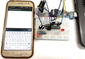
In this tutorial let us learn How to interface HC-05 Bluetooth Module with AVR ATmega8 microcontroller. We will establish communication between Android mobile and Atmega8 through Bluetooth module which takes place through UART serial communication protocol. In this project we will control a LED using Bluetooth of our smartphone.

Interfacing HC-05 Bluetooth module with AVR Microcontroller

Material Required:

  1. AVR Atmega8
  2. HC-05 Bluetooth module
  3. LED
  4. USBASP programmer
  5. 10-pin FRC cable
  6. Jumper wires
  7. Breadboard

Software Used:

We will use CodeVisionAVR software for writing our code and SinaProg software for uploading our code to Atmega8 using USBASP programmer.

You can download these softwares from the given links:

CodeVisionAVR : http://www.hpinfotech.ro/cvavr_download.html

SinaProg : http://www.ablab.in/sinaprog-hex-file-downloader-software-to-download-code-to-avr-microcontroller/#inline_content

Bluetooth Module HC-06:

Bluetooth can operate in the following two modes:

  1. Command Mode
  2. Operating Mode

In Command Mode we will be able to configure the Bluetooth properties like the name of the Bluetooth signal, its password, the operating baud rate etc. The Operating Mode is the one in which we will be able to send and receive data between the PIC Microcontroller and the Bluetooth module. Hence in this tutorial we will be toying only with the Operating Mode. The Command mode will be left to the default settings. The Device name will be HC-05 (I am using HC-06) and the password will be 0000 or 1234 and most importantly the default baud rate for all Bluetooth modules will be 9600.

The module works on 5V supply and the signal pins operate on 3.3V, hence a 3.3V regulator is present in the module itself. Hence we need not worry about it. Out of the six pins only four will be used in the Operating mode. The pin connection table is shown below

S.No

Pin on HC-05/HC-06

Pin name on MCU

Pin number in PIC

1

Vcc

Vdd

31st pin

2

Vcc

Gnd

32nd pin

3

Tx

RC6/Tx/CK

25th pin

4

Rx

RC7/Rx/DT

26th pin

5

State

NC

NC

6

EN (Enable)

NC

NC

Check our other projects to learn more about Bluetooth module HC-05 with other microcontrollers:

Creating the Project for Atmega 8 using CodeVision:

After installing these softwares follow the below steps to create project and writing code:

Step 1. Open CodeVision Click on File -> New -> Project. Confirmation Dialogue box will appear. Click On Yes

Step 2.  CodeWizard will open. Click on first option i.e. AT90, and click OK.

Step 3. Choose your microcontroller chip, here we will take Atmega8 as shown.

Step 4. Click on Ports. In our project, we will be using Port C4 and C5 for led interfacing. So, make Bit 4 and bit 5 as output by clicking on it. As shown below:

Step 5. We will use USART for Rx and Tx. So, click on USART option and click on Receiver option and leave rest as it is.

Step 6. Click on Program -> Generate, Save and Exit. Now, more than half of our work is completed

Step 7. Make a New folder on desktop so, that our files remains in folder otherwise it we will be scattered on whole desktop window. Name your folder as you want and I suggest use the same name to save program files.

Interfacing HC-05 Bluetooth module with AVR Microcontroller schematics

We will be having three dialogues box one after other to save files.

Do the same with other two dialogue boxes which will appear after you save the first.

Now, your workspace looking like this.

Our most of the work is completed with the help of the Wizard. Now, we have to write only few lines of code to interface the bluetooth module and control the LED.

Read more: Interfacing HC-05 Bluetooth module with AVR Microcontroller

Make Your Own WiCard WiFi Module on a Breadboard

$
0
0

Like Arduino you can make your own WiCard on a breadboard. All you need are resistors, capacitors, breadboard, wires, ATmega8, and ESP8266.

Make Your Own WiCard WiFi Module on a Breadboard

Story

ATmega16 Analog-Looking Digital Clock Project

$
0
0

Atmega16 microcontroller in our circuit monitor 7 inch in size. Screen “3 inch” or “4 inch” may be, it doesn’t matter. We have the biggest screen by controlling the foot links we could find…. Electronics Projects, ATmega16 Analog-Looking Digital Clock Project “avr project, microcontroller projects, ”

ATmega16 Analog-Looking Digital Clock Project

Atmega16 microcontroller in our circuit monitor 7 inch in size. Screen “3 inch” or “4 inch” may be, it doesn’t matter. We have the biggest screen by controlling the foot links we could find.

In circuit 7805 voltage regulated chip. 9 Volt battery restraints when it integrated provides the proper functioning of the circuit elements, constants and 5 volts.

Proteus isis circuit diagram;

Proteus isis circuit diagram

Integration of the DS1307 circuit for clock function. This is the chip clock frequency 32.768 KHz crystal. DS1307 internal structure, integrated circuit a typical Foot connection shapes and hours link shape respectively the following illustration.

Integration of the DS1307 circuit for clock function.

Integrated circuit time signal from 5 and 6 hours. 3-volt CR2032 battery 3 end-to-end networked to that memory clock is not lost. Pull up resistors and two standing no. 5 and 6 as well as the processor 27-28 and 29 of the restraints the buttons. This is in keeping with the arrival of the signal logic status 1 pinlerdeki resistors beautiful preventing parasites.

Our processor is the Atmega is 16. We may also use the Atmega 32 this is not much different. Only capacity differs. Foot links are the same.

LCD screen located on the touchpad cable wear and use anywhere.

LCD screen located on the touchpad cable wear and use anywhere

ATmega16 Analog-looking digital clock for the project proteus isis schema, pcb and code files: ATmega16 Analog-Looking Digital Clock Project.rar

Alternative File Download LINK list (in TXT format): LINKS-22771.zip

MultiPurpose Atmel Development Boards Project

$
0
0

Atmel series microcontrollers series to prepare for the software quality testing to ensure ease in your test circuit has 3 different test circuit. ATmega8, ATMega16, atmega162, ATtiny2313 and ATTINY13 made ​​to the circuit RS232… Electronics Projects, MultiPurpose Atmel Development Boards Project “avr development board, ”

MultiPurpose Atmel Development Boards Project

Atmel series microcontrollers series to prepare for the software quality testing to ensure ease in your test circuit has 3 different test circuit.

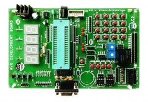
ATmega8, ATMega16, atmega162, ATtiny2313 and ATTINY13 made ​​to the circuit RS232 to RS485 keyboard LEDs LCDs and a lot more input and output sections DS18X20 sensors midi input dip-switches EEPROM triac floors have whatever you a super design moreover pcb drawing is on.

Atmel AVR Development Boards

Atmel AVR Development Boards

Only atmel atmega162 programming feature of the test circuit which has the jumper settings and 2 × 8 and 16 × 2 LCD display with LED bar display indication and button can be connected there. SDA and SCL I2C EEPROM at24cxxx. 16 pin connector for external connections RS232 serial port swic’s bottom.

 LED bar display indication and button can be connected there

At89cx051 and have the same characteristics for the ATTINY2313 devresinde the test section is in addition to the IR receiver.

At89cx051 and have the same characteristics for the ATTINY2313 devresinde

Source: mirley.firlej.org All development, test circuit for atmel alternative link: multipurpose-atmel-development-boards-project.rar alternative link2 alternative link3

Alternative File Download LINK list (in TXT format): LINKS-8950.zip

Keypad Door Lock using AVR Microcontroller – Atmega16

$
0
0
  • Password Based Keypad Door Lock

 In this article, a digitally secured lock based on password verification is explained. The system uses a seven segment display array to show the password, a matrix keypad to enter the numbers/password and operates a relay (to activate the solenoid valve) for locking and unlocking purpose. The system alarms through a buzzer if a wrong password is entered for 3 times continuously and an SMS is sent to a predefined contact number. The password can be changed whenever required, but only after correctly entering the present password. The password is stored in the EEPROM of the microcontroller so that, power failure or reset of the system does not affect the password recognition.

Keypad Door Lock using AVR Microcontroller – Atmega16

Circuit Diagram

 The system contains a seven segment display array, a 4X4 matrix keypad and a GSM module to send the status message. Based on these requirements, any microcontroller with 3 I/O ports and one UART peripheral is sufficient. In this article ATMEGA16 microcontroller is used. The circuit is developed using the Proteus Simulation software to demonstrate the operation. There is a real-time feature called the ‘Virtual Terminal’ in this software which is used in this article to send the SMS through a GSM Module connected to the computer.

The circuit diagram for connecting the GSM module to the computer is shown below. A detailed explanation on this procedure is provided in the article, “Virtual Comports in Proteus”.

The Matrix Keypad

 In this circuit, a 4X4 matrix keypad is used to enter the password and to interact with the system. A function called the ‘get_key’ function is used to read the pressed key and this key information is passed to the ‘run_key_function’ which is a ‘switch statement’ with 16 cases, and is assigned with one case for each key. As there are 16 keys in the keypad, key value ranges from 1 to 16 and by default, the key value is set out of this range during initialization of the key variable. The ‘get_key’ function refreshes the columns and reads the rows for detecting the pressed key (if any). Whenever a key is pressed this default value is replaced by the currently pressed key. Now, the ‘run_key_function’ is executed and corresponding statements for the pressed key are executed. After execution of these statements, the display function is called until the pressed key is not released. Soon after the key is released, again the key value is set out of range. Below is the program code for the functions ‘get_key’. The ‘get_key’ function can be easily modified for keypads other than the 4X4 matrix.

Keypad Door Lock using AVR Microcontroller – Atmega16 schematics

The Display

 As the password is of four digits, four seven segment LED’s are multiplexed. There is an option to show/hide the password while entering. The display function presented in this article uses one for loop and it can be modified easily if the number of digits is varied. If the show option=1 then digits are shown as they are and if show option=0 then the ‘G’ segment of the displays is enabled instead of the entire digit. The program code for the display function is shown below.

Read more: Keypad Door Lock using AVR Microcontroller – Atmega16


Bluetooth Home Automation using AVR and Android App

$
0
0

DIY-Bluetooth based Home Automation Project

In this project, let’s see how to design a Bluetooth based home automation project.This article explains the steps involved in the designing of a Bluetooth home automation kit, starting from the configuration of a Bluetooth module. The article also explains how to select an App, read the keywords sent by the App and how to develop a microcontroller program compatible with the selected App. Program file and Program code are provided, which can be readily used. By the end of the article, a complete ready to use Home automation kit is developed.

Bluetooth Home Automation using AVR and Android App

Program file (hex file) and Program code are provided, which can be readily used after downloading. Finishing this tutorial, you should be able to design and develop a complete bluetooth based home automation kit.

Selection of the Android App:

Android Apps are readily available in Play Store for home automation using Bluetooth module. We have to select an App that suits our requirement. The number of loads or appliances that are controlled by the app is the basic criteria for app selection. This number should match with the actual number of relays/loads in our Automation Hardware kit. In this article, we are using an 8-Channel Relay board i.e., it can control 8 Loads or devices (like fan, light etc). So, we need to select an App that can control 8 Loads.

One of the Apps that are available in the Play store is presented here.

Download Android App – for Bluetooth Control

Keywords from the Android App:

The reader will be able to develop the microcontroller program for any App by knowing the commands used by the App to control devices. The Android App sends specific characters to ON/OFF a particular load. These characters can be single alphabets, numbers, special characters or words. This is decided by the App Designer/Programmer. These specific characters are referred as Keywords in this article.

The App developer may or may not provide the Keywords in the description of the App. In order to use the App, it is essential to know these Keywords. One of the simple methods to find the keywords is presented here.

Bluetooth Home Automation using AVR and Android App schematics

The idea is to interface the module with the hyper terminal software using a USB-Serial converter. The procedure below explains how to use the hyper terminal software and send the commands using the USB-Serial converter. Please read our article on Interfacing Bluetooth modules for a detailed explanation.

Read more: Bluetooth Home Automation using AVR and Android App

Interfacing LCD Module with AVR in 4-Bit Mode

$
0
0

This article is another step forward in learning more about AVR microcontrollers. We have demonstrated interfacing of LCD module with ATmega328 microcontroller, which will help you to learn its basic concepts. ATmega328 is an eight bit AVR (Advanced Virtual RISC) based microcontroller. It is a powerful microcontroller with a built-in  internal memory of around 32Kb. Atmega 328 has only 28 pins.

Interfacing LCD Module with AVR in 4-Bit Mode

Therefore it have only limited number of  GPIO pins. While  designing complex projects we need sufficient number of I/O pins . An LCD module can be interfaced with a microcontroller either in 8 bit mode or in 4 bit mode.  8 bit mode is the conventional mode which uses 8 data lines and RS, R/W, E pins for functioning. However 4 bit mode uses only 4 data lines along with the control pins. This will saves the number of GPIO pins needed for other purpose.

Let’s begin to build our project!

Circuit Diagram

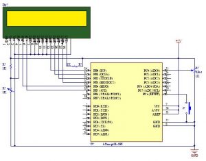
As shown in the circuit diagram, port B and port D of the controller is used for interfacing it with LCD module. In 4 bit mode only 4 lines D4-D7, along with RS, R/W and E pins are used. This will save us 4 pins of our controller which we can use it for other purpose. Here we only need to write to the LCD module. So the R/W pin can be ground it as shown in the schematic diagram.

In this way the total number of pins can be reduced to 6. In 4 Bit mode the data bytes are split into two four bits and are transferred in the form of a nibble. The data transmission to a LCD is performed by assigning logic states to the control pins RS and E. The reset circuit, oscillator circuit and power supply need to be provided for the proper working of the circuit.

Important Aspects of the Program

Download Program

The programming part is done in embedded C using Atmel studio 7 .At the beginning of the program a pre-processor named “F_CPU” is defined. It is simply your way to tell some of the library code how many CPU cycles per second the processor is executing. Here we defined the F_CPU as 16 MHz. “#include <avr/io.h>” is a header files which provides you with various  i/o operations like DDRx, PINx, PORTx, etc. “#include <util/delay.h>” is a header file which provides you with inbuilt delay functions like _delay_ms(), _delay_us(), etc. “_delay_ms(1000)” provides a delay of 1000 milliseconds (i.e., equivalent to 1 second).

DDRx – Data Direction Register configures data direction of the port(Input/Output). The instruction “

PORTx – Port register is for assigning appropriate values for the port pins.

Writing to PORTx.n will immediately change state of the port pins according to given value.

The port and the corresponding pins that we used are defined at the beginning. According to your circuit, you can alter the port name and pin number in the program.

Interfacing LCD Module with AVR in 4-Bit Mode schematics

A subroutine called “ LCD_CmdWrite()” is used for sending commands to the LCD. In this function the 8 bit data is break into two 4 bit data and send to LCD as nibbles. The command register of the LCD is the selected by writing a ‘0’ to the RS pin. The writing operation is done by simply enabling the E pin of LCD for few microseconds. Similarly the subroutine called “ LCD_DataWrite()” is used for sending data to the LCD. The data register of the LCD is the selected by writing a ‘1’ to the RS pin.

Read more: Interfacing LCD Module with AVR in 4-Bit Mode

Simple LED Projects Using AVR Microcontroller

$
0
0

This article is another step forward in learning more about AVR microcontrollers. We have demonstrated 3 simple LED based projects using ATmega328 microcontroller, which will help you to learn its basic concepts. ATmega328 is an eight bit AVR (Advanced Virtual RISC) based microcontroller. It is a powerful microcontroller with a built-in  internal memory of around 32Kb. Most Arduino boards consist of an Atmel 8-bit AVR microcontroller with varying amounts of flash memory, pins, and features. Arduino Uno is a microcontroller board based on the ATmega328.

Simple LED Projects Using AVR Microcontroller

AVR microcontrollers are very easy to use. All AVR microcontrollers require Integrated Development Environment(IDE) such as Atmel Studio. Using this IDE, we can create, compile and debug program on all AVR microcontrollers.

Let’s develop simple LED Blinking programs for ATmega328 using Atmel Studio 7.

  1. Blinking Two LED’s using ATmega328
  2. Control Two LED’s using a Push button switch
  3. Toggle Two LED’s using a Push button switch

#1. Blinking Two LED’s using ATmega328

 In this section, we will learn How to blink two LEDs with AVR ATmega328 microcontroller. First, we will connect the 2 LED’s with PB2 and PB3 of  PORTB of the ATmega328 microcontroller. Then, we will make the 2 LED’s to blink with an interval of 1 second. It means, initially the 1st LED alone will glow and on the next second, it will turn off and the 2nd  one will glow. This process continues forever and in this way LEDs blinks continuously.

Assemble the circuit as shown in diagram. A photograph of the assembled circuit is shown below. A video demonstration of the project is shown below.

Program Explanation

Blinking Two LED’s Using ATmega328 – Download Program

 At the beginning of the program a pre-processor named “F_CPU” is defined. It is simply your way to tell some of the library code how many CPU cycles per second the processor is executing. Here we defined the F_CPU as 1 MHz. “#include <avr/io.h>” is a header files which provides you with various  i/o operations like DDRx, PINx, PORTx, etc. “#include <util/delay.h>” is a header file which provides you with inbuilt delay functions like _delay_ms(), _delay_us(), etc. “_delay_ms(1000)” provides a delay of 1000 milliseconds (i.e., equivalent to 1 second).

DDRx – Data Direction Register configures data direction of the port(Input/Output). The instruction “ DDRB |= (1<<DDB2)”  makes corresponding port pin as output.

Simple LED Projects Using AVR Microcontroller schematics

PORTx – Port register is for assigning appropriate values for the port pins.

Writing to PORTx.n will immediately change state of the port pins according to given value. “PORTB |=(1<<PORTB2)” will generate a high signal at PB2. And “PORTB&=~(1<<PORTB3)” is for generating a low signal at PB3.

Read more: Simple LED Projects Using AVR Microcontroller

How to work with the ADC unit of an AVR Micro-controller

$
0
0

Introduction

The first step to digital signal processing is to convert a signal into digital data, and here the Analog to Digital Converter devices comes into action. Some of the AVR micro controllers include ADC unit in their features. This is a very useful unit for measurement related applications. The ADC used in AVR micro controllers are of successive approximation converter type. Read the Wikipedia article on SAR type ADC here. And you can read the Circuitstoday article too.

How to work with the ADC unit of an AVR Micro-controller

Using the ADC Unit

SAR type ADC needs these following things to run properly:

  • A very stable, low internal impedance, very low noise DC Supply
  • A Reference voltage
  • A clock signal for the digital circuitry

And few input signals necessary for the control of operation these are

  • ADEN, ADC Enable signal
  • ADSC, ADC Start Conversion
  • & Channel number to Multiplexer. This helps to select the ADC channel to perform a conversion operation.

Register Description & Minimum Configurations Required

ADC Multiplexer Selection Register – ADMUX

Bit

7

6

5

4

3

2

1

0

Bit Name

REFS1

REFS0

ADLAR

MUX3

MUX2

MUX1

MUX0

Read/Write

RW

RW

RW

R

RW

RW

RW

RW

Initial value

0

0

0

0

0

0

0

0

Bit 7:6 – REFS1:0: Reference Selection Bits

These bits select the voltage reference for the ADC, as shown in Table below. If these bits are changed during a conversion, the change will not go in effect until this conversion is complete (ADIF in ADCSRA is set). The internal voltage reference options may not be used if an external reference voltage is being applied to the AREF pin.

Interrupt Sense Control

REFS1

REFS0

Voltage Reference Selection

0

0

AREF, Internal VREF turned off

0

1

AVcc with External capacitor at AREF pin

1

0

Reserved

1

1

Internal 2.56V Voltage Reference with external capacitor at AREF pin

Bit 5 – ADLAR: ADC Left Adjust Result

Bits 3:0 – MUX3:0: Analog Channel Selection Bits

The value of these bits selects which analog inputs are connected to the ADC. See table below for details. If these bits are changed during a conversion, the change will not go in effect until this conversion is complete (ADIF in ADCSRA is set).

Input Channel Selections

MUX3

MUX2

MUX1

MUX0

Selected ADC Channel

0

0

0

0

ADC0

0

0

0

1

ADC1

0

0

1

0

ADC2

0

0

1

1

ADC3

0

1

0

0

ADC4

0

1

0

1

ADC5

0

1

1

0

ADC6 (Only for SMT Package)

0

1

1

1

ADC7 (Only for SMT Package)

1

0

0

0

1

0

0

1

1

0

1

0

1

0

1

1

1

1

0

0

1

1

0

1

1

1

1

0

1.30V (VBG)

1

1

1

1

0V (GND)

Bit 7 – ADEN: ADC Enable

Writing this bit to one enables the ADC. By writing it to zero, the ADC is turned off. Turning the ADC off while a conversion is in progress, will terminate this conversion.

How to work with the ADC unit of an AVR Micro-controller schematics

Bit 6 – ADSC: ADC Start Conversion

In Single Conversion mode, write this bit to one to start each conversion. This first conversion performs initialization of the ADC. ADSC will read as one as long as a conversion is in progress. When the conversion is complete, it returns to zero. Writing zero to this bit has no effect.

Read more: How to work with the ADC unit of an AVR Micro-controller

How to Work With 32K crystal and AVR Microcontroller

$
0
0

This article teaches you how to add 32K external crystal source to  AVR micro controller (Atmega8 ) with circuit diagram & C program.

Introduction

Timing-is one of the basic function, performed by the micro controllers. Every microcontroller has at least one timer/counter module in its architecture.  However if the counter is clocked internally a few issues may arise in some cases. Sometimes the clock frequency may not stable, or sometimes the clock frequency may be too high than necessary. Sometimes external clock is required to have the required quality. To solve these problems, some AVR micro controllers comes up with an inbuilt oscillator supporting 32.768KHz crystal. User just need to attach the tank circuit along with the 32K Crystal.

How to Work With 32K crystal and AVR Microcontroller

For a demonstration of this, we would try to blink an LED. We will use the output of the timer. Microcontroller used here is ATmega8. The component list is as below:

Component

Qty

ATmega8

1

LED

1

Resistor

1

Push Button switch

1

32768Hz Crystal

1

33pF Ceramic capacitor

2

Extra: Programmer, Bread board, 5V Power Supply

Now, we have one Input Capture register, and we can obtain an electrical output in the OC2 Pin (PORTB, Pin 3). And we must keep the following points in mind while programming:

  • Human Eye can sense any periodic activity with at least 100mS of period. TCNT2 Pre-scalar can scale down the clock frequency to ATMOST 1024th PART, Pulse Width Modulation (PWM) modes will divide the frequency to 256th part. This can give a period of AT MOST 8 Second (1024*256/32768). In this demonstration, we are pre-scaling the clock to 1024th Part.
  • We can use a NON Pulse width Modulation mode like CTC mode to blink the LED too. In this demo, we are using CTC mode.
  • The DDRXn bit (Data Direction Register ‘X’, Bit ‘n’) must be ‘1’, to which, the OC2 ( Output Compare of Timer/Counter 2) is connected. In case of ATmega8, it is pin no 17 of the IC. Corresponding Data Direction Register is DDRB, and pin no is 3.

So let us make circuit and Write the program.

Fig: Circuit Diagram

// Program written for ATmega8
#define F_CPU 1000000
#include
#include
#include

void initTimr()
{ ASSR =0x08; // ASSR enables clocking
// From 32kCrystal
TCNT2 =0x00;
OCR2 =32; // As this is a CTC mode
// value of OCR2 determines
// the period
TCCR2 =0b10011111; // TCCR2 Configured for CTC mode.
// Frequency pre-scaled to
// 1024th Part.
// OCR2 toggles in compare match
while((ASSR&0x07)); // Wait until updating of the
// Above 3 register completes
TIFR =0x00;
}

int main()
{ DDRB=0b00001000; // The DDRXn bit must be ‘1’
// corresponding to OCR2
_delay_ms(2000);
initTimr();
sleep_cpu(); // Halts The CPU. Here, you
// can use ‘while(1);’ too
return 0;
}

Read more: How to Work With 32K crystal and AVR Microcontroller

Frequency counter circuit

$
0
0

Simple Frequency Counter

You may have already seen various projects over many websites named Frequency counter, Digital Frequency Counter etc. I’m posting just another of them. Showing the use of timer/counter of AVR micro controller (Atmega8) in one of it’s form. This circuit can be used as a simple micro controller project for your engineering courses. Frequency of a periodic signal is the number of cycles it repeats per second!   So If we count the number of cycles recorded in a second it will directly read the frequency. So what we are going to make is a frequency counter circuit, which can also be called as a frequency meter.

Frequency counter circuit

To make this frequency meter 1) we need a signal (whose frequency has to be counted) 2) Atmega8 micro controller from Avr 3) An LCD to display the counted frequency. I assume that you are familiar with Avr Atmega8 and you know how to program it. You also need to know – How to interface LCD with Avr

Now let’s get into the details of the project – Simple Frequency Counter or otherwise Frequency Meter!

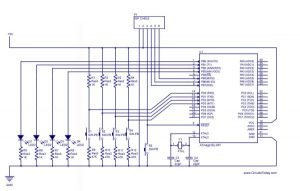
Take a look at the circuit diagram given below and also skim through the program given towards the end of this article.

Description of circuit:-

So what I have done here is; Set the counter to zero, waited for 1S, and read  the counter again. But remember,you need to read the value immediately after the delay loop ends. It is simple. Just assign a variable and copy the count to that. The data type of the variable is essentially an unsigned integer. You can try floating point data type too! But here you need to typecast it! That’s all!  To read about floating point conversion in Avr – read this article carefully – String Formatting of Avr

And yes! It’s better that you apply a conditioned signal for counting the frequency. i.e. a square wave or a trail of pulses. You may use a suitable signal conditioning circuit like Comparator;   Schmitt trigger, sine wave to square wave converter, whatever suits you. If the signal is of low power, then use a conditioning circuit . You can get lots of signal conditioning circuits in this website – check here – Signal Conditioner Circuits

Now here is the Technical details of my project. I hope you’ll have not much problem to make this.

The program [Embedded C, AVR Studio]:

#define F_CPU 1000000
#include
#define SMP 1

int main(void)
{ unsigned int i;
stdout=&lcd_str;
initLCD();

_delay_ms(50);

while(1)
{ TCNT1 =0;
_delay_ms(1000/SMP);
i=TCNT1;
LCDcmd(0x01);
printf(“Freq:%uHz”,i*SMP);
_delay_ms(500);
}
return 0;
}

Read more: Frequency counter circuit

Standard Library & String Formatting for AVR

$
0
0

Here in this article, I am planning to brief you through the Standard library of AVR-GCC. By the term “Standard Library” we mean the “Standard header” files like “stdio.h”, we commonly see in C programming language. Have you ever used String Formatting in ANSI C? Did you use Standard library functions? If you are familiar with C programming language, then you must be familiar with standard header files we write in the beginning of the program like “#include stdio.h“, “#include stdlib.h” , “#include conio.h” etc etc. The most important of all header files is the header file -which simply means “Standard Input Output header file”. It is by adding this header file, we make the compiler recognize and interpret standard library functions like “Scanf” (to get input) and “Printf” (to output to a device like display or pinter).

Standard Library & String Formatting for AVR

printf(“Hello! % d %f %c %s”,a,b,c,d);

Now I hope you have got some idea about what I’m going to tell. Before going deep into this article, I would like to show you some tutorials I have written before, which will be useful for you.

1. An Introduction to Atmega32

2. An Introduction to Atmega8

3.  Avr Studio Overview for Beginners

4. Avr Gcc Library – An Overview
Okay! Now I am going to show you an important difference between programming in C and for the Avr-Gcc.  In C programming, you just need to write the command printf(“Hello! % d %f %c %s”,a,b,c,d); to send these string of characters all together to the output device, like a display or a printer.The “printf()” function makes it easier for you. It takes care of the conversion portion.

In AVR studio there the end compiler is AVR-GCC framework. A header file named ‘stdio.h’ comes here too. The ‘printf()’ function prototype is defined there. But here it demands complete description of a routine to send a single character to the display device or a routine that will send a string of characters. The prototype of the routine must match with the return types and arguments as demanded by the end compiler. Else the function will malfunction or will not get compiled at all (resulting in error).

Standard Library & String Formatting for AVR schematics

Now the complete code of the “printf()” and its core functions are quite big. It involves string formatting including the floating point conversation. The implementation of integer conversion is much smaller. So AVR Studio offers three flavors of the ‘printf()’! One implements moderate functionality of the string formatting (signed integer conversion), another low (only unsigned integer conversion), and the last one offers full functionality of that (including signed and unsigned floating point and same of that integer conversion). To use full or lower functionality, you’d have to request the compiler to compile those specific implementations. Otherwise, the unimplemented formatting would place a ‘?’ character in the formatted string. To do this you’d have to modify some settings. You’ll find it in this article.

Read more: Standard Library & String Formatting for AVR


Handling the Digital Input Output in AVR Micro Controllers

$
0
0

I have already discussed about a few chapters necessary to get into AVR programming. Now this is the first article that deals with programming.  Let us start with the basics.

Handling the Digital Input Output in AVR Micro Controllers

Digital input output (I/O) is the basic feature supported by  AVR micro controller. To facilitate digital input output, three registers are associated with each port of the micro controller.

  • Data Direction Register– This register determines which of the pins will act as an output port, and which of them as input.
  • Data Output Register-This register holds the Data output to the port.
  • Data Input Register– Reads data from the port

Now let us look into an example. For Port A the three registers are- DDRA, PORTA & PINA respectively. Similarly for port B, it will be- DDRB, PORTB & PINB.

Now before going to further discussion, there is  one important thing I should mention. One port serves for more than one purpose. It is the designer’s responsibility to eliminate every possible error. If the program and system are not designed carefully, fallacy may appear.

Circuit Diagrams using Atmega32 and Atmega8

Note: Click on the circuit diagram to get a large and clear view.

And find below the circuit using Atmega8

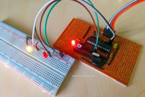
Glow an LED using Avr Microcontroller

Program 1: Basic Program Showing Digital Output functionality.

#include
#define F_CPU 1000000
#include
int main()

{ DDRB=0x0f;

PORTB=0x00;

while(1)

{ _delay_ms(1500);

PORTB =~PORTB;
}

return 0;
}

Description:

This program consists of two simple statements, including one delay loop. The ‘~’ symbol stands for bitwise not operation. Here CPU operating Frequency must be defined for proper implementation of the delay loop, and it has to be declared before the ‘delay.h’  line in the C code. Here I’ve used the #define F_CPU  1000000.

There is another option available to define the CPU Operating frequency. In Avr Studio, go to ‘Project Menu> Configuration Options> General’. Here you can choose your device model and its operating frequency.

As I’ve previously discussed, The Data direction register must be set up before doing any input/output operation.

Handling the Digital Input Output in AVR Micro Controllers schematics

Desired Output:

The LEDs connected to Port B blinks with 3 second time period.

Hex Files: 

Note: All the HEX files given in this article are converted to RAR format (for safety and size reduction purpose). To get the HEX file as such – you may download each  file and EXTRACT it to your computer using Winzip or Winrar.

Read more: Handling the Digital Input Output in AVR Micro Controllers

Avr Atmega8 Microcontroller – An Introduction

$
0
0

In my previous article, I’ve discussed about ATmega32. Now, let me introduce another member of AVR microcontroller family, the ATmega8. This member has many features similar to that of ATmega32. But it has reduced number of features and capabilities, yet it has enough features to work with. Now let me tell you that if you want to gather knowledge and at the same time want to do it in less cost than the budget of ATmega32, you can think of making projects with ATmega8. In that case, one feature you won’t be able to realize is the JTAG interface. But rest of the features are available in this IC. Let us see what one can get from ATmega8.

Avr Atmega8 Microcontroller – An Introduction

Here find the pin diagram of Atmega8 microcontroller:-

Memory: It has 8 Kb of Flash program memory (10,000 Write/Erase cycles durability), 512 Bytes of EEPROM (100,000 Write/Erase Cycles).  1Kbyte Internal SRAM

I/O Ports: 23 I/ line can be obtained from three ports; namely Port B, Port C and Port D.

Interrupts:  Two External Interrupt source, located at port D. 19 different interrupt vectors supporting 19 events generated by internal peripherals.

Timer/Counter: Three Internal Timers are available, two 8 bit, one 16 bit, offering various operating modes and supporting internal or external clocking.

SPI (Serial Peripheral interface): ATmega8 holds three communication devices integrated. One of them is Serial Peripheral Interface. Four pins are assigned to Atmega8 to implement this scheme of communication.

USART: One of the most powerful communication solutions is USART and ATmega8 supports both synchronous and asynchronous data transfer schemes. It has three pins assigned for that. In many projects, this module is extensively used for PC-Micro controller communication.

TWI (Two Wire Interface): Another communication device that is present in ATmega8 is Two Wire Interface. It allows designers to set up a commutation between two devices using just two wires along with a common ground connection, As the TWI output is made by means of open collector outputs, thus external pull up resistors are required to make the circuit.

Analog Comparator: A comparator module is integrated in the IC that provides comparison facility between two voltages connected to the two inputs of the Analog comparator via External pins attached to the micro controller.

Avr Atmega8 Microcontroller – An Introduction schematics

Analog to Digital Converter: Inbuilt analog to digital converter can convert an analog input signal into digital data of 10bit resolution. For most of the low end application, this much resolution is enough.

Read more: Avr Atmega8 Microcontroller – An Introduction

AUTOMATIC FEEDING MACHINE WITH CD-ROM MECHANIC

$
0
0

For the author, the automatic feeding machine for the wedge is the easiest mechanical part for the application. they insert a plastic container all of which is placed on the CD present on the… Electronics Projects, Automatic Feeding Machine With CD-ROM Mechanic “avr project, microcontroller projects, “

Automatic feeding machine with cd rom mechanic

For the author, the automatic feeding machine for the wedge is the easiest mechanical part for the application. they insert a plastic container all of which is placed on the CD present on the CD-ROM and put the ready-made cat here.

Attiny13 Automatic feeding circuit A simple driver circuit is used for engine control based on the Attiny13 microcontroller. The operating voltage of the feeding circuit is 9v Attiny13 supply 78L05 regulator provided with the project’s proteus simulation scheme, source codevision avr c, hex code files are available.

When the over voltage is applied, the D2 LED flashes. By pressing the button briefly, the sled opening time can be selected as 12, 24, 36, 48 hours. The time setting is indicated by led: 12 hours, 2 times 24, 3 times – 36, led light without pause. Pressing the button for a long time, if necessary, opens or closes the rails. This does not affect the Timing setting.

Timer ready modules are sold more easily to control the application. This circuit can be done by using CD-ROM mechanism with different circuit, devices and automatic feeding system.

AUTOMATIC FEEDING CIRCUIT SCHEMATIC

Schematic automatic feeding machine with cd rom mechanic

Circuit automatic feeding machine with cd rom mechanic

source: AUTOMATIC FEEDING MACHINE WITH CD-ROM MECHANIC

ATMEL ARDUINO COLORED CONNECTION CHART

$
0
0

Projects or schematics, drawings that will work when preparing pcb Atmel AVR Microprocessors Information Tags for “Share” drawings directly on Atmel microcontrollers. Colored linking expansions are more comprehensible for those dealing with Atmel Series… Electronics Projects, Atmel Arduino Colored Connection Chart “arduino projects, “

ATMEL ARDUINO COLORED CONNECTION CHART

Projects or schematics, drawings that will work when preparing pcb Atmel AVR Microprocessors Information Tags for “Share” drawings directly on Atmel microcontrollers.

Colored linking expansions are more comprehensible for those dealing with Atmel Series microcontrollers or Arduino projects It will be. Most of them are in high resolution .PDF version.

ATMEL ARDUINO SAMPLE LINK EXTENSIONS

ATMEL ARDUINO SAMPLE LINK EXTENSIONS

CIRCUIT ATMEL ARDUINO SAMPLE LINK EXTENSIONS

COLORED CONNECTION CHART LIST ARDUINO ATMEL

Arduino Adafruit Feather 32u4 Adalogger
Arduino Adafruit Feather 32u4 Bluefruit LE
Arduino Adafruit Feather 32u4 Basic Proto
Adafruit Feather 32u4 RFMxx
Adafruit Feather 32u4 Fona
Adafruit METRO
Arduino Mini
Arduino Pro Mini
Arduino Fishino GUPPY
Arduino Fishino GUPPY Mega
Arduino Fishino UNO
Arduino Lilypad USB
Arduino Lilypad SimpleSnap
Arduino Lilypad Simple
Arduino LilyPad
Arduino FioEthernet
Arduino Esplora
Arduino Micro
Arduino Mini
Arduino Nano
Arduino Pro
Arduino Pro Mini
Arduino Yun
Arduino Leonardo
Arduino Mega
Arduino 2009
Arduino Uno

Source: pighixxx.com/test/

ATMEGA8 FT232R USB ESR METER CIRCUIT

$
0
0

USB ESR Meter Circuit The main part of the meter is a ATmega8 microcontroller that controls the entire device. Its main the task is to process measured data and perform calculations so that the… Electronics Projects, ATmega8 FT232R USB ESR Meter Circuit “atmega8 projects, avr project, microcontroller projects, “

ATMEGA8 FT232R USB ESR METER CIRCUIT

USB ESR Meter Circuit The main part of the meter is a ATmega8 microcontroller that controls the entire device. Its main the task is to process measured data and perform calculations so that the result is real ESR value. This value is displayed on the LCD. Another task of the ATmega8 microcontroller is communication with a USB controller that then communicates with a computer, that is sends measured data and allows the meter to be controlled via the computer.

The requirements of the A / D converter in this particular application, ie the ESR meter, are not at all critical for the transfer time. There is no need for a high-speed converter, it will also be slower, which will also result in greater accuracy, which is for the application important (ESR meter does not need to measure ESR value many times per second, it is enough once per second, but accuracy is important). Another important parameter converter is a resolution. This depends on the desired measuring range of the meter. The advantage is using a multichannel converter, when it is possible to measure other than ESR quantities. A typical example is the measurement of the battery voltage, which can be used to monitor the rate of discharge.

SCHEMATIC ATMEGA8 FT232R USB ESR METER CIRCUIT

SCHEMATIC ATMEGA8 FT232R USB ESR METER CIRCUIT

FT232R Communication via USB has been selected for communicating the meter with the personal computer protocol. Simply because this interface is based on virtually everyone computers, unlike today’s extruded parallel or serial ports. The USB interface is also much more resistant to disturbances than the parallel port, for example to use as a 5 V supply.

For this reason, it was decided to use the FT232R circuit whose datasheet can be used found on. This is a USB protocol converter to a serial UART. On the side of the computer the circuit can communicate via the USB 2.0 version 2.0 speed to Full Speed, that is, up to 12 Mbit / s. The circuit communicates across the device (microcontroller) via serial protocol, that is, using the wires for receiving and transmitting serial data (RxD and TxD).

CIRCUIT ATMEGA8 FT232R USB ESR METER

For more detail: ATMEGA8 FT232R USB ESR METER CIRCUIT

Viewing all 1082 articles
Browse latest View live


Latest Images