Ring Tone Text Transfer Language (RTTTL) is a simple text-based code for recording monophonic musical tones. The script is usually loaded into a mobile phone, which is able to convert the code to equivalent musical notes. Many early phones had an integrated RTTTL player, which played these codes, serving as a ring tone.
Here is a neat little program I wrote for playing simple monophonic tunes on an ATMega32. This was the first program I wrote, to parse a string and it works really well. I figured it was better to make a RTTTL Player, as there are already many tunes available from the mobile phone industry. Originally, I wrote this for a PIC microcontroller and decided to port the code to the ATmega32. I was hoping to play “Rule Britannia”, but there are no RTTTL scripts for this currently. If you find one, please feel free to email it.
An advantage of this program is that it does not use timers or pulse width modulation (PWM), specific to any microcontroller IC architecture. This means that the code will work on almost any microcontroller. The program simply toggles the output of a pin, between 5 V and zero, very fast. The square wave generated drives the piezo speaker directly.
I have kept the program code as simple as I can by using “if-else-if”, and “do-while” loops, for parsing. There are other ways, but I want to keep it simple for students who are just starting out.
Postman Pat – Playback
postmanpat
Here is proof that the code actually works.
RTTTL Standard
The text based data string has not been standardised, and consequently many manufacturers have made slight changes to it. Sometimes a ring tone for one brand of mobile phone will not work for another brand. Sometimes the string may contain a duration value of 64, or 128. There are also variations in the octave scale as well. The program that I have created expects the following format.
“song title:d=duration, o=octave, b=beatpermin:[length][note][#][octave][period.],”
- Valid duration values are 1, 2, 4, 8, 16, and 32.
- Valid octaves are 4, 5, 6, and 7.
- Beats per minute can be a value between 1 and 3 digits long.
RTTTL Parameter Sequence
When the code parses the string, the following parameter values are expected.
- The standard values 1, 2, 4, 8, 16, and 32 are the duration lengths of a note.
- The notes are a, b, c, d, e, f, g, h, p, c#, d#. f#, and g#, where p is a silent pause or rest.
- The hash symbol # signifies a sharp note.
- The octave value provides the following scales 4, 5, 6, and 7.
- A period symbol denotes a pause length multiplier of 1.5.
Octave calculation
There is no need to store the frequencies of all the notes of all the octaves. Given a base frequency, it is possible to calculate the next octave simply by multiplying by a factor of 2. This is how RTTTL programs calculate the frequency. For example, given the frequency scale of octave 4, multiply the frequencies by 2 for octave 5, multiply the frequencies by 4 for octave 6, and multiply by 8 for octave 7.
Duration Calculation
The following formula provides seconds per beat (spb), given beats per minute (bpm). It sets the tempo of the music.
spb = 60 / bpm;
We multiply by 1000 to convert to milliseconds. In this formula, m is a multiplier of 1.5 when there is a period within the music script, otherwise m is 1.
duration = (spb / length) × 1000 × m;
String Manipulation
x = atoi (temp);
This is how I do mine, and I am the only one who does it this way, however now that I am publishing this, chances are everyone else will as well. This converts a string value into an integer where x is an integer.
temp[c] = tune[pointer];
This copies the contents of a string called tune to a temporary string temp. Obviously, “c” and “pointer” are counters, which have to incremented in step.
RTTTL Player Code
This code is very involved, and it took two days to write it, but I was determined to write it. Here is the program listing and the source code file.
rtttl-player-code.c
1: /*********************************************
2: Author: Peter J. Vis
3: First written: 8 Dec 1999
4: Last updated: 12 Dec 2006
5:
6: Microcontroller: ATmega32
7: Crystal: 16 MHz
8: Platform: Development System
9:
10: URL:https://www.petervis.com
11:
12: LIMITATIONS:
13: No part of this work may be used in commercial
14: applications without prior written permission.
15:
16:
17:
18: PURPOSE:
19: RTTTL Player made for the ATmega32
20: Microcontroller. It will parse a string
21: containing notes based on the RTTTL standard.
22:
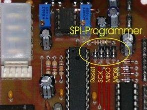
23: CIRCUIT:
24: Piezo Speaker connected to PortC pin PC7
25:
26: ADVANTAGES:
27: Pulse Width Modulation is not used in
28: this program.
29:
30: **********************************************/
31:
32: #define F_CPU 16000000UL
33:
34: #include <avr/io.h>
35: #include <util/delay.h>
36: #include <ctype.h>
37: #include <stdlib.h>
38: #include <stdio.h>
39:
40: #define SPEAKER_PORT PORTC
41: #define SPEAKER_DDR DDRC
42: #define SPEAKER_PIN 7
43:
44: // ——————————————-
45: // The classic British Postman Pat Tune:
46: // These are the program notes stored in a
47: // string. The string will be parsed.
48: // ——————————————-
49:
50: char tune[] = {“Postman Pat:d=4,o=5,b=100:16f#,
51: 16p,16a,16p,8b,8p,16f#,16p,16a,16p,8b,8p,16f#,
52: 16p,16a,16p,16b,16p,16d6,16d6,16c#6,16c#6,16a,
53: 16p,b.,8p,32f#,16g,16p,16a,16p,16b,16p,16g,16p,
54: 8f#.,8e,8p,32f#,16g,16p,16a,16p,32b.,32b.,16g,
55: 16p,8f#.,8e,8p,32f#,16g,16p,16a,16p,16b,16p,
56: 16g,16p,16f#,16p,16e,16p,16d,16p,16c#,
57: 16p,2d”};
58: // ——————————————-
59:
60:
61: // Arrays
62: char temp[4];
63:
64: // Prototypes
65: void
66: PLAYNOTE(float duration, float frequency);
67: // Defaults Parameters
68: int defaultlength;
69: int defaultoctave;
70: int beatspermin;
71:
72: // Variables
73: int length;
74: int octave;
75: float basenote;
76: float note;
77:
78: // Duration calculation.
79: float spb=0;
80: // seconds per beat.
81: float duration;
82: // Duration of the note.
83: float m=0;
84: // ‘.’ Multiplier.
85: float bpm=0;
86: // Beats per min.
87:
88: // Counters.
89: int c=0;
90: int pointer=0;
91:
92: int main(void)
93: {
94:
95: // Skip the music title
96: do{
97: pointer++;
98: }while(tune[pointer] != ‘:’);
99: // until ‘:’ reached.
100: pointer++;
101: // Skip ‘:’
102:
103:
104: // Extract the default duration
105: pointer++;
106: // Skip ‘d’
107: pointer++;
108: // Skip ‘=’
109: c = 0;
110: // Reset the array index.
111: do{
112: temp[c] = tune[pointer];
113: // Copy to a temporary array.
114: pointer++;
115: c++;
116: }while(tune[pointer] != ‘,’);
117: temp[c]=’\0′;
118: // Insert a null terminator.
119: defaultlength = atoi(temp);
120: // Convert the string to integer and
121:
122: // set “note duration”.
123: pointer++;
124: // Skip the comma.
125:
126:
127: // Extract the default octave.
128: pointer++;
129: // Skip 0
130: pointer++;
131: // Skip =
132: c = 0;
133: // Reset the array index.
134: do{
135: temp[c] = tune[pointer];
136: // Copy to a temporary array
137: pointer++;
138: c++;
139: }while(tune[pointer] != ‘,’);
140: temp[c]=’\0′;
141: // Insert a null terminator
142: defaultoctave = atoi(temp);
143: // Convert string to integer and
144:
145: // set “default octave”.
146: pointer++;
147: // Skip ‘,’
148:
149:
150: // Extract the beats per minute information.
151: pointer++;
152: // Skip ‘b’
153: pointer++;
154: // Skip ‘=’
155: c=0;
156: // Reset the index.
157: do{
158: temp[c] = tune[pointer];
159: // Copy to a temporary array
160: pointer++;
161: c++;
162: }while(tune[pointer] != ‘:’);
163: temp[c]=’\0′;
164: // Insert a null terminator.
165: beatspermin = atoi(temp);
166: // Convert the string to integer and
167:
168: // set beats-per-minute.
169: pointer++;
170: // Skip ‘:’
171:
172:
173:
174: do {
175:
176:
177: // Get the duration of the note.
178: if ((tune[pointer] == ‘3’) &&
179: (tune[pointer+1] == ‘2’)) {
180: length = 32;
181: pointer = pointer+2;
182: }
183: else if ((tune[pointer] == ‘1’) &&
184: (tune[pointer+1] == ‘6’)) {
185: length = 16;
186: pointer = pointer+2;
187: }
188: else if (tune[pointer] == ‘8’) {
189: length = 8;
190: pointer++;
191: }
192: else if (tune[pointer] == ‘4’) {
193: length = 4;
194: pointer++;
195: }
196: else if (tune[pointer] == ‘2’) {
197: length = 2;
198: pointer++;
199: }
200: else if (tune[pointer] == ‘1’) {
201: length = 1;
202: pointer++;
203: } else length = defaultlength;
204:
205:
206:
207: // ——————————————-
208: // Set the basenote to the correct frequency.
209: // Octave 4 is used here.
210: // Look for the # sharps first.
211: // ——————————————-
212:
213:
214: if ((tune[pointer] == ‘a’) &&
215: (tune[pointer+1] == ‘#’)) {
216: basenote = 466.164;
217: pointer = pointer+2;
218: }
219: else if ((tune[pointer] == ‘c’) &&
220: (tune[pointer+1] == ‘#’)) {
221: basenote = 554.365;
222: pointer = pointer+2;
223: }
224: else if ((tune[pointer] == ‘d’) &&
225: (tune[pointer+1] == ‘#’)) {
226: basenote = 622.254;
227: pointer = pointer+2;
228: }
229: else if ((tune[pointer] == ‘f’) &&
230: (tune[pointer+1] == ‘#’)) {
231: basenote = 739.989;
232: pointer = pointer+2;
233: }
234: else if ((tune[pointer] == ‘g’) &&
235: (tune[pointer+1] == ‘#’)) {
236: basenote = 830.609;
237: pointer = pointer+2;
238: }
239: else if (tune[pointer] == ‘a’) {
240: basenote = 440.000;
241: pointer++;
242: }
243: else if (tune[pointer] == ‘b’) {
244: basenote = 493.883;
245: pointer++;
246: }
247: else if (tune[pointer] == ‘c’) {
248: basenote = 523.251;
249: pointer++;
250: }
251: else if (tune[pointer] == ‘d’) {
252: basenote = 587.330;
253: pointer++;
254: }
255: else if (tune[pointer] == ‘e’) {
256: basenote = 659.255;
257: pointer++;
258: }
259: else if (tune[pointer] == ‘f’) {
260: basenote = 698.456;
261: pointer++;
262: }
263: else if (tune[pointer] == ‘g’) {
264: basenote = 783.991;
265: pointer++;
266: }
267: else if (tune[pointer] == ‘p’) {
268: basenote = 0;
269: pointer++;
270:
271: } else basenote = basenote;
272:
273:
274:
275:
276:
277: // If there is a number in the string then
278: // at this point it is always the octave
279: // scale numbers. Either, 4,5,6,or 7.
280: if (tune[pointer]==’4′){
281: octave=4;
282: pointer++;
283: }
284: else if (tune[pointer]==’5′){
285: octave=5;
286: pointer++;
287: }
288: else if (tune[pointer]==’6′){
289: octave=6;
290: pointer++;
291: }
292: else if (tune[pointer]==’7′){
293: octave=7;
294: pointer++;
295: } else octave=defaultoctave;
296:
297:
298: // Calculate the note based on the
299: // octave value
300:
301: if (octave == 4) {
302: note = basenote; //*1
303: }
304: else if (octave == 5) {
305: note = basenote*2;
306: }
307: else if (octave == 6) {
308: note = basenote*4;
309: }
310: else if (octave == 7) {
311: note = basenote*8;
312: }
313:
314:
315:
316: // When a period ‘.’ is found
317: // duration is x1.5
318:
319: if (tune[pointer] == ‘.’) {
320: m = 1.5;
321: pointer++;
322: } else m=1;
323:
324:
325:
326: // Calculate the duration.
327: bpm=beatspermin;
328: spb = 60/bpm;
329: duration=(spb/length)*1000*m;
330:
331:
332:
333: // Either play a note or pause for
334: // the time specified by duration.
335:
336: if (note == 0){
337: _delay_ms(duration);
338: } else
339: {
340: PLAYNOTE(duration, note);
341: }
342:
343:
344: // This is the pause between each note.
345: _delay_ms(spb*150);
346:
347:
348:
349: } while (tune[pointer++] == ‘,’);
350:
351:
352: }
353:
354:
355: // Function to play a note given
356: // the duration and frequency.
357:
358: void PLAYNOTE(float duration, float frequency)
359: {
360: // Physics variables
361: long int i,cycles;
362: float half_period;
363: float wavelength;
364:
365: wavelength=(1/frequency)*1000;
366: cycles=duration/wavelength;
367: half_period = wavelength/2;
368:
369:
370: // Data direction register: Pin 7 is
371: // set for output.
372: SPEAKER_DDR |= (1 << SPEAKER_PIN);
373:
374: for (i=0;i<cycles;i++)
375: {
376: _delay_ms(half_period);
377: SPEAKER_PORT |= (1 << SPEAKER_PIN);
378: _delay_ms(half_period);
379: SPEAKER_PORT &= ~(1 << SPEAKER_PIN);
380: }
381:
382: return;
383: // Return to main()
384: }
Read More Detail:RTTTL Player for the ATmega32


 motor drives the car as on the original circuit drive partition (sm6135w) used There is a simple transistor circuit .. schema, in addition to a distinct beauty of this pressure sensor circuit diagram drawings, source code through ATtiny2313 find. Also check ATtiny2313 floor designed as a simple set of experiments can use it in different projects, each floor of the circuit works ..