Quantcast
Channel: AVR ATmega Projects Archives - Projects Tutorials Code Library for Atmels Atmega32 AVR
Viewing all 1082 articles
Browse latest View live

USB POWERED INDUCTANCE METER CIRCUIT ATMEGA8

$
0
0

Coil measurement “Inductance Meter” circuit based on Atmega8 microcontroller LCD HD44780 driver and the system’s power supply is taken from the USB port on the computer or adapter operated with the circuit. Circuit of… Electronics Projects, USB Powered Inductance Meter Circuit Atmega8 “atmega8 projects, avr project, microcontroller projects, “

USB POWERED INDUCTANCE METER (1)

Coil measurement “Inductance Meter” circuit based on Atmega8 microcontroller LCD HD44780 driver and the system’s power supply is taken from the USB port on the computer or adapter operated with the circuit. Circuit of the box mints box cut and processed interesting metal, enamel paint made circuit optimized 🙂

The LCD screen of the circuit 10MHz frequency coil over strut value is displayed in the Information, as well as the frequency.

Coil measurement circuit’s eagle pcb, diagram drawings are ATMega8 source and hex code.

USB POWERED INDUCTANCE METER (2)

USB POWERED INDUCTANCE METER (3)

Source: http://rototron.info/ alternative link: usb-powered-inductance-meter-circuit-atmega8.rar


ATMEGA32 LED CUBE CIRCUIT 74HCT238

$
0
0

On the Internet, atmel, microchip series microcontrollers with a lot Led cube has a project in this application one of them, but diagrams, photos, supplemented with a detailed description there thanks to this project…Electronics Projects, Atmega32 LED Cube Circuit 74HCT238 “avr project, led projects, microcontroller projects, “

LED CUBE CIRCUIT (1)

On the Internet, atmel, microchip series microcontrollers with a lot Led cube has a project in this application one of them, but diagrams, photos, supplemented with a detailed description there thanks to this project Led cube understand the logic may be easier to floors circuit diagram and C source software provided.

5x5x5 LED cube dimensions 512 x red leds placement of the LEDs will be a bit erratic but it has involved a lot of precise soldering LEDs 🙂

Led cube of the main materials used in the circuit outside ATmega32 CD74HCT238 decoder and 74LS04 Hex Inverter

LED CUBE CIRCUIT (2)

LED CUBE CIRCUIT (3)

Source: people.ece.cornell.edu alternative link: atmega32-led-cube-circuit-74hct238.rar

HDD BRUSHLESS MOTOR DRIVER CIRCUIT ATMEGA8

$
0
0

Brushless motor drive circuit used in computers hard drive with Atmega8 checked the engine ATmega 8 output MOSFET (IR4427, IRFZ44) strengthened engine with A, B, C, D, attached to either end. Software is written… Electronics Projects, HDD Brushless Motor driver Circuit Atmega8 “atmega8 projects, avr project, microcontroller projects, “

HDD BRUSHLESS MOTOR DRIVER (1)

Brushless motor drive circuit used in computers hard drive with Atmega8 checked the engine ATmega 8 output MOSFET (IR4427, IRFZ44) strengthened engine with A, B, C, D, attached to either end. Software is written in C language compiler used in CV AVR application circuits for frequency crystal oscillator is used but instead of the internal crystal oscillator recommend testing for long-term operation of the motor is estimated that 30,000 of cycles.

HDD BRUSHLESS MOTOR DRIVER schamatic

Source: http://avrlab.com/ alternative link: hdd-brushless-motor-driver-circuit-atmega8.rar

RGB LED EXAMPLE CIRCUIT ATMEGA88 ATMEGA8 ATMEGA48

$
0
0

White LEDs, blue LEDs, ultra bright LEDs RGB LEDs saying quite a lot in the sample application with popular microcontrollers are used in this circuit, atmega8 ATMEGA48 Atmega88 ATmega output MOSFETs are driven by… Electronics Projects, RGB Led Example Circuit Atmega88 Atmega8 Atmega48 “atmega8 projects, avr project, led projects, microcontroller projects, “

RGB LED EXAMPLE CIRCUIT (1)

White LEDs, blue LEDs, ultra bright LEDs RGB LEDs saying quite a lot in the sample application with popular microcontrollers are used in this circuit, atmega8 ATMEGA48 Atmega88 ATmega output MOSFETs are driven by LEDs in the C language prepared by the software. Also prepared by isis proteus simulation is in the drawing.

RGB LED EXAMPLE CIRCUIT (2) RGB LED EXAMPLE CIRCUIT (3)

Source: https://320volt.com/en/atmel-atmega-rgb-led-ornegi-mosfet-surucu/ alternative link: rgb-led-example-circuit-atmega88-atmega8-atmega48.rar\


LED EFFECT CIRCUIT ATTINY2313 MULTI FUNCTION

$
0
0

Led effect circuits, including myself, a lot of people might be interested, especially this sort LEDs and LED circuits have great interest in blue, white, LED prices now old and not so expensive LED… Electronics Projects, Led Effect Circuit Attiny2313 Multi Function “avr project, led projects, simple circuit projects, “

LED EFFECT CIRCUIT (1)

Led effect circuits, including myself, a lot of people might be interested, especially this sort LEDs and LED circuits have great interest in blue, white, LED prices now old and not so expensive LED effect circuit 12 LEDs used effects transition and speed adjustment buttons is done with used microcontroller ATtiny2313

Circuit source. Bass. Hex,. Thousand source code and sprint pcb printed circuit board layout drawings I have prepared with 5.

LED EFFECT CIRCUIT (2)

all files: led-effect-circuit-attiny2313-multi-function.rar

Alternative File Download LINK list (in TXT format): LINKS-15462.zip

15A MOTOR SPEED CONTROL CIRCUIT ATTINY45 PWM

$
0
0

Used in motor speed control circuit microcontroller atmel attiny45p exit number 5 Kubla connected to pin opto pc817 pc817 output while the engine is controlled as isolated MOSFETs have bs170 and irlz34 Attiny45 Pb4… Electronics Projects, 15A Motor Speed Control Circuit Attiny45 PWM “avr project, microcontroller projects, pwm circuits, “

15A MOTOR SPEED CONTROL CIRCUIT (1)

Used in motor speed control circuit microcontroller atmel attiny45p exit number 5 Kubla connected to pin opto pc817 pc817 output while the engine is controlled as isolated MOSFETs have bs170 and irlz34 Attiny45 Pb4 leg control signal number 3 is entered. Circuit driven by motors up to 15 amps. MOSFETs are driven by PWM method pwn frequency 1.8 kHz

Attiny45 LM2940CT5 regulator used to supply PWM motor control Attiny45 value you can use the 7805 Bascom project’s source code schema, and PCBs have drawings

15A MOTOR SPEED CONTROL CIRCUIT (2) 15A MOTOR SPEED CONTROL CIRCUIT (3)

Source: rc-schottel.ch Dosyalar: 15a-motor-speed-control-circuit-attiny45-pwm.rar

ATMEGA16 LEDS SNOW EFFECT CIRCUIT LED SNOW CRYSTAL

$
0
0

It really is a great led light application LEDs so fluently is moving a profit crystalline with mold has been excellent ATMega16 microprocessor 32 Edet output used to all the LEDs griplar connected software…Electronics Projects, ATMega16 LEDs Snow Effect Circuit LED snow crystal “avr project, led projects, microcontroller projects, “

LEDS SNOW EFFECT CIRCUIT

It really is a great led light application LEDs so fluently is moving a profit crystalline with mold has been excellent ATMega16 microprocessor 32 Edet output used to all the LEDs griplar connected software BASCOM-AVR 1.11.9.0 prepared with all encode scheme molded case also sprint layout pcb drawing is on.


Source: lightportal.at.ua alternative link: atmega16-leds-snow-effect-circuit-led-snow-crystal.rar


LED PROPELLER CIRCUIT AT90S2313 ATINY2313

$
0
0

Printed circuit board layout pcb design effects with LEDs been a good practice to work in the dark when used with an ultra bright LEDs looks very nice. Atmel AT90S2313 64 LEDs instead of… Electronics Projects, Led Propeller Circuit AT90S2313 ATINY2313 “avr project, led projects, microcontroller projects, “

LED PROPELLER CIRCUIT (1)

Printed circuit board layout pcb design effects with LEDs been a good practice to work in the dark when used with an ultra bright LEDs looks very nice. Atmel AT90S2313 64 LEDs instead of creating Propeller microcontroller TINY2313 BASCOM-AVR 1.11.9.1 prepared with available software sprint pcb layout drawing and drawing spline scheme has the source code.

Source: lightportal.at.ua alternative link: led-propeller-circuit-at90s2313-atiny2313.rar


LED HEART CIRCIUT ATMEGA88

$
0
0

Atmel atmega88 PCB LEDs circuit drawing heart looks great, especially boxing PCAD pcb drawings and diagrams and drawings prepared by the C source code files have a heart-shaped 22 pcs SMD LED flashes with… Electronics Projects, Led Heart Circiut ATmega88 “avr project, led projects, microcontroller projects, “

LED HEART CIRCIUT (1)

Atmel atmega88 PCB LEDs circuit drawing heart looks great, especially boxing PCAD pcb drawings and diagrams and drawings prepared by the C source code files have a heart-shaped 22 pcs SMD LED flashes with different effects at work lined up

Author of the box lid is opened to operate the circuit embodiment has set

LED HEART CIRCIUT (2)

Source: habrahabr.ru alternative link: led-heart-circiut-atmega88.rar

AUTOMATIC RABBIT FEEDING SYSTEM ATMEGA8 TIMER

$
0
0

In fact, feeding, feeding various timing circuits used for business. Generally puzzling, time-consuming mechanical parts is getting no special circuitry to rabbits in this project but the authors have used to feed rabbits :)… Electronics Projects, Automatic Rabbit Feeding System ATmega8 Timer “atmega8 projects, avr project, microcontroller projects, “

AUTOMATIC RABBIT FEEDING SYSTEM (1)

In fact, feeding, feeding various timing circuits used for business. Generally puzzling, time-consuming mechanical parts is getting no special circuitry to rabbits in this project but the authors have used to feed rabbits 🙂 crafted with a software pascal Pascal example might be for users.

Circuit based on Atmel ATmega 8 2 × 16 LCD also displays information on the source code of the circuit prepared with eagle pcb, diagram drawing there.

AUTOMATIC RABBIT FEEDING SYSTEM (2) AUTOMATIC RABBIT FEEDING SYSTEM (3)

Source: silicium628.fr alternative link: automatic-rabbit-feeding-system-atmega8-timer.rar


CURRENT MEASUREMENT DATA LOGGER CIRCUIT ATMEL AVR, PIC

$
0
0

Very high current of the current transformer and with microcontroller sensitive way measured to be recorded will be useful for source code with 2 sample application circuits one of the Atmel AVR ATMEGA48 88/168-P…Electronics Projects, Current Measurement Data Logger Circuit Atmel AVR, PIC “avr project, microcontroller projects, “

CURRENT MEASUREMENT DATA LOGGER

Very high current of the current transformer and with microcontroller sensitive way measured to be recorded will be useful for source code with 2 sample application circuits one of the Atmel AVR ATMEGA48 88/168-P used) based on the current (4kW) information on the SD card is able to record and chart GLCD the circuit can also view information on LMC6484A, ADE7757, AD623 used in the entegreleri

Other applications made by the software pic16c74 prepared with CCS C program via the PC displays current information

CURRENT MEASUREMENT DATA LOGGER (1)

This device monitors household power usage and logs it to an SD card. A simple analog front-end amplifies the signals from voltage and current detectors and an ATmega168 microcontroller computes the power consumption using the formula P=V*I. voltage divider connected to an AD623AN instrumentation amplifier. LMC6484AIN quad op-amp is used for signal amplification.

Power Line Monitor power is calculated with an analog multiplier followed by a low pass filter to obtain the DC component (real power). These analog quantities are then fed to a 12-bit A/D converter driven by a ’77 PIC. The circuit gains get me a resolution of 5 Watts. As a result I can even see the effect of turning on one lamp.


Source : current-measurement-data-logger-circuit-atmel-avr-pic.rar

LABORATORY ADJUSTABLE 0-24V DIGITAL POWER SUPPLY CIRCUIT ATMEGA8

$
0
0

Power supply circuit two separate sections consisted primarily power solid LM317 based on the current settings for the tl082 opamp used current voltage display section Atmel ATmega8 microcontroller used optionally this section may not… Electronics Projects, Laboratory Adjustable 0-24v Digital Power Supply Circuit ATMega8 “atmega8 projects, avr project, microcontroller projects, “

DIGITAL POWER SUPPLY CIRCUIT

Power supply circuit two separate sections consisted primarily power solid LM317 based on the current settings for the tl082 opamp used current voltage display section Atmel ATmega8 microcontroller used optionally this section may not be used completely independently of various circuits to try, simple to run a power supply

DIGITAL POWER SUPPLY CIRCUIT (1) DIGITAL POWER SUPPLY CIRCUIT (2) DIGITAL POWER SUPPLY CIRCUIT (3) DIGITAL POWER SUPPLY CIRCUIT (4)

DIGITAL POWER SUPPLY CIRCUIT (5)

Source link: laboratory-adjustable-0-24v-digital-power-supply-circuit-atmega8.rar

ILI9325 TOUCH-SCREEN PROJECT TFT ATMEGA644 ELT240320ATP

$
0
0

Atmel is a great project with a series of applications can be made super graphics used in this project Atmega644 the ELT240320ATP GLCD (320 × 240) driver ILI9325 Simple as iPhone menu has pacman…Electronics Projects, ILI9325 Touch-Screen Project TFT Atmega644 ELT240320ATP “avr project, microcontroller projects, “

TOUCH-SCREEN PROJECT TFT

Atmel is a great project with a series of applications can be made super graphics used in this project Atmega644 the ELT240320ATP GLCD (320 × 240) driver ILI9325

Simple as iPhone menu has pacman game image representation, 3d varied menu and a lot more features there Atmega644 12MHz and operated micro sd card usb mouse keyboard hidden features such as it’s source code as well as the eagle pcb, diagram drawing given in.

support for ssd1297 lcds. these are found in a number of touch lcd players,
including the first version of the sylvania player. they are marked “ssd1297”.
define ssd1297 in lcd.cpp or the makefile.

important: the ssd1297 lcds have pin 11 and 21 connected to gnd. the 1v1 pcb has
these ‘nc’ pins connected to vcc. if you use a ssd1297 cover these pads with
kapton or non conductive tape or blue smoke will waft our of the device.

mmc fix for over-optimized code that failed on many manufacturers cards.

Suport for USB Hid and C# application for experimentation. A quick and dirty hack using Christian Starkjohann’s great USB code. The RossumUtil app exercises the connection, allows you to connect to the device, draw rectangles, blink leds etc. Enable with USE_HID define in Microterm.cpp.


Source: http://rossum.posterous.com/avr-homebrew-device-with-iphone-aspirations alternative link: ili9325-touch-screen-project-tft-atmega644-elt240320atp.RAR

LED ANIMATION CIRCUIT ATMEGA168

$
0
0

Last year in one of my classes we were required to make an ‘artefact’ or something that reflects the interests of the class. Most people make posters and the past two quarters that’s what my class did too. Posters however are static, usually boring, and don’t reflect that fact that everyone in the class is an EE major. We decided posters are for noobs and decided to go off the wall a little and make an LED matrix display. Lucky one of my friends John Wathen already had this beautiful 16×24 Green SMD LED matrix that he built back in high school.

LED Matrix (1)


LED Matrix (2)

What we didn’t have however was a driver for it. The driver we choose to design was highly inspired from this one. The basic idea is that you use shift registers to sink the columns and a line driver of some sort to source the rows (we chose to use a Darlington array).

There where a lot of changes from the Instructables design that that we had to make however. The matrix in the Instructables was a lot smaller than ours and used 8 IO lines to drive each row. Since our matrix has 16 rows this was completely infeasible using just an ATMega168. To solve this issue we choose to use a 4:16 de-mux to control all sixteen rows with only 4 IO pins. The de-mux combined with two 8 channel Darlington arrays provided the perfect interface to control all 16 rows. To sink the columns we choose to string three 8 Output shift registers. Each shift register is rated to handle the current of the 8 LEDs that could possibly be on at one time.

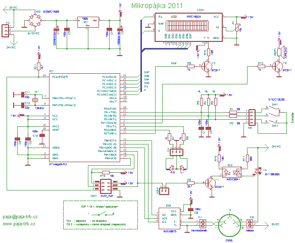
Some other features that we included on the driver board were 3 green LEDs, 3 push buttons, ISP header, TTL header. When all was said and done we ended up the the schematic shown below.

LED Matrix schamatic (3)


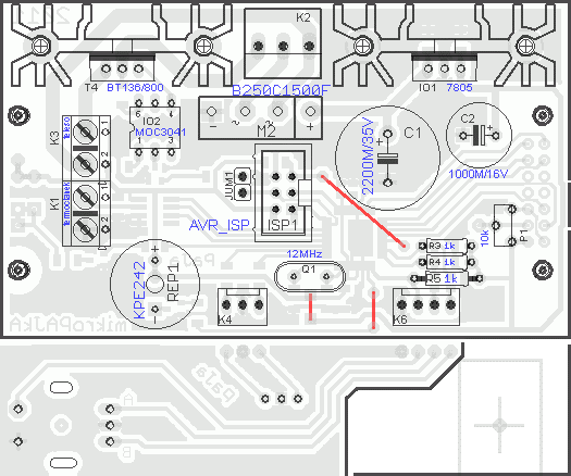
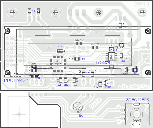
I know, you are probably looking at that and thinking, “Why are all the shift register outputs criss-crossed??”. The reason for doing this is because the output pins on the chip are not exactly in a row so to assist in board layout the pins had to be crossed and mixed up so that the board layout would be nice. It’s much easier to change the order of the columns in the program then it is on the board layout (in my opinion). We didn’t want to etch a double sided board so a lot of effort went into laying as much of the circuit out on a single side. There were a few paths that could not be routed and were just jumped with wire (you’ll see in picture below).
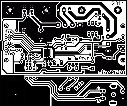
LED Matrix schamatic (4)


Notice how there are a bunch of air-wires (yellow lines) that I couldn’t figure out how to route, they are manually jumped when the board is put together.

To etch the board we printed out the board layout 1:1 scale on glossy photo paper, it was than ironed onto a piece of copper clad. The idea is that the toner will stick to the copper clad and when the board is dipped in acid the acid will eat away at everything but the traces, since they are coved by the toner. I’m definitely not an expert in this area so ask John Wathen more about the process, he is basically a pro.

Etching the board in acid (1)
Etching the board in acid
 

Checking to see if its ready to be scrubbed (2)
Checking to see if its ready to be scrubbed
 

Dirty traces
Dirty traces
 

Scrubbing off the rest of the toner
 

The beautiful result, nice and shiny

Now, let me just tell you that we did this in a public bathroom at school. So there were three guys in a bathroom with latex gloves, a camera, and tub of some green liquid. Trust me we got some weird looks.

The next step was to drill all the holes. I don’t remember exactly how many there were (John might) but there were a lot.

LED Matrix (10)


After all the holes were drilled John soldered it all up.

LED Matrix (11)


LED Matrix (12)


And the result!

LED Matrix (13)
LED Matrix (14)

LED Matrix (15)

LED Matrix (16)

LED Matrix (17)

LED Matrix (18)

LED Matrix (19)

LED Matrix (20)

LED Matrix (21)

LED Matrix (22)

Now that the board was finished it was the moment of truth.

Adam Steele lent me his programmer. Plugged it into my Xbuntu box, apt-get installed the avr tool-kit and the programmer was immediately recognized (NICE!). Flashed a simple program to flash the status LEDs and low and behold, IT WORKED! Next up, everything else. I started by modifying the program that the Intructables provided but quickly got frustrated by the way it worked. It treated each column as a bit in a byte and the rows as a byte, this made it extremely hard to visualize outputs to the display. Also I was using a de-mux and had 24 columns which the code did not easy support. So what do you do in this situation? REWRITE.

An outline of how the new code works:

The value for each pixel is stored in a 2D array 16×24, want to set the top left pixel? buffer[0][0] = 1; simple as that, much easier than dealing with it as an array of bytes. Okay, so it takes up more memory but IMO it is completely worth every bit (pun intended).

The code starts by initializing the ports (pull-ups, in/out, etc) then it initializes timer1. To be completely honest the fill value for the timer was chosen by adjusting value, flashing, seeing if the refresh rate was noticeable. We ended up with OCR1A = 0x012C; as a good value.

The code then falls into an While(1) where it sequentially calls functions to draw stuff on the screen, for example:

Spiral(5, 0);

Tunnel(1);
Tunnel(0);
Tunnel(1);

Erase_Rider(RIGHT, 10);
Fill(LEFT, 10);

Shift(UP, 16, 50);

Erase_Rider(DOWN, 10);
Er

All the high level functions (tunnel, spiral, shift, etc..) write to ‘buffer’. When the timer interrupt goes off it calls the function shift_int() which reorders the columns into ‘buffer_2’ and then shifts them out to the shift registers. It then calls shift_mux() which jumps to the next row. So essentially we have a double buffered display.

Once all the low level code was done it was all fun and games. It was really nice being at the point were all you had to work with is a 2D array. We ended up with the high level functions:

void Delay_ms(int cnt)
void Clear_Display(void)
void Fill_Display(void)
void Flash_Display(u8 cycles, u8 speed)
void Col(u8 col, u8 state)
void Row(u8 row, u8 state)
void Fill_Col(u8 col, u8 dir, u8 speed, u8 state)
void Fill_Row(u8 row, u8 dir, u8 speed, u8 state)
void Fill(u8 dir, u8 speed)
void Invert_Col(u8 col)
void Invert_Row(u8 row)
void Invert_Fill(u8 dir, u8 speed)
void Erase_Rider(u8 dir, u8 speed)
void Spiral(u8 speed, u8 state)
void Tunnel(u8 state)
void Invert(u8 count, u8 speed)
void Draw_Line(u8 x1, u8 y1, u8 x2, u8 y2, u8 state)
void Shift(u8 dir, u8 amount, u8 speed)
void Scroll_Char (char myChar, u8 pos, u8 dir, u8 speed)
void Box(u8 speed, u8 dir, u8 state)
void Grid(u8 speed, u8 state)

It is so incredibly easy to make new functions when you are just manipulating a 2D array.

A warning before you watch the videos, they were taken with a crappy point n shoot camera so they look incredibly choppy. In real life the display is incredibly fluid and smooth. The videos do it zero justice.

Source: http://bear24rw.blogspot.com alternative link: led-animation-circuit-atmega168.RAR

FAST FOURIER TRANSFORMATION FFT CIRCUIT ATMEGA8 SCT2024 LED DRIVER

$
0
0

ATmega8 (TQFP32 package) based on FFT Circuit applied the entry signals 16 × 16 led display (SCT2024 serial-interfaced LED driver 256 LEDs), you can see in the FFT circuit source C, hex codes have… Electronics Projects, Fast Fourier transformation FFT Circuit ATmega8 SCT2024 LED driver “atmega8 projects, avr project, microcontroller projects, “

FAST FOURIER TRANSFORMATION FFT CIRCUIT

ATmega8 (TQFP32 package) based on FFT Circuit applied the entry signals 16 × 16 led display (SCT2024 serial-interfaced LED driver 256 LEDs), you can see in the FFT circuit source C, hex codes have a parent/child schema for the printed circuit drawings a good example about the use of the SPI, ADC with atmega8

FAST FOURIER TRANSFORMATION

fast Fourier transform (FFT) is an algorithm to compute the discrete Fourier transform (DFT) and its inverse. Fourier analysis converts time (or space) to frequency and vice versa; an FFT rapidly computes such transformations by factorizing the DFT matrix into a product of sparse (mostly zero) factors. As a result, fast Fourier transforms are widely used for many applications in engineering, science, and mathematics. The basic ideas were popularized in 1965, but some FFTs had been previously known as early as 1805. Fast Fourier transforms have been described as “the most important numerical algorithm of our lifetime”.

FAST FOURIER TRANSFORMATION FFT CIRCUIT (1)

FAST FOURIER TRANSFORMATION FFT CIRCUIT (2)

FAST FOURIER TRANSFORMATION FFT CIRCUIT (3)

Source: http://hw.cz/ all files: fast-fourier-transformation-fft-circuit-atmega8-sct2024-led-driver.ZIPalternative link2


24V 48W DIGITAL SOLDERING STATIONS ATMEGA8

$
0
0

After a year of using my assembled Microfibers according to the Jendy documents23 , I decided to build DIGITAL SOLDERING STATIONSanother (third) microfuel.
I wanted to reduce the dimensions, use the 24V AC heating power, to adjust the temperature better and to add additional functions …

Features of micro-drives :

  • temperature range 80 ° C to 450 ° C
  • continuous regulation of heating and temperature reading 3x per second
  • stand-by mode with a holding temperature of 120 ° C and off LCD backlighting
  • possibility of fast temperature setting – jumping after 50 ° C
  • acoustic signaling of reaching the temperature during first warm-up, operating states, tip disconnection
  • piezo can be switched off
  • watch the delayed hand in the stand (can be switched off), after 10, 12, and 14 min sound alert, turn off the heater and backlight (auto-off) after 15 minutes. You can only wake up by pressing the button
  • temperature overtemperature monitoring – or fault-disconnection of the thermocouple
  • temperature probe calibration (multiplying measured temperature 0.9 to 1.1)
  • all settings (and temperatures) are stored in Eeprom and are active even after the solder is switched on again

Features :
The 12V AC from the transformer is straightened and stabilized at 5V for CPU and electronics.
24V AC is switched via opto-triax IO2 (with zero switching) and triac T4 for heating the body of the handpiece.
The temperature reading from the thermocouple is in charge of the IO6 MAX6675, from which the processor reads the actual temperature, adjusts it and adjusts the heating of the body according to the settings, displays the temperature on the display, the two-color LEDs, monitors the inputs from the rotary encoder and activates the piezo …
The diagram shows a delayed-release watch switch in a stand that is connected to the ISP connector (instead of the programmer) between pins 1 and 6 (the flat cable’s terminals). If the hand is in the stand – the switch is closed. The switch does not need to be used, the microswitch will work without it.

Construction :
Since the design I tried to place everything on one PCB with minimal connections and wires … so the display is connected from the side of the connections through the precise breaking connectors – saving the number of wires to connect to the electronics board.
The transformer is the original Solomon soldering iron spare part, but just plug the plug from the second transformer into the PCB.
Only the main board and the feed to the rot can be used during construction. encoder and LED to solve PSH02 connectors or make a wider version with wired connection of both boards and LED and rot. encoder from the side of the links (seeing the correct height).
Short jump – Jumper does not need to be fitted – it replaces wire jumper or SMD zero resistor. I only used to test and disable body heating when programming (but there is no problem programming the processor with the jumper).

When making the box, I was inspired by the previous version. I have just achieved half the dimensions of 165mm x 100mm and 95mm height.
The front, bottom and rear parts are made of one piece of 2mm aluminum sheet. On the bottom part, for the fixing and securing of the side walls, 2 pieces of duralumin vingles 15x15mm. At the front (under the electronics) there are a couple of holes for ventilation.
The hips and the top are made of galvanized sheet metal, above the sponge bowl.
I also added a few holes for the better cooling on the side of the top, especially the 7805 cooler heats up and overheats the inside of the box.
I purchased the ZD-10A soldering iron stand , slightly adjusted the hold to raise the handle when the handle was inserted and open the microswitch (see photo ). This adjustment is unnecessary – the solder will work without a hand-held delay – not a functional auto-off.
The 230V AC supply is designed via a PC socket with a built-in tube fuse holder (sufficient 1A), the phase is switched via the switch on the front side to the primary port.
I printed the label on the front of the self-adhesive paper, cut the display window and sealed it with a transparent self-adhesive foil (the display window with a piece of foil on the other side – and the dust would not stick to the adhesive). The weight of the microfibers is less than 2kg.

Consumption :
Primary transformer (measured with a 20-meter multimeter) : melts = 0.25A / cold = 0.06A / stand-by = 0.05A
Consumption of money for construction … about 1400kč for electrical material. I do not count the iron for the construction of the box and the countless hours of production.

Program :
At the same time holding the button down and turning on the solder, you can get to calibrate the actual measured temperature at the end of the tip (the thermocouple with the meter over a drop of molten tin at the tip of the tip) . Because the read and “real” can vary slightly, it is possible to multiply the loaded temperature by 0.9 to 1.1
For this purpose, the graph is converted from Excel: Calibration Deviation Calculation . After entering the measured values compared to the display (before calibration it is good to set the calibration to 1.0 !!!), then excel calculates the multiple of the measured value – the calibration deviation.
The first step after switching on is to check the temperature, if it is less than 80 ° C, automatically switches on the heater, beeps and displays on the display of Pajea station / PaJa after 1s microPaJka / 2011 v1.5 .
From this moment, the program runs in an infinite loop and interrupts it 3 times / second Timer1, which checks for the delay of the hand and the state of the microtarget – mode of operation / stand-by
Operation – reads the temperature, calculates the deviation of the set and loaded temperature. First warm up on setting. the temperature is blinking, otherwise the LED flashes according to the regression and maintains the temperature by heating the body. The display shows the set and actual tip temperature, and if the tip temperature is exceeded (> 700 ° C = disconnect / fault), the alarm sounds and displays the Disconnected warning. Small thermometers on the sides of the display vary depending on the set and reached tip temperature (regression deviation)
Stand-by – backlight goes off, displays stand-by / 120 ° C , reads and maintains the tip temperature at 120 ° C
The MAX6675 temperature readout runs in series, then the 16-bit value moves to the right by 5 positions to obtain temperature information in ° C. The temperature is further adjusted to the calibration value and converted to the appropriate type of variable.
Encoder – in the case of rotating rot. the encoder activates an external interrupt and the program serves it. Check the condition of the second pin rot. encoder. By adding or subtracting the set temperature, the resulting value will be stored in the memory (preserved after the solder has been switched off) and displayed on the display.
Button – Second external interruption when the rot button is pressed. encoder. It stops Timer1 (3x / s will not interrupt). It then monitors the length of the keystroke and either switches the Operation / Stand-by mode or, when pressed for a longer time, jumps to the Menu, then reactivates Timer1
Menu – stops Timer1 and disables both external interruptions. The first menu item is to quickly set the temperature to 50 ° C (range 80-450 ° C) by pressing. the value is stored. Another is to allow / disable pieza and the last is to watch the delay of the hand. Finally, it will re-enable Timer1 and both external interruptions.

DIGITAL SOLDERING STATIONS schamatic
Here is the design of a printed circuit board of microfibers with dimensions (main board) 88 x 52 mm. DIGITAL SOLDERING STATIONS (2) DIGITAL SOLDERING STATIONS (3)

DIGITAL POWER SUPPLY CIRCUIT (3)

List of used components:

R1, R2 – 33 SMD vel.0805
R3-R5 – 1k
R6,7,9,12 – 1k SMD size 1206
R8 – 2k7 SMD size 1206
R10-10 SMD size 1200 (or similar 5-15 ohm)
R11 – 4k7 SMD vel.1206
R13 – 10k SMD vel.1206
R16 – 180 SMD size 1206
R17 – 360 SMD size 1206
P1 – 10k Trim PT6H (Standing) C1 – 2200M / 35V (RM7,5)
C2 – 1000M / 16V (RM5)
C3-C8 – 100n SMD size 1206
C9, C10 – 100n SMD vel.0805
C11, C12 – 22p SMD size 1206
D1 – LED 5mm – red + green, spol. cathode
M2 – B250C1500F or KBL04 (TME)

LCD1 – PRC1602A LCD display 2×16 with backlight or RC1602D (TME)
IC1 – ATmega8-16AU
IO1 – 7805 + Heatsink HS-135A-38 (TME) – Best even bigger
IO2 – MOC3041
IO6 – MAX6675 SMD (from: MAX6675 TME)
Q1 – 12MHz
REP1 – KPE242
SW1 – STEC12E08 (rotary encoder with SOS button) + hat

T1-T3 – BC817 SMD SOT-23
T4 – BT137 / 800 + Heatsink HS-135A-38 (TME)
ISP1 – MLW06G
JUM1 – S1G2 + JUMP (can be connected by wire or zero SMD resistor)
K1, K3 – ARK500 / 2
K2 – PSH04-03P
K4 – PSH02-03P
K6 – PSH02-04P

PENSOL-SL20-T (TME) – Transformer to PENSOL SL10 and 20, SL10ESD, 20ES
PENSOL-IRON-N (TME) – Solomon soldering iron handpiece + DIN-5 connector
wire jumper (bridge) – a piece of wire – 3x

Source: http://paja-trb.unas.cz/elektronika/konstrukce/mikropajka_2011.html alternative
link: 24v-48w-digital-soldering-stations-atmega8.RAR

SMART REMOTE ATMEGA88 CIRCUIT COPY THE TWO BUTTONS

$
0
0

This fun project lets you take control away from the person holding the remote control by intercepting the invisible signals as they travel through the air so you can play them back to the TV or video machine. You can also “train” your Remote Hijacker by recording certain button presses directly from the remote so that you can play them back later on, taking total control over the target appliance. Because this project records the remote control pulse stream directly, it will work on any infrared based remote control, able to learn a few button presses.

SMART REMOTE ATMEGA88 CIRCUIT

This project uses a very simple microcontroller program that just times the pulses coming into the infrared decoder and then stores them in the internal SRAM for later playback. The source code is made as simple as possible, allowing for plenty of room for modifications and alterations to suit your evil genius agenda. Because no interrupts are used, the C program could be ported to just about any microcontroller, and will work on all of the Atmel microcontrollers as is. Larger internal memory allows more button presses to be stored, with the Amtega88 (1K SRAM) allowing about three button presses to be recorded and played back.

remote Hijacker Control Parts List

remote control signals first decoded by the RC5 module

Almost every electronic appliance that includes an infrared remote control will use a standard method of communication over the invisible beam called the “RC5 Protocol”. This simple protocol works by sending a series of 1.5ms to 2.5ms long pulses that are modulated by a carrier frequency of 36 KHz to 45 KHz. The pulses make up a frame of data, which is usually 12 bits long, encoded using a system of inversion called Manchester Encoding. Of course, we won’t have to dig all that deep into any of this stuff because this project just records the length of pulses and stores them as byte values into the microcontroller’s internal memory for later playback.

Of course, you could actually decode the data and store a lot more, but this would require some crafty programming to measure the exact pulse rate and then understand the stream that it is seeing at the input. I just wanted a quick and dirty hack that would allow me to prank the remote control user, so I opted to just measure the time between pulses and store that value. This allows any remote to be recorded and played back as the program does not care what the exact frequency or command being sent really is.

To deal with the very fast 40 KHz modulation, a readymade solution is used that will strip out the modulation and leave only the millisecond pulse train. These remote control decoder modules are very common as they are used in most of the appliances that we are going to hijack. These tiny 3 pin blocks have a power, ground, and output, and do nothing more than look for RC5 pulses in order to strip them of their modulation. I have collected many of these remote control modules from various dead appliances and electronics suppliers, and all of them do basically the same thing. Some of them are contained in a metal can, while others look like transistors with a bubble on one side to input the infrared light. All that matters is that you can figure out which pins are power, ground, and output on the device.

Source: http://www.lucidscience.com/pro-remote%20hijacker-1.aspx Alternative link: smart-remote-atmega88-copy-the-two-buttons.rar

FREQUENCY METER CIRCUIT LCR METER ATMEGA328

$
0
0

I have been thinking about building an LC meter for a while since I do not have a multimeter that is capable of measuring inductance and while the multimeters I have can measure capacitance, they are not able to give accurate readings for small capacitance in the range of several pF’s.

There are quite a few good articles on how to build LC meters using PIC MCUs (like the ones here: 123), but instructions on how to build one with an ATmega MCU are few and far in between, although the basic principle is largely the same. So I decided to write this article on how to build an LC meter using an ATmega328p chip and Arduino libraries.

A typical LC meter is nothing but a wide range LC oscillator. When measuring an inductor or capacitor, the added inductance or capacitance changes the oscillator’s output frequency. And by calculating this frequency change, we can deduce the inductance or capacitance depending on the measurement.

The following schematic shows the comparator based LC oscillator I used in the LC meter. The oscillator portion is quite standard. Most of the other designs I have seen use LM311 comparator. But for this type of application, any comparator capable of oscillating up to 50kHz should be more than sufficient. I happen to have some spare LM339’s lying around so I used it in the oscillator circuit.

LC Meter - Oscillator

Note, there should be a 3K pull up resistor on pin 1 and the feedback resistor should be 100K instead of 10K.

Because what we are really meausring is the frequency of the oscillator, we can build a frequency meter using the same circuit at almost no additional cost. As you can see in the circuit above, a reed relay is used to switch the measurement from LC mode to frequency mode. In the schematics above, the second comparator forms a Schmitt trigger to condition the input waveform so that the frequency measurement can be made more accurate. When in the LC mode, the frequency output from the first comparator is simply feed through the Schmitt trigger. The output frequency is determined by

f0=1/2LC 

where

L=L0+Lmeasured

and

C=C0+Cmeasured

Choosing a high accuracy L0 and C0 helps improve the accuracy of the meter.

Here’s the MCU side of the schematics:

LC Meter

This circuit is capable of measuring inductance in a wide range, from a few nH all the way up to a few Henrys. For capatance measurement, I have found that it is most suitable for measurement from a few pF to tens of nF. You maybe able to measure slightly larger capacitors if they have a high ESR rating. But this range limit in capacitance measurement should not be an issue as what we care most about is the accuracy in the pF range.

I used this frequency library for the frequency measurement. By default, the display is updated every second. This mode provides the most accurate result. You can shorten this update interval easily, but the measurement accuracy will be reduced.

The Arduino code for this project can be downloaded here (LCFrequencyMeter.zip). This project was developed using the NetBeans IDE and you may need to adjust the included header files if you are using Arduino IDE. For more information, please see my previous article on this topic.

The calibration method I used is like this: in capacitance measurement mode, the none-load reading is used to calculate stray inductance (assume that C0 is accurate) which is then used to compensate capacitance measurements. And similarly, in inductance measurement mode, we assume that L0 is accurate and the none-load reading (by shorting the test leads) is used to calculate stray capacitance which is then used to compensate inductance measurements. If you read through the code you will get a better idea on how this is done.

The following picture shows the capacitance reading when using this meter to measure a known 2.22nF capacitor:

Capacitance Measurement

Capacitance Measurement

And this picture shows the LC meter in inductance mode, measuring a small inductor:

Inductance Measurement

Inductance Measurement

Here is a picture showing frequency measurement. The frequency source is a 555 timer generated square wave:

Frequency Measurement

Frequency Measurement

Within a selected mode, the display is auto ranged for the components/frequencies under measurement.

NOKIA LCD MODELS PROTEUS ISIS EXAMPLES CIRCUITS LIBRARY

$
0
0

Nokia lcd screens, pic, atmel microcontrollers used in this project, with a lot of other job so popular as talking about the proteus simulation model for the program, set up a virtual environment, try… Electronics Projects,Nokia LCD Models Proteus isis Examples Circuits Library “avr project, microcontroller projects, “

NOKIA LCD MODELS PROTEUS

Nokia lcd screens, pic, atmel microcontrollers used in this project, with a lot of other job so popular as talking about the proteus simulation model for the program, set up a virtual environment, try the library files created circuit

NOKIA LCD MODELS PROTEUS ISIS EXAMPLES CIRCUITS


NOKIA LCD MODELS PROTEUS ISIS EXAMPLES CIRCUITS (1) NOKIA LCD MODELS PROTEUS ISIS EXAMPLES CIRCUITS(3) 

Nokia: 6610, 6100, 3530, 3510i, 1100, isis can work with LCDs. S1D15G14 drive of the 3530/3510 6610/6610i/6100 sürcül PCF8833 PCF8814 1100 is a driver. Also isis hex file with simulation and application circuit there are a lot of examples.

Note: LIBRARY and MODELS proteu files in the folder where you installed section will take into folders with the same name generally; C: \ Program Files \ Labcenter Electronics \ Proteus x Professional will be installed in the directory but the files within the folder NOTICE Please be copied to the folder with the same name.

Source: http://projectproto.blogspot.com/2010/11/nokia-lcds-proteus-vsm-models.html Alternative link: nokia-lcd-models-proteus-isis-examples-circuits-library.zip

AT90S8535 SG2524 PWM SOLAR PANEL PV INVERTER CIRCUIT

$
0
0

Solar Energy PV inverter systems used in energy production a detailed study about all the details about the project (in English) is. PV conversion control is provided by Atmel microcontrollers at90s8535 (source software has… Electronics Projects, AT90S8535 SG2524 PWM Solar Panel PV inverter Circuit “avr project, microcontroller projects, pwm circuits, “

SOLAR PANEL PV INVERTER CIRCUIT

Solar Energy PV inverter systems used in energy production a detailed study about all the details about the project (in English) is. PV conversion control is provided by Atmel microcontrollers at90s8535 (source software has c) In solid sg2524 PWM (sg3524, uc3524, ka3524) calculations have been used transformer windings information. In addition, all of the layers separate, circuit diagram, pcb diagram of the entire project’s.

About this topic, so a detailed source I could find did not think 🙂 or even an intermediate forum request had been my best I’ve done much good I did not have but detyl a source I find that I will share told the microcontroller, power electronics be helpful to be influenced, to give an example

About this topic, so a detailed source I could find did not think 🙂 or even an intermediate forum request had been my best I’ve done much good I did not have but detyl a source I find that I will share told the microcontroller, power electronics be helpful to be influenced, to give an example

SOLAR PANEL PV INVERTER CIRCUIT (1)

LOW POWER GRID CONNECTED PV INVERTER CIRCUIT

Anthony Kahl, Geoffrey Walker Solar Energy, in particular photovoltaic (PV) power generation, will become an important alternative to traditional power generation in the years to come. This technology utilises the sun’s power directly, hence eliminating emissions and allowing the potential for very high efficiencies.

Objective of this thesis is to investigate one way of converting DC PV power to AC power suitable for injection onto the domestic power grid. There are two schools of thought when it comes to handling PV power, one involves the use of mid to high power inverters fed by series strings of PV panels. This method is fine for relatively large installations or commercial “solar farms” but lacks the flexibility required for small residential installations. The second, and the focus of this thesis, is the use of small low power inverters, one for each individual PV panel. The inverters can be incorporated into the panel itself thus resulting in a fully self contained 240VAC power generating unit. This method allows greatest flexibility whilst maintaining efficiencies comparable to larger systems.

Basic Operation of the inverter in accomplished in two stages. They involve the conversion of the 12 – 24DC V PV output to 350DC V followed by inversion to 240VAC. The unit also electrically isolates the panel from the grid via a high frequency power transformer and optically isolated feedback techniques.

Source: https://320volt.com/en/gunes-paneli-pv-invertor-devresi-at90s8535-sg2524/ Alternative link: at90s8535-sg2524-pwm-solar-panel-pv-inverter-circuit.ZIP alternative link2 alternative link3

Viewing all 1082 articles
Browse latest View live