Quantcast
Channel: AVR ATmega Projects Archives - Projects Tutorials Code Library for Atmels Atmega32 AVR
Viewing all 1082 articles
Browse latest View live

USB UART CONVERTER PIC16F88 CIRCUIT ATTINY2313

$
0
0

Recently circuit on the web I’ve seen perform this southern been applying If we are talking application atmel’s famous ATtiny2313 achieves with USB UART converter further circuit 8bit I / O 128-byte EEPROM 32-byte…Electronics Projects, USB UART Converter PIC16F88 Circuit Attiny2313 “avr project, microchip projects, microcontroller projects, pic16f88 projects, “

USB UART CONVERTER

Recently circuit on the web I’ve seen perform this southern been applying If we are talking application atmel’s famous ATtiny2313 achieves with USB UART converter further circuit 8bit I / O 128-byte EEPROM 32-byte FIFO buffer a lot as have the ability to detailed information AVR309 application note exists in the circuit did and it works just fine.

USB UART CONVERTER (2)

ost important of all circuit pc FT232 chip as USB UART converter not see this as the circuit is open source is the device name of the asm code of the change that you want can name the same way PCs at the avr309.inf and avr309.rc driver files where necessary by editing the companies you want information you can enter. Circuit example for delphi code also available from me this code exploiting a test circuit made circuit PIC16F88” s 0 channels received from the 8-bit analog information to the PC is sending from the PC first byte sent 16f88 the PWM module with 0-5 volts earns.

Works with 3.3-volt circuit, but the USART module with 16f88 communication problems arise because I fed 5 volts desktop PCs do not know what the problem might be problems with the notebook out.

usb-uart-yeni-donanim-bulundu

Erhan usb to uart

usb-uart-ozellikler

USB to UART converter project’s source files: usb-uart-converter-pic16f88-circuit-attiny2313.RARalternative link2 alternative link3


8051 BASCOM AVR PROJECTS ATMEL CIRCUITS ARCHIVE

$
0
0

With Atmel series (AT89C2052, AT90S2313, AT89S8252, etc..) Was very spacious with quality archive PIC series microcontroller atmel version of the circuit can find a lot. Usb, alarm, LCD, nokia 3310, nokia 6100, display, LED,… Electronics Projects, 8051 Bascom AVR Projects Atmel Circuits Archive “avr project, microcontroller projects, “

BASCOM AVR PROJECTS ATMEL CIRCUITS

With Atmel series (AT89C2052, AT90S2313, AT89S8252, etc..) Was very spacious with quality archive PIC series microcontroller atmel version of the circuit can find a lot.

Usb, alarm, LCD, nokia 3310, nokia 6100, display, LED, sms, phone, etc.. protel pcb circuit has a lot of schema files in some projects have Visual Basic program atmel interested persons should visit a site you should look at using the PIC though there are many interesting projects such as “the transfer of data on Excel”

Bascom AVR Project, circuit list Bascom 8051 Project, circuit list
Dimmer
EEprom programmer (Part 2)
RC2 sound / Voice playback (Part 1)
Radio Range Detector
The Graphic logotype on text LCD
Snowflake
Camera project with M162
Rheobas four-channel
LED Runstring
Implementation of IR NEC protocol
VGA AVR – BASCOM Video controller
Digital Melody Player
Useful modding – spectrum’s analyzer + watch
MP3 Player
Led 3D-ball matrix
Nordic nRF24L01 with BASCOM-AVR
PID motor controller
Sony Remote Control Decoding
LCD display with touchscreen
Car Windscreen Wiper Control with ATtiny13
Loopback test
Transfer data between MS Excel & MCU
CodeLock AVR
MCS Bootloader
Using MAX1668 with BASCOM-AVR
M8 Bootloader
IR touch panel
Using MCP23016
RPM meter and rotational speed sensor KMI15/1 with AT90S2313
Valentine Heart
SmartCard4 Electronic Lock
FlowMeter for ULM
FAT32 WAVE Player
90S2313 Alarm Clock
Interfacing external I2C EEPROM T6963C Graphical Display
Pseudo Multitasking Real Time
Using the AD7895-10 Bipolar AD converter
Graphical Clock
Moving LED messaging Waver with BI-colour LEDS
FAT16 File System Driver for CompactFlash
Network programming with the NE2000
How to set up zero crossing software trigger Triac
SMS on Nokia 5110/6110 via microcontroller
Accessing a Compact Flash Card from BASCOM
Showing custom fonts on the T6963C
Sony IR receiver using the SIRCS protocol
RC LapTimer
I2C LCD and Keboard library
Sending an SMS with the Siemens GSM M1 module
Reading the SHT11 Humidity sensor
Quadrature Decoder/Counter and Display
Getting started Data Transmission and Error detection with Correction
Green House controller
Speed controller for model boats
Dual Thermometer with the DS18b20
Dutch BASCOM-AVR course, AT90S2313 PDF in Dutch
PID Controller
BASCOM-AVR Hotchip cable
Logarithmic bar graph (LED and LCD)
A RealTime RTOS
Sending RC5 and SONY IR codes
Measuring temperature with 90S2313 and BASCOM-AVR
Serial to GPIB converter 1
Bit twiddle outputs 74HC595 daisy chained shift registers to control relays
BASCOM-AVR example that demonstrates SNAP protocol
555 calculator using 89S8252
Microcontroller-Based automatic flush system
Micro Controller based Code Lock
Low cost LCD frequency meter
Digital Thermometer-Cum controller with DS1821
ADC using TLC549 serial 8bit IC
Micro Controller based alarm clock with DS1307 & MAX7219
Infrared Proximity Distance Measurement
Micro Controller based Countdown Timer
SMS driven automat
Realtime clock with LED display
DCF 77 clock 15519
Sending SMS using Siemens GSM C35i
RS-485 Master Slave Communication
Remote Control car by phone
DCF 77 clock
Count up/down timer
LAB PLC
Using the T6963 based GRAPHIC DISPLAY
How to increase resolution of DS1821 temperature sensor
Reading and writing the Dallas DS1991 secure I-button
Two examples about Multi Tasking
ASCII input with 3×4 keyboard matrix
How to decode SONY IR remote control signals
Using the LM75 temperature sensor
Page scanner
Telephone card reader
Using the Sharp GP2D02 distance sensor
LCD VU meter
How to implement flow meter using the 80552
Keyboard decoder
Using the TIMER interrupt to make a clock with LED-display
Using an I2C clock device with the PCF8583
BASCOM-LT and BASCOM-8051 Hardware simulation
Controlling the X9CMME
Flash Programmer
Big Digit ThermoMeter
Reading the DS1820 Temperature Sensor
Reading an AT-PC Keyboard
Reading the Dallas temperature sensor DS1821
A Garden Watering Program
Reading the TLC2543 A/D converter
Evaluation board for the AT89C2051 and AT89C4051

Source: https://320volt.com/en/atmel-bascom-avr-8051-proje-devre-arsivi/

Alternative File Download LINK list (in TXT format): LINKS-8249.zip

DIGITAL TONE CONTROL CIRCUIT ATMEL ATTINY2313 LM1036

$
0
0

Recently a similar application I’ve done, but ds1844 integrated can not be found had been a problem AVR reviewing ATtiny2313 `fame four PWM channels, saw direct this practice came to my mind bass treble…Electronics Projects, Digital Tone Control Circuit Atmel ATTINY2313 LM1036 “avr project, microcontroller projects, “

DIGITAL TONE CONTROL CIRCUIT

Recently a similar application I’ve done, but ds1844 integrated can not be found had been a problem AVR reviewing ATtiny2313 `fame four PWM channels, saw direct this practice came to my mind bass treble balance sound ATtiny2313 4pwm channel using lm1036y by checking this practice have realized circuit isis simulated in whether board on the tried digital part Your question worked last lm1036 pcb `t hooked up and amp draw on the results stk4241 hooked to the output circuit works just fine.

Circuit general characteristics of the menu key and select the make + – keys values are adjusted PWM resolution 8bit because between 0-255 setting is making the LCD screen, the ones digit by not showing 0-25 inter-level showed also the circuit on the mute button’s bass treble balance sound values eeprom Save it to the values for the 2nd row is showing in the form of hard kalıyor.değer bar.

There is also a pcb on the tk19 place for left future control add the control in your hands to time use only pin change interrupt employees with stock code if you are located circuit can add, because timers PWM generation is used in further circuit isp connector adding ATtiny2313 circuit on the I program the programmer as 74,244 `s very simple parallel I’m using port programmer circuit test video I took but a very distorted image

DIGITAL TONE CONTROL CIRCUIT TEST

DIGITAL TONE CONTROL CIRCUIT TEST (1) DIGITAL TONE CONTROL CIRCUIT TEST (2.) DIGITAL TONE CONTROL CIRCUIT TEST (3) DIGITAL TONE CONTROL CIRCUIT TEST (4) DIGITAL TONE CONTROL CIRCUIT TEST (5) DIGITAL TONE CONTROL CIRCUIT TEST (6) DIGITAL TONE CONTROL CIRCUIT TEST (7) DIGITAL TONE CONTROL CIRCUIT TEST (8)

ATTINY2313 LM1036 INPUT OSCILLOSCOPE MEASUREMENTS

ATTINY2313 LM1036 INPUT OSCILLOSCOPE MEASUREMENTS (1)

ATTINY2313 LM1036 INPUT OSCILLOSCOPE MEASUREMENTS (2)

Digital Tone Control Circuit source cone and schematic pcb files: digital-tone-control-circuit-atmel-attiny2313-lm1036.rar

ATMEL ATMEGA PROJECTS THERMOMETER LM35, DISPLAY, KEYPAD

$
0
0

Atmel ATMEGA series made with micro-controller’s three projects which can deliver projects bahramelectronic. site manager of @ Bahrain thanks to my brother. 1 – ATMega16 LCD display temperature measurement (LM35) 2 – 7 segment… Electronics Projects, Atmel ATmega Projects Thermometer LM35, Display, Keypad “avr project, microcontroller projects, “

ATMEL ATMEGA PROJECTS

Atmel ATMEGA series made with micro-controller’s three projects which can deliver projects bahramelectronic. site manager of @ Bahrain thanks to my brother.

1 – ATMega16 LCD display temperature measurement (LM35) 2 – 7 segment display with keypad application atmega8 3 – ATMEGA32 with a thermometer (LM35) hours

ATMEL ATMEGA PROJECTS SCHEMATIC

ATMEL ATMEGA PROJECTS SCHEMATIC (1) ATMEL ATMEGA PROJECTS SCHEMATIC (2) ATMEL ATMEGA PROJECTS SCHEMATIC (3)

Atmel ATmega Projects proteus Isis proteus simulation and source of all applications. .bas, .Hex software’s files: atmel-atmega-projects-thermometer-lm35-display-keypad.rar

TV OSCILLOSCOPE CIRCUIT WITH ATMEGA8515 ATTINY12

$
0
0

Attiny12 ATMEGA8515 a very interesting project based on digital solid-source software and schema files, PCB’s drawings for people working with Atmel series microcontrollers can give different ideas can be useful in different projects analogue… Electronics Projects, TV Oscilloscope Circuit with ATmega8515 ATtiny12″avr project, microcontroller projects, “

TV OSCILLOSCOPE CIRCUIT

Attiny12 ATMEGA8515 a very interesting project based on digital solid-source software and schema files, PCB’s drawings for people working with Atmel series microcontrollers can give different ideas can be useful in different projects analogue solid

The tv oscilloscope is undoubtedly one of the basic instrumentation in electrical engineering. Oscilloscopes are available in two basic designs – analog and digital. Amateur analog oscilloscope design is relatively complex and expensive, while the construction of the digital oscilloscope is due to the availability of microcontrollers much easier. One of the basic elements of each oscilloscope’s display unit. For analog oscilloscopes can be found with osciloskopickými screens. Modern digital oscilloscopes use different displays, which are often very expensive. Therefore, some structures conceived as modules that can be connected to a computer. Data is then displayed using the software installed on the computer monitor.

TV OSCILLOSCOPE PROJECT
TV OSCILLOSCOPE PROJECT (1)


Most digital oscilloscopes consists of a fast AD converter, memory FISO1 and control circuit. This concept is a proven standard, availability-based components allows these units to include single components – a microcontroller. The advantage of this solution is its simplicity and low cost, the disadvantage is the lower sampling frequency oscilloscope. Since the aim was to create a structure oscilloscope, enabling measurement of low frequency frequencies can accept this limitation. The result is an audio oscilloscope that can capture signals with a sampling frequency of 500 kHz.

TV OSCILLOSCOPE PROJECT schamatic


source: https://320volt.com/en/atmega8515-attiny12-ile-tv-osiloskop-devresi/ TV Oscilloscope Circuit with ATmega8515 ATtiny12 schematic code files alternative link: tv-oscilloscope-circuit-with-atmega8515-attiny12.rar alternative link2 alternative link3

Alternative File Download LINK list (in TXT format): LINKS-7993.zip

DIGITAL AUDIO CONTROL CIRCUIT NOKIA 3310 LCD ATMEL ATMEGA8 TDA7439

$
0
0

My old chassis while stirring an old stereo on the chassis tda7439 found it and integrate these with making an application decided and ultimately such a nice application appeared application If we are talking…Electronics Projects, Digital Audio Control Circuit Nokia 3310 LCD Atmel ATmega8 TDA7439″atmega8 projects, avr project, microcontroller projects, “

DIGITAL AUDIO CONTROL CIRCUIT

My old chassis while stirring an old stereo on the chassis tda7439 found it and integrate these with making an application decided and ultimately such a nice application appeared application If we are talking circuit tda7439 digital volume control operate in a supervisory ATMega8 LCD as in my hand 3310 lcd because 3310 LCDs to I used to tda7439 integrated audio from -47-0 0-30 dB and -14 dB gain – from +14 dB bass mid treble control is also balancing control. application also has 4 stereo inputs as a single entry blank for the others I’ve tested works very well integrated with the LM3886 and the setting is doing.

ATMEGA8 DIGITAL AUDIO CONTROL TDA7439 CIRCUIT

Half the sets LCD screen bars terraces can be seen in the 2nd row are in which the value appears to be controlled also, which bar is active arrow is indicated by the circuit control menu + – + – and mute keys, and also philips rc5 compatible control is provided by my hand vestel tv remote control rc5 is compatible I used to protkol rc5 is saved to EEPROM values remain constant for.

On-board jumper with LCD display snapped and normally you can use the jumper setting circuit operation should be done before, otherwise the circuit will not affect the ATmega8 to program the circuit isp connector is located half güçkaynag while connected to the simple parallel port programmer and you can program the program ATmega8 75% of the vicinity memory fills .

ATMEGA8 DIGITAL AUDIO CONTROL TDA7439 CIRCUIT

Atmega8’İ from Karaköy 4 pounds in 3310 for $ 3 from the LCD, spare parts salesman bought the simulation of the circuit and printed circuit board or upper version can open proteus7.5. You can also download the application circuit test video free WinAVR C compiler with the code I wrote is available in the open source project.

Digital Audio Control Circuit All source files ares proteus pcb, diagram, model libraries, source code : digital-audio-control-circuit-nokia-3310-lcd-atmel-atmega8-tda7439.rar

27 MHZ WIRELESS KEYBOARD SPY CIRCUIT ATMEL ATMEGA64

$
0
0

In an article “Symantec warns: each word or phrase that you enter on the wireless keyboard, can be tracked!” Was called I knew it was true, but such a project would never have thought… Electronics Projects, 27 MHz Wireless Keyboard SPY Circuit Atmel ATmega64 “avr project, microcontroller projects, “

WIRELESS KEYBOARD SPY CIRCUIT

In an article “Symantec warns: each word or phrase that you enter on the wireless keyboard, can be tracked!” Was called I knew it was true, but such a project would never have thought I’d reached on the web

Circuit else is going on what is written in the wireless keyboard can be sent to computers for most of our tests uses a “microsoft wireless multi media” is done on the keyboard

WIRELESS KEYBOARD SPY

Wireless keyboard spy circuit ATmega-64 based on the usb link with the can be made sd card division, guess computer connection when it is not on the card data is written wi-fi antenna input, though there was a, we use the keyboard, the signal is very weak, but the circuit with a powerful antenna is connected happens wonder

All details have been shared source code files, etc. şema.pcb eagle. uygulamasa who work on the project with ATmega64 usb for communication, literacy issues sd card can sample codes feyza ready to PCBs may be edited for different projects drawing

WIRELESS KEYBOARD SPY TEST

source: https://320volt.com/en/atmega64-27mhz-kablosuz-klavye-casus-devresi/ Wireless Keyboard SPY schematic source code files alternative link 27mhz-wireless-keyboard-spy-circuit-atmel-atmega64.rar alternative link2 alternative link3

USB JOYSTICK CONVERTER FOR ATARI, AMIGA, COMMODORE 64

$
0
0

Old atari, commodore-64, amiga joystick you can use on your computer usb converter circuit circuit based on Atmel ATmega8-pin adapter does not require power from the USB port in addition to working with 5Volt…Electronics Projects, USB Joystick Converter for Atari, Amiga, Commodore 64 “avr project, microcontroller projects, “

USB JOYSTICK CONVERTER

Old atari, commodore-64, amiga joystick you can use on your computer usb converter circuit circuit based on Atmel ATmega8-pin adapter does not require power from the USB port in addition to working with 5Volt

USB JOYSTICK CONVERTER CIRCUIT

Joystick Adapter is for connecting an analog gameport joystick or a digital (atari, c64, amiga) joystick to the USB port. The firmware is based on the MJoy-project from Mindaugas Milasauskas which is based on the USB firmware from Igor Cesko. No additional software or driver is needed – just plug and play.

Source: https://320volt.com/en/atari-commodore64-amiga-joystickleri-icin-usb-cevirici/ USB Joystick Converter for Atari, Amiga, Commodore 64 alternative link:usb-joystick-converter-for-atari-amiga-commodore-64.rar alternative link2 alternative link3


NIMH NICD BATTERY FAST PWM CHARGER CIRCUIT ATMEL AVR

$
0
0

Battery charging circuit atmel attiny26lp based on switched PWM works as a fast charge is doing the switching circuit 100UH coil and irf5305 irl3803 MOSFETs used charging current of 300 mA, 600 mA ……Electronics Projects, NiMH NiCd Battery Fast PWM Charger Circuit Atmel AVR “avr project, battery charger circuit, microcontroller projects, “

FAST PWM CHARGER CIRCUIT (1)

Battery charging circuit atmel attiny26lp based on switched PWM works as a fast charge is doing the switching circuit 100UH coil and irf5305 irl3803 MOSFETs used charging current of 300 mA, 600 mA … 4500 mA can be adjusted atmel series dealing with people a good power control application examples are also generally quick charge with microcontrollers for applications that drive pWM output section is also a good example in the section in the detailed theoretical information is on file to download all the source files, etc. There eagle pcb diagram software.

FAST PWM CHARGER CIRCUIT (2)

NIMH NICD BATTERY FAST CHARGER FEATURES

About 6 Amps maximum load
30 different selectable charging current
voltage monitoring
For calibration of test mode
Operating voltage: 9 V .. 15 Volts
Charging current: 0 .. 6 Amps
Charge voltage: 0.5 V .. 8 V 12volt

source : https://320volt.com/en/atmel-avr-attiny26lp-nicd-nimh-anahtarlamali-pil-sarj/ NiMH NiCd Battery Fast PWM Charger Circuit Atmel AVR attiny26lp alternative link: nimh-nicd-battery-fast-pwm-charger-circuit-atmel-avr.rar alternative link2 alternative link3

Alternative File Download LINK list (in TXT format): LINKS-7017.zip

8051 SRF04 ULTRASONIC DISTANCE METER CIRCUIT

$
0
0

8051 srf04 ultrasonic distance measurement application also contains information about the different controllers and this information can be useful for applications 8051 microcontroller distance measurement using ultrasonic transceiver done. Studies, using microcontrollers 8051 with… Electronics Projects, 8051 SRF04 Ultrasonic Distance Meter Circuit “avr project, microcontroller projects, “

ULTRASONIC DISTANCE METER CIRCUIT

8051 srf04 ultrasonic distance measurement application also contains information about the different controllers and this information can be useful for applications

8051 microcontroller distance measurement using ultrasonic transceiver done. Studies, using microcontrollers 8051 with the help of ultrasonic distance measurement includes the transceiver. A system ultrasonic transceivers, LCD et al 8051 microcontroller is used.

Before initiating operation of the system used in the system of the working principle of the ultrasonic transceiver is deemed useful to give a brief. authors :Murat FETTAHOGLU Faruk YILDIRIM

SRF04 ULTRASONIC TRANSCEIVER

SRF04 ULTRASONIC TRANSCEIVER

To a distance of 10.7 meters maximum results. Has a low current consumption. Minimum sensitivity distance is 26cm. Is preferred because the smaller size modules.

SRF04 ‘front side of Figure 2 are given in. As shown in Figure 4 has the port. Among them, 2 percent supply (+5 V), the other two pulse outputs (pulse echo output) and
trigger input (input trigger pulse) is.

SRF04 ULTRASONIC TRANSCEIVER (2)

SRF04 TIMING DIAGRAM

SRF04 TIMING DIAGRAM (1)


Srf04 The working principle is briefly as follows: SRF04 ‘reputation minimum 10us to start working a trigger pulse as shown in the diagram SRF04’ reputation is applied to the trigger input. After applying these pulses SRF04 sends out ultrasonic waves and generates.

340metre/sani is known that the speed of sound in air, bounced off the surface of these sound waves are sent back period is calculated. This period is known, the sound velocity on the basis of the calculated distance from the apparatus body.

If done the calculations, pulse output from the pulse duration in the availability USN 58 ‘E division (cm = usn/58) can be calculated in centimeters away. If 18ms from If no pulse is produced on a larger object is detected, the output value of 36msn SRF04 again to drop to 0 volts level.


SRF04 TIMING DIAGRAM (2) SRF04 TIMING DIAGRAM (3)

8051 SRF04 Ultrasonic Distance Meter https://320volt.com/en/8051-srf04-ile-ultra-sonik-mesafe-olcum-devresi/ 8051 source code etc. files 8051-srf04-ultrasonic-distance-meter-circuit.rar

ADC0831 8051 LM35 TEMPERATURE CONTROL WITH LCD SCREEN

$
0
0

Adc 0831 with 8051 lm 35 temperature sensor, and a detailed project examples for the use of inverters. author :Özer Deniz Objective: LM 35 temperature sensor dealt with 0831 ADC analog-to-digital conversion of knowledge,… Electronics Projects, ADC0831 8051 LM35 Temperature Control with LCD Screen “avr project, microcontroller projects, “

TEMPERATURE CONTROL WITH LCD SCREEN

Adc 0831 with 8051 lm 35 temperature sensor, and a detailed project examples for the use of inverters. author :Özer Deniz

Objective: LM 35 temperature sensor dealt with 0831 ADC analog-to-digital conversion of knowledge, and expression of this information as the temperature on the LCD display.

Abstract: In our program; 8-bit temperature data from ADCs continuously scanned and converted into ASCII code is displayed on the LCD. Ambient temperature monitoring any change LM35 temperature sensor and the voltage at the output of digital information at the output of the ADC is displaced.

8051 TEMPERATURE CONTROL

8051 TEMPERATURE CONTROL

Methods: ADC0831 series 8-bit output, which is an analog-digital converter to receive data sent to the ADC has produced eight clock pulses. After each clock pulse information received from the serial output of the ADC batteries and accumulators given to the low-valent a bit shifted to the left.

Thus, at the end of a loop 8 clock’luk desired digital information is stored in the accumulator. ADC must be switched off after every 8 clock’luk cycle and should be ready to receive a new 8-bit data. For this, the ADC’s CS ‘end of cycle beginning “low”, at the end of the cycle “high” was made.


ADC0831 8051 LM35 Temperature Control with LCD Screen schematic proteus isis source code files 
adc0831-8051-lm35-temperature-control-with-lcd-screen.rar

Alternative File Download LINK list (in TXT format): LINKS-6941.zip

RTL8019 ISA WEB SERVER CIRCUIT ATMEGA32 RELAY CONTROL CAMERA CONNECTION

$
0
0

Very detailed and complicated project all of the resources to be shared for different applications feyza can give example might now mikrocontroller.co my site ATmega32 web server project shared resources of the project the… Electronics Projects, RTL8019 ISA Web Server Circuit ATmega32 Relay Control Camera Connection “avr project, microcontroller projects, “

WEB SERVER CIRCUIT

Very detailed and complicated project all of the resources to be shared for different applications feyza can give example might now mikrocontroller.co my site ATmega32 web server project shared resources of the project the ulrichradig. (previously it was mentioned, was shared) ISA ethernet card and atmel access control systems card

This web server card that will work with a module (I2C interface) mum-elektrotechnik. on the site shared module PCF8574 integrated on the board via web 8 relays can be controlled on-board LEDs situation is observed and the camera connection can be made with this module servo motor control could be made also mentioned all source code shared

ATMEGA32 ATMEL WEB SERVER

ATMEGA32 ATMEL WEB SERVER (3) ATMEGA32 ATMEL WEB SERVER (2) ATMEGA32 ATMEL WEB SERVER (1)

The web server is an experimental project. It is intended to show what else goes with a simple controller and an old network card. Of course, this can not be a full-fledged server due to limited resources. With us the corresponding functions will operate satisfactorily, but is no guarantee that it works flawlessly with others. For example, the TCP / IP stack is implemented only partially.

The ISA-Ctrl board has an ISA slot for receiving an NE2000 compatible network card. Are supported with RTL8019 chip or 3C5x9 currently NICs. When using a chip 3C5x9 a small Anpasung the circuit board is necessary You have to use an ISA slot not mandatory! The slot consists of a 2×31 and a 2×18 pin pin socket. When the 2x18er on the board times hard look at you will notice that only two pins are used. These are +5 V and GND. These are (for all my available network cards) already bridged to the NIC for 2×31 pin connector. This means that you can save in this case, the smaller socket. A 2×31 pin connector can be found easily at Reichelt …

Source: https://320volt.com/en/atmega32-web-sunucu-role-kontrol-kamera-baglantisi/ RTL8019 ISA Web Server Circuit ATmega32 Relay Control Camera Connection schematic source code files alternative link rtl8019-isa-web-server-circuit-atmega32-relay-control-camera-connection.rar alternative link2

PS2 KEYBOARD KEYLOGGER CIRCUIT ATMEL AT89C2051

$
0
0

KeeLog has decided to release an early version of it’s hardware keylogger family to the public domain, including full firmware & software source code, keylogger hardware electrical schematics, and documentation. This PS/2 key logger is a 100% operational and tested device, assembled and used by hundreds of people around the world. Operation of this hardware key logger is similar to the KeyGrabber PS/2. We provide the application KeyGrab for retrieve and analysis of recorded keystroke data. However, please note that this DIY hardware keylogger project is provided as is, with all faults, and with no warranty whatsoever.

KEYLOGGER CIRCUIT

Tools and components

Before you start, go down this list to check if you have all the tools and skills needed to accomplish this hardware keylogger project:

  • some experience in electronics hardware
  • a soldering iron
  • a microcontroller programmer (supporting the Atmel AT89CXX51 family)

The following components are required for the hardware keylogger project:

  • Atmel AT89C2051 microcontroller (or AT89C1051, AT89C4051)Tools and components (1)
  • AT24C512 serial EEPROM chip (or compatible)
  • 12 MHz crystal
  • 2 x 33p capacitor
  • 10 uF capacitor
  • 10 k resistor
  • small push-button

Tools and components (2)Finally, casing for the hardware keylogger is required. A good idea is to buy a PS/2 extension cable and a 4-inch piece of heat-shrinkable tubing, which can be thermally wrapped around the ready made keylogger.


Put it together

Program the keylogger microcontroller firmware first. Start your programmer software, pick the AT89C2051, and burn the flash with the binary file or the hex version. You may also recompile the source using the source codeand an 8051 compiler.
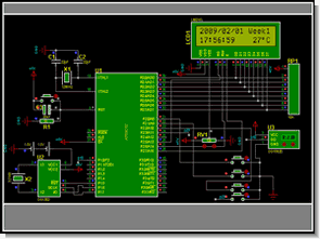
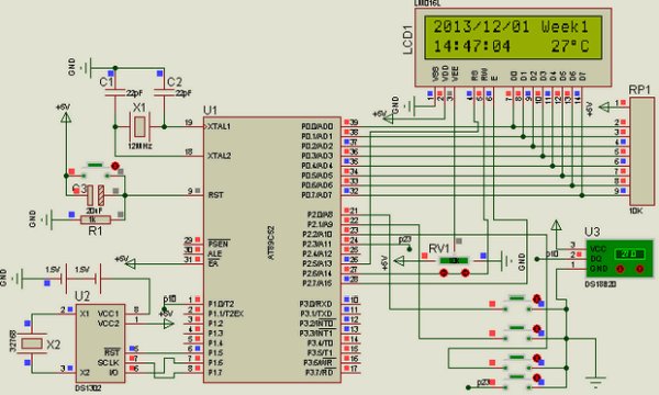
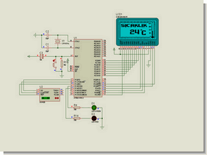
Soldering is probably the most difficult part of the project, as the keylogger hardware should be made as small as possible. The keylogger hardware schematics below show how connections should be made between components.

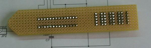
Solder the components together starting from the microcontroller and the EEPROM. Unused IC pins can be removed. Make sure the push button is accessible. When mounting the capacitor, make sure it’s biased correctly.

keylogger circuit 
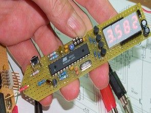
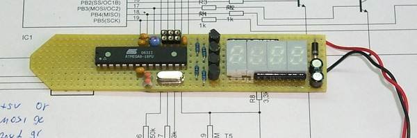
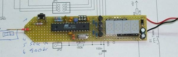
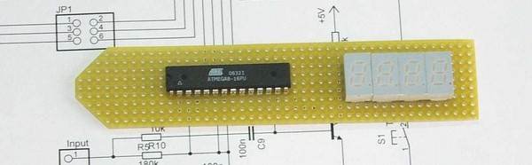
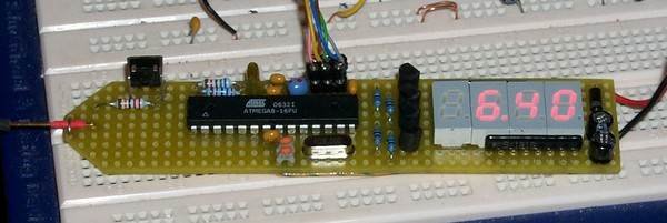
Make the hardware keylogger as compact as possible, however avoid short circuits. They will be difficult to remove after the device is finished. The keylogger circuit should look somewhat like the prototype shown on the photo, after the main components are connected.
Finally, solder the PS/2 connectors to the keylogger. A good idea is to cut the PS/2 extension cable into two pieces and solder each part separately. Make sure you put the heat shrink tubing on one part of the cable. Connect all four used PS/2 pins (CLK, DATA, VCC, and GND) on both connectors (at the keyboard and at the computer). connectors to the keylogger

Before pulling the thermal tubing around the hardware keylogger, a good idea is to let some glue or resin in between the components, to make the device more rigid. Finally pull the thermal tubing on, heat it until it wraps around the soldered components, and cut out a small hole so the button is accessible.

ubing around hardware keylogger


Record mode

The hardware keylogger starts recording key data once plugged between the keyboard and the computer. The keylogger is completely transparent for computer operation and cannot be detected by software in record mode. All key data sent by the keyboard will be recorded to 64 kB hardware non-volatile EEPROM memory. Record mode is completely independent from the operating system installed on the computer.

Find the PS/2 connector at the computer. Find the PS/2 connector


Disconnect the keyboard. Disconnect the keyboard
Connect the hardware keylogger in place of the keyboard. Connect the hardware keylogger


Connect the keyboard to the keylogger. On computer power-up data will start recording. Connect the keyboard to keylogger

Playback mode

Once the hardware keylogger has recorded key data, it can be retrieved to any PC running Windows 9X/Me/XP/2000. The hardware keylogger does this by simulating keyboard keystrokes. The transmitted keystroke data is acquired by a the KeyGrab application. Once this data has been transmitted to the computer, it can be processed and analyzed. Follow the instructions for initiating data download.

Run the KeyGrab application. Run the KeyGrab application


Connect the hardware keylogger instead of the keyboard. Do not connect the keyboard. Connect the hardware keylogger
Click on the KeyGrab title bar to make it the active application. Click on the KeyGrab title bar
Press the button on the hardware keylogger to initiate data download. Do not change the active application during transmission. Press the button again to finish transmission. Do this when the desired keystroke data has been downloaded to the PC.  Press the button on the hardware keylogger
Disconnect the hardware keylogger and plug your PS/2 keyboard back in. Disconnect the hardware keylogger

Data analysis

When downloading keystroke data to the KeyGrab main table, it’s automatically preprocessed to show key data that logged during recording. Data is transmitted in descending order, to show keys pressed recently first. Keystrokes that occurred a long time ago are transmitted later. You can analyze the table manually, or use some of the search options.

Data analysis

1     Position in keylogger hardware memory used by keyboard event (hex form).
2     Captured and logged keystroke.
3     Event that took place – a key press or release.
4     Keystroke scancode on PS/2 bus (hex form).
5     Last memory position written during recording (hex form).
6     Keylogger hardware memory size (in kilobits).

The only column that is of any interest to the user is Key (2) and Action (3). These columns code what keys have been pressed and released. Scroll the bar to see the keystroke history during recording. Keylogger data is transmitted in reverse chronological order (recent keystroke data first).


Download

The DIY hardware keylogger data retrieve and analysis application for Windows 9X/ME/2000/XP:

KeyGrab.zip (0.7MB)

The full source code for the AT89C2051 microcontroller:

Source code – diy.asm

The precompiled AT89C2051 hardware keylogger firmware is also available:

BIN file – diy.bin
HEX file – diy.hex

download


Source : keelog.com/diy.html PS2 Keyboard Keylogger Circuit Atmel AT89C2051 schematic source code files alternative link: ps2-keyboard-keylogger-circuit-atmel-at89c2051.rar alternative link2alternative link3

8051 MICROCONTROLLER UP DOWN COUNTER CIRCUIT (KEIL)

$
0
0

With 8051 DOWN COUNTER The basic principle of this circuit based on the number entered from the keypad is left counting down or up. # On the keypad to make counting down and counting… Electronics Projects,8051 Microcontroller Up Down Counter Circuit (keil) “8051 example, avr project, keil example, microcontroller projects, “

MICROCONTROLLER UP DOWN COUNTER CIRCUIT

With 8051 DOWN COUNTER The basic principle of this circuit based on the number entered from the keypad is left counting down or up. # On the keypad to make counting down and counting up pressing the * must be pressed to do.

8051 issues must be considered when programming the keypad is detected, the TIMER is used correctly.

8051 UP DOWN COUNTER SCHEMATIC

8051 UP DOWN COUNTER SCHEMATIC

Up Down Counter Circuit 8051 keil soruce code 8051 proteus isis schematic files: 8051-microcontroller-up-down-counter-circuit.rar author: Erkan ÇAĞLAR

Alternative File Download LINK list (in TXT format): LINKS-5453.zip


LCD DATE TIME TEMPERATURE AT89C52 DS18B20 DS1302

$
0
0

Atmel microcontrollers with a good example for the use of DS18B20 DS1302 circuit 2 × 16 LCD display with 4 buttons in circuit adjustments can be made The first button is a long hold… Electronics Projects, LCD Date Time Temperature AT89C52 DS18B20 DS1302 “8051 example, avr project, keil example, microcontroller projects, “

LCD DATE TIME TEMPERATURE

Atmel microcontrollers with a good example for the use of DS18B20 DS1302 circuit 2 × 16 LCD display with 4 buttons in circuit adjustments can be made

The first button is a long hold in seconds (h) setting switches to the second and third button with the settings is done after the first operation are repeating minutes goes like this continue operations after the last button and holding the set is being stored Retrieving AT89C52 system 12MHz frequency works

AT89C52 TEMPERATURE METER PROJECT

AT89C52 TEMPERATURE METER PROJECT

Temperature AT89C52 keil source code proteus isis simulation schematic files download: lcd-date-time-temperature-at89c52-ds18b20-ds1302.rar


AT89S52 DS1620 THERMOMETER CIRCUIT (LCD DISPLAY)

$
0
0

This project gave ds1620’n given as a result of the digitally using AT89S52 microcontroller is a graphic display of temperature information of the LCD screen. Moreover, the circuit ambient temperature when it reaches a…Electronics Projects, AT89S52 DS1620 Thermometer Circuit (LCD Display) “8051 example, avr project, keil example, microcontroller projects, “

THERMOMETER CIRCUIT

This project gave ds1620’n given as a result of the digitally using AT89S52 microcontroller is a graphic display of temperature information of the LCD screen.

Moreover, the circuit ambient temperature when it reaches a temperature above 250C is no longer a red LED lighting in the same way as the ambient temperature drops below 250C, a green LED lights up to notify user intended. 12 MHz crystal clock oscillator circuit to set the clock oscillator is used.

DS1620 is a temperature sensor and also the legs 8 is used as thermostat. Temperature is given as 9-bit data.

Demonstration of circuit temperature is obtained by using a 128 × 64 graphic LCD. LCD’s D0, D1, D2, D3, D4, D5, D6, D7 is provided with a connection to microcontrollers. Second intervals in the program I set the LCD also seems my school ID.

THERMOMETER CIRCUIT SCHEMATIC

THERMOMETER CIRCUIT SCHEMATIC

AT89S52 DS1620 Thermometer Circuit keil source: https://320volt.com/en/ds1620-at89s52-isi-olcumu-glcd-termometre/ code and proteus isis simulation schematic files:at89s52-ds1620-thermometer-circuit-lcd-display.rar Prepared by: @Sükriye KAYA Thanks to the People

Alternative File Download LINK list (in TXT format): LINKS-4761.zip

89C51 DIGITAL CLOCK CIRCUIT

$
0
0

From the incoming data encoded in Port0 integrated 7-segment display with 7447 microcontroller integrated ulaşır.7447 binary code from the 7-segment display is used to show. So when it comes to 0000 a, b, c,…Electronics Projects, 89C51 Digital Clock Circuit “8051 example, avr project, keil example, microcontroller projects, “

DIGITAL CLOCK CIRCUIT

From the incoming data encoded in Port0 integrated 7-segment display with 7447 microcontroller integrated ulaşır.7447 binary code from the 7-segment display is used to show.

So when it comes to 0000 a, b, c, d, e, f, g edu yanmaz.7 segment display LED lights bağlanmıştır.paralel parallel to each other using the same bus to the 7-segment display 7 segment display by selecting different at different times that instant If you have selected to display the data which goes to him.

In practice, common anode 7-segment display is used. Port 2 is connected to the terminals of transistors oval. Transistors display the benefits of riding. that is used to select one of a display. With the help of a single button port3 hour, minute, alarm settings are made.

Port1.0 a alarm fitted. One end of the button being available to the microcontroller used in the other end of the earthing. If the button is not pressed resistance feature is to send a signal to the microcontroller 1. So the trigger button enabled microcontrollers with 0.

89C51 DIGITAL CLOCK SCHEMATIC DIAGRAM

DIGITAL CLOCK SCHEMATIC DIAGRAM (1) DIGITAL CLOCK SCHEMATIC DIAGRAM (2)

89C51 Digital Clock Circuit keil source:https://320volt.com/en/89c51-7-segment-display-kullanarak-sayisal-saat/

code and proteus isis simulation schematic files: 89c51-digital-clock-circuit.rar author: @Neşe Horasan

Alternative File Download LINK list (in TXT format): LINKS-4750.zip

DS1302 RTC 8051 DIGITAL CLOCK CIRCUIT (LCD DISPLAY)

$
0
0

8051 keil example application circuit LCD Display Digital Clock using DS1302 RTC 8051 Digital Clock Schematic 8051 Digital Clock Circuit keil source code and proteus isis simulation schematic files: ds1302-rtc-8051-digital-clock-circuit-lcd-display.rar author: @Aytan ASLAN… Electronics Projects, DS1302 RTC 8051 Digital Clock Circuit (LCD Display) “8051 example, avr project, keil example, microcontroller projects, “

DIGITAL CLOCK CIRCUIT (1)

8051 keil example application circuit LCD Display Digital Clock using DS1302 RTC

8051 DIGITAL CLOCK SCHEMATIC

DIGITAL CLOCK SCHEMATIC

8051 Digital Clock Circuit keil source: https://320volt.com/en/8051-rtc-ds1302-ile-lcd-gosterimli-dijital-saat/ code and proteus isis simulation schematic files: ds1302-rtc-8051-digital-clock-circuit-lcd-display.rar author: @Aytan ASLAN

Alternative File Download LINK list (in TXT format): LINKS-4652.zip

8051 PROGRAMMABLE POWER SUPPLY

$
0
0

Circuit Operation: Circuit diagram appears in the 0-5 the entered value from the keypad circuit, which is connected to port P1 applied to the integrated DAC 0808 DAC output is obtained from the analog…Electronics Projects, 8051 Programmable Power Supply “8051 example, avr project, keil example, microcontroller projects, “

PROGRAMMABLE POWER SUPPLY

Circuit Operation: Circuit diagram appears in the 0-5 the entered value from the keypad circuit, which is connected to port P1 applied to the integrated DAC 0808 DAC output is obtained from the analog voltage. P0 port is connected to the 7-segment display of the absolute value of the voltage, which is connected to port P2 indicator shows the decimal value of the voltage. On the keypad “*” key to delete the entered value, “#” key, the entered value is used to convert the analog voltage. Output of 0-5 V 0.1 V-0, 2Volt precision analog voltage is obtained.

PROGRAMMABLE POWER SUPPLY CIRCUIT DIAGRAM

PROGRAMMABLE POWER SUPPLY CIRCUIT DIAGRAM (1) PROGRAMMABLE POWER SUPPLY CIRCUIT DIAGRAM (2)

8051 Programmable Power Supply Keil source: https://320volt.com/en/8051-ile-programlanabilir-guc-kaynagi-yapimi/ code proteus pcb simulation files: 8051-programmable-power-supply.rar AUTHOR: @Ali İhsan UYSAL

Alternative File Download LINK list (in TXT format): LINKS-4634.zip

ATMEL ATMEGA8 MULTIMETER CIRCUIT (LED DISPLAY)

$
0
0

Hello, “Multimeter” was the only title that first came to my mind to. Voltmeter (positive DC voltage) from 0.00 to 9.99 V and 10.0 – 30.0 V with automatic range switching. Frequency counter 0… Electronics Projects,Atmel Atmega8 Multimeter Circuit (led display) “atmega8 projects, avr project, microcontroller projects, “

MULTIMETER CIRCUIT

Hello, “Multimeter” was the only title that first came to my mind to. Voltmeter (positive DC voltage) from 0.00 to 9.99 V and 10.0 – 30.0 V with automatic range switching. Frequency counter 0 .. 7.999 MHz (theoretisch. ..) with automatic Change the time base

Logic tester L – Prohibited area – H (actually open line). The hardware is intentionally minimalist, the measurement accuracy miserable, voltage about 2%, frequency about 0.1%. Voltage is applied to unfavorable resistance values , at a frequency slightly ungünsitgen Counter-handling.

MULTIMETER CIRCUIT LED DISPLAY (1) MULTIMETER CIRCUIT LED DISPLAY (2) MULTIMETER CIRCUIT LED DISPLAY (3) MULTIMETER CIRCUIT LED DISPLAY (4) MULTIMETER CIRCUIT LED DISPLAY (5) MULTIMETER CIRCUIT LED DISPLAY (6)

Source: https://320volt.com/en/atmel-atmega8-16pu-ile-multimetre/ Atmel Atmega8 AVR Multimeter Circuit schematic AVR Studio source code files alternative link: atmel-atmega8-multimeter-circuit-led-display.rar alternative link2

Alternative File Download LINK list (in TXT format): LINKS-4403.zip

Viewing all 1082 articles
Browse latest View live