Introduction
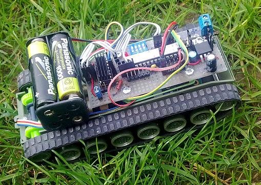
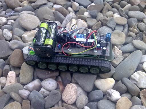
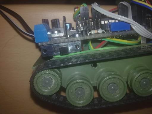
After two more complex robots ( Eurobot2008 and Robot2 ), I decided to build a small and simple car. The choice fell on a plastic tune, which was controlled by two AA pencil monoculars – similar toys can be found in toy shops, on soils or in bazaars. Others are available on the Internet (for example, Snailinstruments.cz has several of them – the chassis does not necessarily have to be belt-based, just two drive wheels and one swivel). The belt (differential) chassis is for a small robot, for example, because it can rotate in place. The robot can be controlled by a mobile phone via Bluetooth using OEMSPA310 .
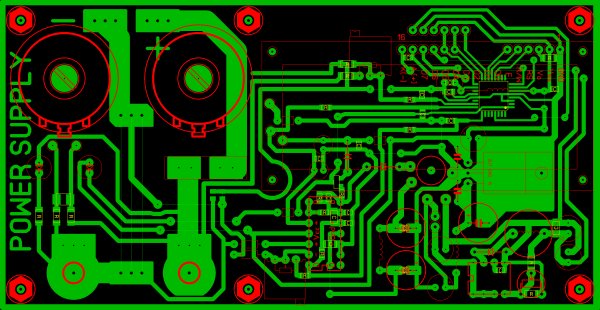
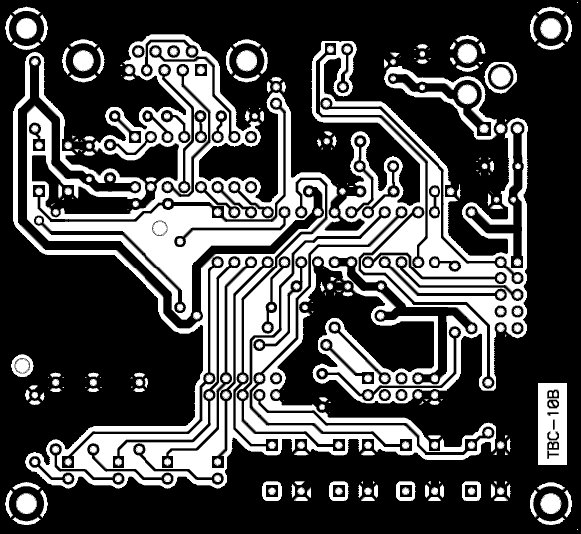
Plate
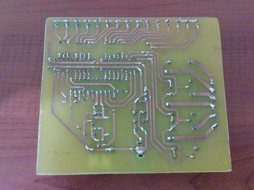
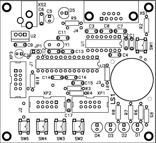
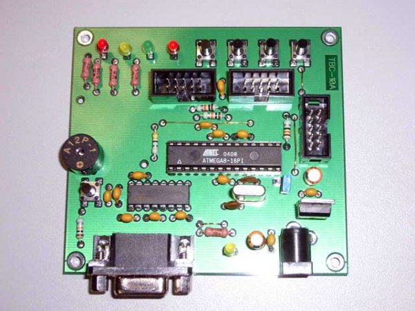
As the brain of the vehicle I used my favorite ATmega48 microcontroller – it is relatively inexpensive and has plenty of peripherals. The printed circuit board has a minimum wire jumpers and is designed to be built on a universal PCB with 2.54 mm grids that can be bought normally (I work with it by connecting the pads to the tin paths – it just wants a bit but the programmer can do it too ![]() ), but I have prepared a version that you can make at home with a photo. The holes are designed for M3 screws and M3 spacers and are positioned to fit into the Mercury kit (multiples of 10 mm). In addition to the ATmega48 single chip, the following parts are included:
), but I have prepared a version that you can make at home with a photo. The holes are designed for M3 screws and M3 spacers and are positioned to fit into the Mercury kit (multiples of 10 mm). In addition to the ATmega48 single chip, the following parts are included:
-
Stabilizer 7805 – stabilizes the 5 V supply voltage for the board.
-
Reset Button – When pressed, the program in the processor starts from the beginning.
-
Red LED connected to single pin (pin PD7).
-
DIP switch (4-bit switch) – it can be used, for example, to set program parameters (optional)
-
Ribbons for pinning all important single pin pins – wired as PIN | GND or PIN | 5V | GND to connect analog sensors or modellers (C single port).
-
H-bridge L293D for switching of two motors – max. 0.5 A (allows to change direction and control by means of pulse-width modulation – PWM). It is warmed up enough for bigger streams, it is good to add it to the heat of the soul (heatsink for DIP16 – for example in GM it is crowned). Then, just stick it with a second adhesive. It is good to note beforehand where the pin # 1 is located on the perimeter – the classic slot is covered by the cooler.
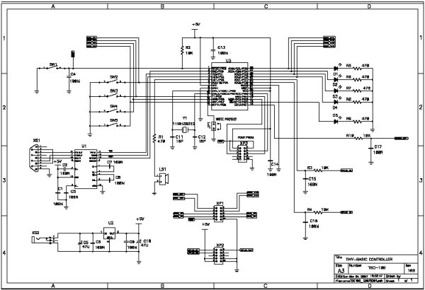
You can download Eagle files here . Pressing the Ratsnest Eagle button renders the rolled copper (GND) under the H-bridge, which helps the IC to smooth down.

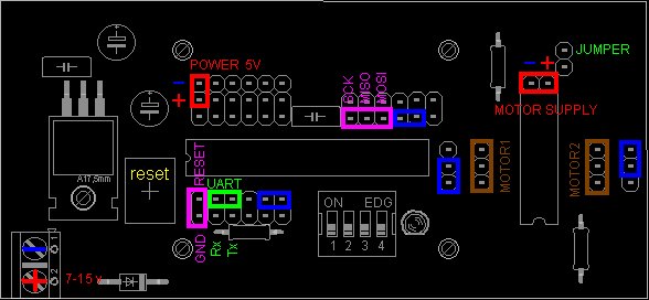
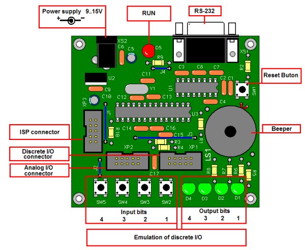
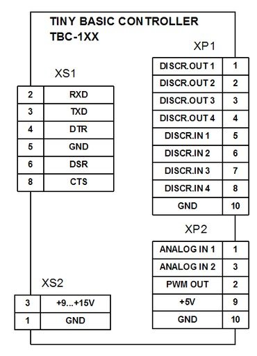
Connector Description
-
if the JUMPER is short-circuited, the motors are powered by 5V directly from the board. If not, it is powered from the MOTOR SUPPLY connector.
-
the UART connector is used to output a TTL-level serial channel, such as a Bluetooth module.
-
the POWER plug can be used to power the 5 V board directly or to power the peripherals (sensors, Bluetooth module) – be careful of polarity!
-
the MOTOR1 and MOTOR2 connectors are used to connect motors, the center pin (GND) can be fed to the motor frame if an interference is required.
-
the blue connectors on the H-bridge and the single-chip are interconnected by two-wire cables – they are used to control the motors and can be easily swapped or rotated.
-
Purple connectors indicate how to connect the programmer.
-
The yellow reset button is used to reset the program in a single chip.
-
The terminal block in the lower left corner serves to bring the unstable 7-15 V power to the board.
Kablíky
You need to prepare the following wires:
-
2x single-chip and h-bridge interconnect cable – dual (or triple if you want to change the pin enable h-mote for some reason)
-
connecting cable h-bridge-motors – on one side soldered to motors, on the other side PIN A | GND | PIN B. Pins A and B are connected to the motor terminals, the GND pin may remain loose or can be applied to the metal frame of the motor if you want to use the interference.
For production, the cable itself (for example, gray ten-pin), sockets, plastic packaging and pliers – all can be bought in GM under the name KONPC. It is good to buy them in stock. If you do not have a crimping pliers, I recommend this article , which describes the production nicely – do not try to solder them.
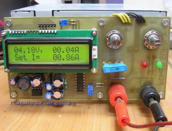
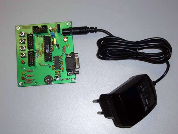
Power supply
With a 7805 stabilizer (replaceable with a lowdrop version), the board can be powered by 7-15 V, for example a classic 9 V battery or a 12 V drive from the old router. Although the power supply to the stabilizer is protected by a diode, it is good to note on the terminal board where the positive voltage is connected. It is good to place a small switch on the supply cable to the terminal board.
The whole board can be powered by four pencil monoculars, the voltage must be applied to one of the connectors (preferably on a three-row pin on port C) – here you have to pay attention to the polarity, the direct diode voltage is not protected by the five volts.
The board is the only jumper to set the power supply to the motors. if plugged in, the motors are powered by a 5-volt power supply when disconnected, they take power from their power connector. The jumper must not be plugged in if a larger voltage than 5 V is applied to the motor power connector – it will destroy the electronics .
For example, the switch can be glued directly below the board by, for example,
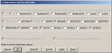
Single-chip programming
If you are in the one-chip area of the novice, I recommend to visit the page. We flash an LED that explains what a single chip is, how it works and how to program it using a simple programmer into a parallel port that consists of several resistors and a piece of cable. You can mount the individual wire pins (with a total of five) with the plugs described above separately or merge them into two connectors: RESET | GND and MOSI | MISO | SCK .
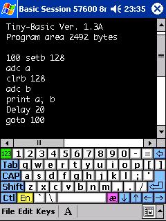
ATmega48 has an internal oscillator set to 8 MHz , so nothing needs to be set (canceling the 8-bit divider is solved in the program) and just load the hex file. It can be downloaded here withcomplete source code in C language (AVR-LIBC).
List of parts
-
IO ATmega48 + patice28 (just classic, not necessarily precise)
-
IO L293D (letter D is important – circuit contains protection diodes) + DIP16 socket (classical only, need not be precise) + optional cooler on DIP16, if it overheats
-
IO 7805 (P) (NE version L – has too little current) + optional cooler on TO220 if too heated
-
4-bit DIP switch (optional)
-
Microswitch (tact-switch)
-
PCB Terminals (2 pins)
-
Single-row and double-row straight flanged pegs (ridges)
-
LED red, 3 mm
-
Diode 1N4007
-
R 330 ohms
-
R 1k5 – 2x
-
C 2.2 uF (electrolyte)
-
C 100 uF (electrolyte)
-
C 0.1 uF – 2x (ceramics)
-
Jumper jumper
-
Cables, connectors and connectors
-
M3 screws, spacers, …
Source : goo.gl/O3gL Bluetooth Robot Project Alternative link: tank-robot-atmega48-bluetooth-java-project.rar


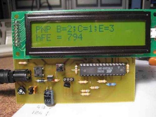
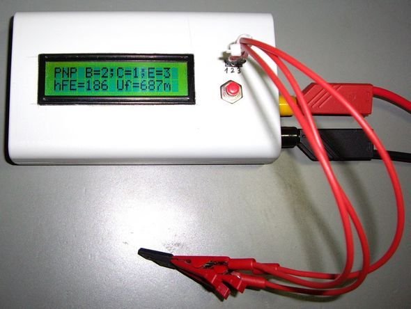
 Transistor test circuit, BJT, MOSFET, triac,…Electronics Projects, Transistor Tester Circuit ATMega8 LCD Display “atmega8 projects, avr project, microcontroller projects, “