Quantcast
Channel: AVR ATmega Projects Archives - Projects Tutorials Code Library for Atmels Atmega32 AVR
Viewing all 1082 articles
Browse latest View live

ATMEGA8 MOTORCYCLE ALARM CIRCUIT

$
0
0

Separate power supply. Signalling on mobile phone call.This function has only a few hundred euros more expensive equipment. motorcycle into the phone by calling The digital alarm input is a normally closed contact. The… Electronics Projects, ATmega8 Motorcycle alarm circuit “atmega8 projects, avr project, microcontroller projects, “

MOTORCYCLE ALARM CIRCUIT
Separate power supply. Signalling on mobile phone call.This function has only a few hundred euros more expensive equipment.
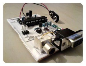
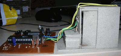
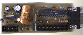
motorcycle into the phone by calling The digital alarm input is a normally closed contact. The analog input is deactivated when a certain resistance to +12 V is. It reacts to interruption and short-circuiting. Several alarm contacts can be connected in series. Help with mounting problems of the kind colleagues in the Honda Bol d’Or Board 🙂
ALARM CIRCUIT

Source: ATMEGA8 MOTORCYCLE ALARM CIRCUIT Motorcycle alarm circuit alternative link: atmega8-p-ile-motosiklet-alarm.rar alternative link2 alternative link3

Alternative File Download LINK list (in TXT format): LINKS-2664.zip


ATMEGA128 MMC CARD SUPPORTED 3-COLORS LED SIGN MESSAGE BOARD

$
0
0

ATmega128 microcontroller based on the ATmega128 a quality marquee project instead of text information stored on the MMC card codes shared resources At the beginning this project was to buy a led sign to...Electronics Projects, ATmega128 MMC Card Supported 3-Colors LED Sign Message Board “avr project, microcontroller projects, “

3-COLORS LED SIGN MESSAGE BOARD

ATmega128 microcontroller based on the ATmega128 a quality marquee project instead of text information stored on the MMC card codes shared resources

At the beginning this project was to buy a led sign to interface with my home automation network. This automation network display information like temperature wind speed, humidity etc I had bought on LED Sign but when I received it I got a surprise! There was no serial port to program messages

3 Colors messages
5 Scrolling speed
Serial port for uploading messages

LED SIGN PROJECT

LED SIGN PROJECT (1)

LED SIGN PROJECT (2)

LED SIGN PROJECT (3)

Source:ATMEGA128 MMC CARD SUPPORTED 3-COLORS LED SIGN MESSAGE BOARD alternative link: atmega128-mmc-card-supported-3-colors-led-sign-message-board.rar

ATMEGA32 10A 2-CHANNEL METER WITH LCD DISPLAY

$
0
0

10 Ampere circuit Ampere meter based on ATmega32 128×64 large LCD display it measures 10 amps in 2 channel AC DC used sed1330 Automatically Detect This project is a 2 channels amp meter. Those…Electronics Projects, ATmega32 10A 2-channel meter with LCD display “avr project, microcontroller projects, “

10A 2-CHANNEL METER

10 Ampere circuit Ampere meter based on ATmega32 128×64 large LCD display it measures 10 amps in 2 channel AC DC used sed1330 Automatically Detect

This project is a 2 channels amp meter. Those channels are completely isolated up to 2000 volts. I’m sure you don’t need isolation like this but it could be very interesting to measure the charge current for 110V AC input or on the output of something like 12V DC. That is, it provides auto detection for AC or DC current. The main part of this project is the current sensor ZMC10 a cool DIP 14, which supports up to 10 A. The current is measured inside by hall effect sensor. I had used a graphic LCD to show very big numbers of the read current and max peek value, DC or AC

2 Channel
From 0 to 10amp
Resolution of 0.1amp
Isolation between each channel of 2000 volt
Automatic AD/DC detection
Very big LCD and character

10A 2-CHANNEL METER WITH LCD DISPLAY(1) 10A 2-CHANNEL METER WITH LCD DISPLAY(2) 10A 2-CHANNEL METER WITH LCD DISPLAY(3) 10A 2-CHANNEL METER WITH LCD DISPLAY(4) 10A 2-CHANNEL METER WITH LCD DISPLAY(5)

Source: ATMEGA32 10A 2-CHANNEL METER WITH LCD DISPLAY alternative link: 10A 2-channel meter.rar

Alternative File Download LINK list (in TXT format): LINKS-2660.zip

ATMEGA32 10A 2-CHANNEL METER WITH LCD DISPLAY

$
0
0


PID Temperature Controller Max232 PC via RS232 serial port connection can be made According to information I found PID Temperature Controller is accurate temperature control system i AT90S2313 control system with high mains voltage… Electronics Projects, AT90S2313 Computer Supported PID Temperature Controller “avr project, microcontroller projects, “

PID TEMPERATURE CONTROLLER

PID Temperature Controller Max232 PC via RS232 serial port connection can be made According to information I found PID Temperature Controller is accurate temperature control system i AT90S2313 control system with high mains voltage MOC3061 Opto-isolated TRIAC BTA10-600B used for AC Control

PID TEMPERATURE CONTROLLER

What’s a PID controller? PID stands for “proportional integral differential” and relates to a process which seeks to continuously correct the error between a measured variable and a desired setting by calculating an appropriate correction process. In practice, it can largely avoid the large overshoots and undershoots that occur in simple temerature control systems.

PID TEMPERATURE CONTROL PROJECT

PID TEMPERATURE CONTROL PROJECT (1)

PID TEMPERATURE CONTROL PROJECT (2)

Source:AT90S2313 COMPUTER SUPPORTED PID TEMPERATURE CONTROLLERPID Temperature Control schematic pcb sowtware AT90S2313 source code alternative link:at90s2313-computer-supported-pid-temperature-controller.rar alternative link2

8051 PS2 KEYBOARD WITH LCD WRITING TEXT

$
0
0

PS / 2 protocol used text via a keyboard microcontroller applications that perform printing text on the LCD The goal here Text via keyboard microcontroller to print text on the LCD. Through keyboard microcontroller…Electronics Projects, 8051 PS2 Keyboard with LCD Writing Text “8051 example, avr project, keil example, microcontroller projects, “

8051 PS2 KEYBOARD

PS / 2 protocol used text via a keyboard microcontroller applications that perform printing text on the LCD

The goal here Text via keyboard microcontroller to print text on the LCD. Through keyboard microcontroller contained in a code corresponding to each keystroke is generated. About scan code ASCII code is used as code corresponds microcontroller and LCD is switched to the found and processed. Circuit connectors are shown below:

8051 PS2 KEYBOARD CIRCUIT DIAGRAM

Analyzing Source code “t_lcd.h” and tarama.h named header files have been used. Contains functions that are required to drive LCD “t_lcd.h” header file is given below. “Tarama.h” header file for the PS / 2 keyboard scan codes corresponding to each of the keys are included.

Keil and proteus isis ares files to the 8051 PS2 Keyboard project: 8051-ps2-keyboard-with-lcd-writing-text.rar  Source : 8051 PS2 KEYBOARD WITH LCD WRITING TEXT

AT89C51 ANIMATED BMP GRAPHIC LCD DISPLAY

$
0
0

AT89C51 microcontroller controlled Animated BMP project usnig Graphic LCD Display 128×64 project keil source code and proteus isis simulation schematic files Graphic LCD Animated BMP Schematic project files: at89c51-animated-bmp-graphic-lcd-display.rar author: Cihangir Kılıç… Electronics Projects, AT89C51 Animated BMP Graphic LCD Display “8051 example, avr project, keil example, microcontroller projects, “

GRAPHIC LCD DISPLAY

AT89C51 microcontroller controlled Animated BMP project usnig Graphic LCD Display 128×64 project keil source code and proteus isis simulation schematic files

GRAPHIC LCD ANIMATED BMP SCHEMATIC

GRAPHIC LCD ANIMATED BMP SCHEMATIC

Source : AT89C51 ANIMATED BMP GRAPHIC LCD DISPLAY project files: at89c51-animated-bmp-graphic-lcd-display.rar author: Cihangir Kılıç

AT89C51 MICROCONTROLLER ANALOG CLOCK FOR GRAPHIC LCD

$
0
0

Analog Clock GLCD We use 128×64 pixel graphical LCD having “HY-12864K” is. This adds the file extension of the LCD connections are provided in PDF. 128 × 64 graphic LCD s have the same… Electronics Projects,AT89C51 Microcontroller Analog Clock for Graphic LCD “8051 example, avr project, keil example, microcontroller projects, “

ANALOG CLOCK FOR GRAPHIC LCD

Analog Clock GLCD We use 128×64 pixel graphical LCD having “HY-12864K” is. This adds the file extension of the LCD connections are provided in PDF. 128 × 64 graphic LCD s have the same general structure. Differences spending power connection types and LED colors. Graphic LCDs are managed as two frames (64 × 64) and consists of three parts. Rows, columns and pages. Page 8 of 128 × 64 graphic display as standard and has 64 columns.

ANALOG CLOCK CIRCUIT

ANALOG CLOCK CIRCUIT (1) ANALOG CLOCK CIRCUIT (2)

source: AT89C51 MICROCONTROLLER ANALOG CLOCK FOR GRAPHIC LCD Analog Clock circuit keil source code proteus isis simulation schematic files at89c51-microcontroller-analog-clock-for-graphic-lcd.zip

ATMEL ATMEGA8 IR DETECTOR CIRCUIT

$
0
0

8-channel approach to IR detector sensor circuit is realized with ATmega8 microcontroller. I2C bus (TWI, SMBus) are measuring through the obstacle detection, designed for mobile robot. Approach reflects the beam of infrared light detector… Electronics Projects, Atmel ATMEGA8 IR detector circuit “atmega8 projects, avr project, microcontroller projects, “

ATMEL ATMEGA8 IR DETECTOR CIRCUIT

8-channel approach to IR detector sensor circuit is realized with ATmega8 microcontroller. I2C bus (TWI, SMBus) are measuring through the obstacle detection, designed for mobile robot. Approach reflects the beam of infrared light detector circuit based on monitoring works.

8-CHANNEL DETECTION INFORMATION

Measuring principle: Infrared light reflection Detection
Max. Sensor: 8 independent sensor
Communication interface: I2C – 7bit address
Module size: 78 x 62 mm (3 “x 2.44”)
Measuring the number of degrees: 3 distance levels (Min, Mid, Max)
Supply voltage: +5 V (DC)
Current consumption: 15 mA
Microprocessor: ATMEGA8 ATMEL (AVR – 8MHz)

ATMEGA8 PROXIMITY DEDECTOR

ATMEGA8 PROXIMITY DEDECTOR (1)

The aim of this work was to design and implement hardware detector proximity and provide adequate control program, which will be carried out measurements and the results transmitted to the request nadrazenému Management System, through the I2C bus (TWI, SMThe module is designed for educational mobile robot, as detector barriers to the robot unknown environment. With help of a signal can be further processed such as neural networks.

ATMEGA8 PROXIMITY DEDECTOR (1)

Source: ir.babjak.cz/ IR detector circuit schematic Source2: ATMEL ATMEGA8 IR DETECTOR CIRCUIT  source code pcb files alternative link: atmel-atmega8-ir-sensor-detection-circuit.rar alternative link2 alternative link3


MONITOR TEST CIRCUIT WITH ATMEGA88

$
0
0

color image of a classic test circuit will monitor the audio output of this circuit in addition to the music in the game are from the old ateri amp could work in the test… Electronics Projects, Monitor Test Circuit with atmega88 “avr project, microcontroller projects, “

MONITOR TEST CIRCUIT

color image of a classic test circuit will monitor the audio output of this circuit in addition to the music in the game are from the old ateri amp could work in the test sample watch the video you’ll see 🙂

MONITOR TEST CIRCUIT WORK

MONITOR TEST CIRCUIT WORK (1) MONITOR TEST CIRCUIT WORK (2) MONITOR TEST CIRCUIT WORK (3) MONITOR TEST CIRCUIT WORK (4) MONITOR TEST CIRCUIT WORK (5) MONITOR TEST CIRCUIT WORK (6) MONITOR TEST CIRCUIT WORK (7) MONITOR TEST CIRCUIT WORK (8) MONITOR TEST CIRCUIT WORK (9)

Source: linusakesson.net Source2: MONITOR TEST CIRCUIT WITH ATMEGA88 Monitor Test Circuit with atmega88 alternative link: monitor-test-circuit-with-atmega88.rar

DISEQC TESTER CIRCUIT WITH ATMEL ATTINY13

$
0
0

This device is designed to help define the way DiSEqC-switches to the working protocols 1.0 and 1.1 and the number of entrances to 4 – x. It feeds the unit from the source of… Electronics Projects, DiSEqC Tester Circuit with Atmel ATtiny13 “avr project, microcontroller projects, “

DISEQC TESTER CIRCUIT

This device is designed to help define the way DiSEqC-switches to the working protocols 1.0 and 1.1 and the number of entrances to 4 – x. It feeds the unit from the source of constant tension 12 V. For monitoring of correct inputs diseka used LEDs, which, if correct diseka must times a second switch, with only one to shine lights at any time. Permanent luminescence or nesvechenie one of the LED will indicate the failure sign. Moreover, it is possible to reduce the amplitude of parcels 22 kHz to 300 mV to test our diseka in difficult circumstances, such as long feeder.

DISEQC TESTER CIRCUIT (1)

Power supply – 12 V, a maximum of 200 mA
The number of controlled ports – 4, with the help of embedded LEDs
Protocol support DiSEqC 1.0, DiSEqC 1.1 (Write Port Group Commands)
2 22kHz-tone levels – 650mV, 300mV
The frequency of issuing commands – 1 Hz, 2 Hz, switch ports in a circle
Light and sound transmission indication commands
Protection against short circuits (current limit) with light and audible warning

DISEQC TESTER CIRCUIT (2)

Source: DISEQC TESTER CIRCUIT WITH ATMEL ATTINY13 DiSEqC Tester Circuit with Atmel ATtiny13 schematic hex code alternative link: diseqc-tester-circuit-with-atmel-attiny13.rar

AT89C51 SQUARE WAVE SIGNAL GENERATOR

$
0
0

Signal generator test is often the recipients of the amplifiers used in the test and repair of this equipment. Used as the signal source. Wave detector, radio frequency used in places such as bridges…. Electronics Projects, AT89C51 Square Wave Signal Generator “8051 example, avr project, keil example, microcontroller projects, “

SQUARE WAVE SIGNAL GENERATOR

Signal generator test is often the recipients of the amplifiers used in the test and repair of this equipment. Used as the signal source. Wave detector, radio frequency used in places such as bridges. Integrated signal generator, the steady operation, because of the cost is low and it is preferable to be mixed. Attractions signal generator used in the experiments 1Hz – 10Hz and 100Hz frequency will produce. When prompted, the program used can be obtained by varying the maximum 500MHz square wave signal.

Source : AT89C51 SQUARE WAVE SIGNAL GENERATOR AT89C51 Square Wave Signal Generator pcb schematic keil source code at89c51-square-wave-signal-generator

AT89C51 L293D DC MOTOR WITH DOOR CONTROL CIRCUIT

$
0
0

The main purpose of the circuit is to control the gate of the house. This DC motor and provided with two limit switches is provided by mechanical parts. The two buttons open and close… Electronics Projects, AT89C51 L293D DC Motor with Door Control Circuit “8051 example, avr project, keil example, microcontroller projects, “

DC MOTOR WITH DOOR CONTROL CIRCUIT

The main purpose of the circuit is to control the gate of the house. This DC motor and provided with two limit switches is provided by mechanical parts. The two buttons open and close the circuit inside is available. Sent to the ends of the drive motor integrated into 1 and 0 knowledge engine is turning left or right.

AT89C51RD2 switches are connected in series to the output port. As soon as the door closed one of the key information by sending port is disconnected. When the other button is pressed, this time the information is sent to one of the other ports and the engine returns to the other side and this time it is connected to the switch port opens.

L293D DC MOTOR DOOR CONTROL

L293D DC MOTOR DOOR CONTROL(1) L293D DC MOTOR DOOR CONTROL(2) L293D DC MOTOR DOOR CONTROL(3)

L293D DC MOTOR DOOR CONTROL SCHEMATIC PCB

L293D DC MOTOR DOOR CONTROL SCHEMATIC PCB (1) L293D DC MOTOR DOOR CONTROL SCHEMATIC PCB (2)

L293D PIN CONNECTING

L293D PIN CONNECTING (1)

Output Ports Connection Diagram with Motor Drive

L293D PIN CONNECTING (2)

Source: DC MOTOR WITH DOOR CONTROL CIRCUIT AT89C51 L293D DC Motor with Door Control proteus isis schematic pcb keil source code at89c51-l293d-dc-motor-with-door-control.rar

AT89C51 8051 GRAPHIC LCD ANIMATION

$
0
0

GLCD Animation circuit voltage is applied to the currently displayed map of Turkey comes first. Subsequently, the Turkish flag and a picture of Mustafa Kemal Atatürk, the next step is to come. Art world… Electronics Projects, AT89C51 8051 Graphic LCD Animation “8051 example, avr project, keil example, microcontroller projects, “

GRAPHIC LCD ANIMATION

GLCD Animation circuit voltage is applied to the currently displayed map of Turkey comes first. Subsequently, the Turkish flag and a picture of Mustafa Kemal Atatürk, the next step is to come. Art world will begin to come after arrival.

GRAPHIC LCD ANIMATION(1)

Circuit operation: Graphic LCD as the most important feature point-based study. So, as in LCDs text and text can be printed as well as shape can be drawn. Half-P2 as data output port ayarlanmıştır.p1_0 end graphic LCD’s CS1, CS2 end P1_1 port is connected to the graphic LCD. Graphic Lcd structure is divided into 2 sections, including the right and left.

LCD ANIMATION SCHEMATIC

LCD ANIMATION SCHEMATIC

Source: AT89C51 8051 GRAPHIC LCD ANIMATION 8051 Graphic LCD Animation proteus isis simulation schematic keil source code8051-graphic-lcd-animation.rar author:Avni ÇiFTÇiLER

CALCULATION OF BODY LENGTH WITH 8051 AND DS89C430

$
0
0

In this project, which is designed using DALLAS DS89C430 microcontroller (in simulation AT89C51RC2) circuit and a marching band, calculated on the length of the body, the LCD display was performed. Circuit consists of three… Electronics Projects, Calculation of Body Length with 8051 and DS89C430 “8051 example, avr project, keil example, microcontroller projects, “

CALCULATION OF BODY LENGTH

In this project, which is designed using DALLAS DS89C430 microcontroller (in simulation AT89C51RC2) circuit and a marching band, calculated on the length of the body, the LCD display was performed.

Circuit consists of three parts.
In the first part, designed with the supply voltage for regulating the voltage source 7805 is used.

In the second part of the object on the moving walkway Fototransistörl sensor for detecting the sensor circuit can be used.

The third part of the circuit consists of a portion of the 8051 microcontroller and LCD.

CALCULATION OF BODY LENGTH(1)

DS89C430 PROGRAMMER CIRCUIT

DS89C430 PROGRAMMER CIRCUIT

DS89C430 PROGRAMMER CIRCUIT (1)

DS89C430 PROGRAMMER CIRCUIT (2)

DS89C430 PROGRAMMER CIRCUIT (3)

Source: CALCULATION OF BODY LENGTH Calculation of Body Length with 8051 and DS89C430 keil source code proteus isis simulation schematic calculation-of-body-length-with-8051-and-ds89c430.rar

89C51 8051 VOLTMETER THERMOMETER DS1621 ADC0808

$
0
0

ADC 0808 standard data acquisition systems many components on a single chip host is a member of ADC 0808 8-bit flip makes the process and addresses from input latch 8-channel data selection (multiplexer) and…Electronics Projects, 89C51 8051 voltmeter thermometer DS1621 ADC0808 “8051 example, avr project, keil example, microcontroller projects, “

VOLTMETER THERMOMETER

ADC 0808 standard data acquisition systems many components on a single chip host is a member of ADC 0808 8-bit flip makes the process and addresses from input latch 8-channel data selection (multiplexer) and microprocessor compatible with the associated control logic provides.

ADC 0808 standard data acquisition systems many components on a single chip host is a member of ADC 0808 8-bit flip makes the process and addresses from input latch 8-channel data selection (multiplexer) and microprocessor compatible with the associated control logic provides.

Source: 89C51 8051 VOLTMETER THERMOMETER DS1621 ADC0808 89C51 8051 voltmeter thermometer DS1621 ADC0808 Proteus isis simulation pcb keil source code 89c51-8051-voltmeter-thermometer-ds1621-adc0808.rar


AT89S52 8051 RF DC MOTOR SPEED CONTROL

$
0
0

Wireless within a certain area with a control circuit for controlling the speed of DC Motor. Work, should I use to reach my goal I began to identify materials. These materials AT89S52 microcontroller, our… Electronics Projects, AT89S52 8051 RF DC Motor Speed Control “8051 example, avr project, keil example, microcontroller projects, pwm circuits, “

DC MOTOR SPEED CONTROL

Wireless within a certain area with a control circuit for controlling the speed of DC Motor. Work, should I use to reach my goal I began to identify materials. These materials AT89S52 microcontroller, our independent auditor by the company manufactured and price is also suitable 433MHz UHF frequency band enables communication RF receiver and transmitter modules, (ATX-34 ARX-34) DC motor will L293B 4-channel push-pull driver IC circuit to feed the fixed were elements that will provide voltage LM7805 and the environment (condensers). Then these steps simulation, PCB drawings (drawings were made in Protel dxp2004) and watched the process of writing programs in Keil

RF DC MOTOR SPEED CONTROL AT89S52

RF DC MOTOR SPEED CONTROL AT89S52 (1) RF DC MOTOR SPEED CONTROL AT89S52

System operation: Control circuit and motor control circuits with RF module via serial port 8051 is a one-way communication. Increase or decrease the speed of the speed control circuit of any one of the buttons on the appropriate button is pressed, the cutting program is executed and motor control circuits based on the relevant button to increase the speed or decrease the speed commands are sent. This command area of the control system by evaluating them will increase or decrease the speed of the motor will decide. The engine speed PWM (Pulse Width Modulation) method to set the 8051 program was written. In the form of PWM voltage pulse is sent to the engine. Stay at one of these pulses in the period no matter how long the engine turns so fast. PWM control of the motor speed is generally done in this manner.

RF DC MOTOR SPEED CONTROL AT89S52(2) RF DC MOTOR SPEED CONTROL AT89S52(3)

Source: AT89S52 8051 RF DC MOTOR SPEED CONTROL AT89S52 8051 keil source code RF DC Motor Speed Control proteus isis simulation schematic pcb at89s52-8051-rf-dc-motor-speed-control.rar

ATMEGA128 ATMEGA32 PC CONTROLLED LED MATRIX ANIMATION LED SIGNS

$
0
0

Serve to control the 128×64 graphic LCD with a preview of the contents of the array and menu graphics. The heart of the controller is Atmega 128 CPU for communication with the PC corresponds… Electronics Projects, ATMEGA128 ATMEGA32 PC Controlled LED Matrix Animation LED Signs “avr project, microcontroller projects, “

LED MATRIX ANIMATION LED SIGNS

Serve to control the 128×64 graphic LCD with a preview of the contents of the array and menu graphics. The heart of the controller is Atmega 128 CPU for communication with the PC corresponds to the FTDI FT232BM. As today is the prototype implemented a very simple menu on the display + 3-button keypad. A fully functioning transmission to PC and oscilloscope generated in real time. On the photos you can see the prototype and actually his half (motherboard) and connected to the test display, in the future all will be on the plate interface.

The driver array is a device intermediary in the transmission of data from the computer to the array, but also allow her to work autonomously without a PC. It is a project that is constantly evolving. Basic features include:

LED SIGNS LED MATRIX ANIMATION TEST

– Transmission of PC => array via USB
– Supports SD / MMC card
– Visualization of real-time audio
– Text from the keyboard in real time
– Supports LAN
– Parallel port for different types of applications
– And who knows what else figure it out 😉

LED SIGNS LED MATRIX ANIMATION TEST (1) LED SIGNS LED MATRIX ANIMATION TEST (2) LED SIGNS LED MATRIX ANIMATION TEST (3) LED SIGNS LED MATRIX ANIMATION TEST (4) LED SIGNS LED MATRIX ANIMATION TEST (5) LED SIGNS LED MATRIX ANIMATION TEST (6)

Atmega32 microcontroller circuit boards control is provided via a computer loaded with animation effect can show writings PCB schematics and software files are

Source: PC CONTROLLED LED MATRIX ANIMATION LED SIGNS Computer Controlled LED Signs PCB source code schematic alternative link:atmega128-computer-controlled-led-matrix-animation-led-signs.rar alternative link2 alternative link3

USB TO LPT CONVERTER CIRCUIT WITH ATMEL ATMEGA8

$
0
0

Converter from USB to LPT parallel port (25 pin SubD receptacle) with hardware virtualization at input/output instruction level Supports all parallel port modes named SPP, EPP and ECP, 16 Byte FIFO depth USB Low… Electronics Projects, USB to LPT Converter Circuit with Atmel ATMEGA8 “atmega8 projects, avr project, microcontroller projects, “

USB TO LPT CONVERTER CIRCUIT

Converter from USB to LPT parallel port (25 pin SubD receptacle) with hardware virtualization at input/output instruction level Supports all parallel port modes named SPP, EPP and ECP, 16 Byte FIFO depth USB Low Speed (1.5 Mbit/s signaling; 1 kByte/s for input/output instructions) Supports USB suspend mode with reduced power consumption Full open-source, even for schematics and PCBs
In particular laptop works well with a circuit 🙂 USB port Lpt port çevriy Windows 98-Me-2k-XP-Vista driver files there is also the source. C. H. Hex code and eagle crafted with PCBs schema files are

USB TO LPT

USB TO LPT (1)

Source: USB TO LPT CONVERTER CIRCUIT USB to LPT Converter Circuit with Atmel ATMEGA8 alternative link: usb-to-lpt-converter-circuit-with-atmel-atmega8.rar alternative link2link3

WAV PLAYER CIRCUIT WITH ATMEL ATTINY2313

$
0
0

ATtiny2313 microcontroller circuit with MAX232 PC connection can be established based on the pc program with wav file loading the output of the power amplifier TDA2003 integrated amp Atmel Wav Player Circuit Test The… Electronics Projects, Wav Player Circuit with Atmel ATtiny2313 “avr project, microcontroller projects, “

WAV PLAYER CIRCUIT

ATtiny2313 microcontroller circuit with MAX232 PC connection can be established based on the pc program with wav file loading the output of the power amplifier TDA2003 integrated amp

ATMEL WAV PLAYER CIRCUIT TEST

ATMEL WAV PLAYER CIRCUIT TEST

The electronic circuit it ATtiny2313-mas* mikrovezérlo that of a circle is being built. AVR-hez* the memory IC (AT45DB4161) a voltage divider is attached with resistances since the memory is a maximum 3.6V-ot* is able to tolerate it. According to this Z-diódás with a stabilizer 3.3V-ra* the supply voltage is portrayed for IC. From IC it adatvzeték* the AVR re is attached directly since he is AVR the 3.3V-ot* H can perceive it as a level yet.

The digital code being equal to the sound AVR single R-2R turns it into an analogous sign with a network, mainly the cost effectiveness and I decided it because of the simplicity at this solution. The strengthening grade follows this. For strengthening IC TDA2003-mat* I singled it out mainly his plain connection, his price, and the equivalent, cca. 10W-os* because of his leave performance.

To put on a sound for the apparatus, to delete we are top notch with the help of a computer. The electronic circuit sorosporttal* is attached to the computer, this an MAX232 type next fitting accomplishes it through IC

Source: WAV PLAYER CIRCUIT Wav Player Circuit pcb aschematic source code Alternative link: wav-player-circuit-with-atmel-attiny2313.rar alternative link2 alternative link3 alternative link4

COMPUTER CONTROLLED 8-CHANNEL DIMMER CIRCUIT

$
0
0

AT90S2313P 200 watt dimmer circuit is controlled from RS232 port with MOC3021 opto isolated triac driver control program running on xp pretty simple hex to asm code pcb diagram AT90S2313P There have also dosyalarıda… Electronics Projects, Computer Controlled 8-Channel Dimmer Circuit 200W AT90S2313P”avr project, microcontroller projects, “

DIMMER CIRCUIT

AT90S2313P 200 watt dimmer circuit is controlled from RS232 port with MOC3021 opto isolated triac driver control program running on xp pretty simple hex to asm code pcb diagram AT90S2313P There have also dosyalarıda pc program source code. rs232dimmer.asm, rs232dimmer.hex, dimmer.vbp, dimmer.vbw, dimmer.frx

PC CONTROLLED DIMMER CIRCUIT

PC CONTROLLED DIMMER CIRCUIT

8 channel mains dimmer

The heart of the dimmer is a ATTiny2313. the AVR performs three tasks: – It receives new data via the com port, – He receives pulses and the power of positive to negative goes and vice versa, this is called the zero crossing. – He makes 8 pulse-width modulated signal (PWM) with a frequency of 100 Hz. these signals are equal to the zero crossings from the mains.

The PWM signals control 8 optotriacs. These are optocouplers but with a built-in low power triac which can switch. In this project be MOC3021 optocoupler used. You can also add other optotriacs use as long as they have no zero-crossing detection, because working not if you want dim.

8 channel mains dimmer (1) 8 channel mains dimmer (2)

source: COMPUTER CONTROLLED 8-CHANNEL DIMMER CIRCUIT Computer Controlled 8-Channel Dimmer Circuit pcb schematic avr source code pc program alternative link: computer-controlled-8-channel-dimmer-circuit-200w-at90s2313p.rar

Viewing all 1082 articles
Browse latest View live