Quantcast
Channel: AVR ATmega Projects Archives - Projects Tutorials Code Library for Atmels Atmega32 AVR
Viewing all 1082 articles
Browse latest View live

MODEL AIRCRAFT PROJECTS

$
0
0

Different models of the project Model Aircraft Model airplane models, drawings, model details, sample circuits, fan motors, etc. .. as well as stock control circuit microchip PIC16F microcontrollers made with a variety of serial… Electronics Projects, Model Aircraft Projects “avr project, microcontroller projects, “

MODEL AIRCRAFT

Different models of the project Model Aircraft Model airplane models, drawings, model details, sample circuits, fan motors, etc. .. as well as stock control circuit microchip PIC16F microcontrollers made with a variety of serial control, driver circuits have

I created the archive for quota shortage of people who collectively can download all model aircraft applications

Make, model work a deal okadarda an enjoyable challenging outlay usually costs a lot 🙂 I know from a friend: D though I guess it would deal with meket car is not much difference in air

EXAMPLES OF MODEL AIRCRAFT PROJECTS

EXAMPLES OF MODEL AIRCRAFT (1) EXAMPLES OF MODEL AIRCRAFT (2) EXAMPLES OF MODEL AIRCRAFT (3) EXAMPLES OF MODEL AIRCRAFT (4) EXAMPLES OF MODEL AIRCRAFT (5) EXAMPLES OF MODEL AIRCRAFT (6) EXAMPLES OF MODEL AIRCRAFT (7) EXAMPLES OF MODEL AIRCRAFT (8)

Source: MODEL AIRCRAFT PROJECTS Model Aircraft Projects files Model Aircraft Projects.rar alterntif link2 alternative link3


AT89S52 THERMISTOR CIRCUIT THERMOMETER LCD DISPLAY

$
0
0

NTC Thermistor Thermometer based on AT89S52 circuit and HIH 3160 humidity sensor humidity and temperature information is given. Display LCD display circuit and there are two versions of the C source code and schema… Electronics Projects, AT89S52 Thermistor Circuit Thermometer LCD Display “avr project, microcontroller projects, “

THERMOMETER LCD DISPLAY

NTC Thermistor Thermometer based on AT89S52 circuit and HIH 3160 humidity sensor humidity and temperature information is given. Display LCD display circuit and there are two versions of the C source code and schema files have been prepared by Orcad.

AT89S52 THERMISTOR CIRCUIT

Thermistor Thermometer: LCD version: The ADC and thermistor circuits are quite the same as the 1st version. The ADC can be LTC1298 or MCP3202. Now with this design, P0 is used to interface LCD bus. SW1 is optional key switch. Since the number of I/O port are not many, we then can replace the 40-pin MCU with 20-pin MCU easily. J2 is available for connecting another sensor. The input range is 0 to +5V. HIH-3160 Honeywell Relative Humidity Sensor

Source: AT89S52 THERMISTOR CIRCUIT THERMOMETER LCD DISPLAY Thermistor Thermometer LCD Display Alternative link: at89s52-thermistor-thermometer-lcd-display.rar

SPEED ​​INDICATOR CIRCUITS TACHOMETER ATMEL ATMEGA8

$
0
0

Atmel ATmega series of projects have been realized with the speedometer and LCD display are the different indicators used circuits. Display circuit used Used atmega8l-8P. Hex file and prepared by Proteus. Dns file there…. Electronics Projects, Speed Indicator Circuits Tachometer Atmel atmega8 “atmega8 projects, avr project, microcontroller projects, “

SPEED ​​INDICATOR CIRCUITS

Atmel ATmega series of projects have been realized with the speedometer and LCD display are the different indicators used circuits.

Display circuit used Used atmega8l-8P. Hex file and prepared by Proteus. Dns file there. The circuit has two different versions of LCD ATMega16 and used ATMEGA8515

SPEED ​​INDICATOR CIRCUITS(1) SPEED ​​INDICATOR CIRCUITS(2) SPEED ​​INDICATOR CIRCUITS(3)

Source: SPEED INDICATOR CIRCUITS Speed Indicator Circuits files: speed- indicator-circuits.rar alternative link2

ATMEGA168 MOOD POLY CONTROLLED INTERACTIVE LED LIGHT

$
0
0

“Polycontrolled Interactive LED Mood Light” is based on Atmel ATMEGA168/88 quite a strange RGB LED application design professional as well as various modes, speed, the program’s options. I hope I know the main parts… Electronics Projects, ATMEGA168 Mood Poly Controlled Interactive LED Light “avr project, microcontroller projects, “

INTERACTIVE LED LIGHT

“Polycontrolled Interactive LED Mood Light” is based on Atmel ATMEGA168/88 quite a strange RGB LED application design professional as well as various modes, speed, the program’s options.

I hope I know the main parts used in the market are located

LMC6482 (National Semiconductors, DIP8), LIS2L02AS4-TR (ST, SOIC 24), MAX712CP A + (Maxim / Dallas, DIP 16), ATMEGA168/88 (Atmel, DIP 28), MAX603CS A + (Maxim / Dallas, SOIC 8), HMC6352

INTERACTIVE LED LIGHT (1)

INTERACTIVE LED LIGHT (2)

Description
This device is capable of his two flares in different colors of the rainbow (color circle) to shine. It has three modes, a compass mode (mode 1), in which the two flares show the direction in which the device with its axis shows, a move mode (mode 2), in which the two flares its color depending on the situation of the unit in the X-and Y-direction change, and a program mode (mode 3), in which the two flares independently one from 8 colour change programmes can play. This device has a built-in rechargeable battery and can Volladung about 2 hours regardless of the network in operation.

source: ATMEGA168 MOOD POLY CONTROLLED ATMEGA168 Mood Poly Controlled Interactive LED Light alternative link:atmega168-mood-poly-controlled-interactive-led-light.rar

LM3886 TDA7318 DIGITAL AMPLIFIER AT90S8535

$
0
0

AT90S8535, TDA7318 and LM3886 have been realized with digital amp system LED Indicator-signal input selection can be made, unfortunately explanations could not solve in a language 🙂 but ATMEL microcontroller dealing with people a… Electronics Projects, LM3886 TDA7318 Digital Amplifier AT90S8535 “audio amplifier circuits, avr project, ic amplifier, lm3886 amplifier circuit, microcontroller projects, “

DIGITAL AMPLIFIER

AT90S8535, TDA7318 and LM3886 have been realized with digital amp system LED Indicator-signal input selection can be made, unfortunately explanations could not solve in a language 🙂 but ATMEL microcontroller dealing with people a good source AT90S8535 source for. Bas code all schematic documents have a project 4 found out occurs cpu preanf border amp and power are no longer the classic LM3886 integrated Amplifier Used in the appropriate price of an integrated high-quality, easy to install 🙂

DIGITAL AMPLIFIER(1)

DIGITAL AMPLIFIER(2) DIGITAL AMPLIFIER(3) DIGITAL AMPLIFIER(4) DIGITAL AMPLIFIER(5)

DIGITAL AMPLIFIER

The amplifier is controlled completely digitally . Used items are of high quality such as metal resistors in the audio , WIMA film capacitors … The power stage is the LM3886 systems . These are some of the best integrated amplifiers . The structure is typical of the system . The amplifier should reach about 50W per channel 🙂 8 Ohm load .

The amplifier is powered from a power supply built toroidal transformer ( 150W ) and capacitors with a total capacity of 40 000uF . Next to it is a smaller power supply from the power of the digital preamp and tuner. The preamplifier circuit is based on the TDA7318 . This system also has a very good audio quality ( low distortion , noise , high dynamic ) . It has an internal control and input selector is through the I2C bus ! Control includes strengthening and sound.

The tuner is built in this module PHILIPS OM5610 . It is a complete digitally tuned tuner . It does not require any adjustment and is about the size of a matchbox ! The only drawback is its relatively high price , but thanks to him, tuner design has become very simple.

All these management ATMEL microcontroller . AT90S8535 processor belongs to the family of AVR . It has 8kB Flash memory , 512 bytes of EEPROM , 512 bytes SRAM , hardware PWM Real Time Clock and many more … And most importantly can be programmed in the system through ISP connector . Control is via keyboard and recycling .

All important information is displayed on the LCD alphanumeric display (16 * 1) . The amplifier is of course as a remote control RC- 5 (MAK 2002 Maxi ) .

The driver is written in BASCOM – AVR . This is an excellent compiler , which allows even less experienced developers to quickly write a very impressive program!

This language has a number of commands for the use of the many features AVR . It is ready handler : I2C , RC -5 , 1WIRE , LCD, RTC , SPI, WDT , PWM and more … Unfortunately, the use of this compiler associated with a substantial increase in the volume of the generated code. For this reason, the program has only basic functions such as the tuner has not been added RDS -u . But there is nothing in the way to add it to the system such as SAA 6588 ( controlled by I2C ) .

The amplifier has 3 inputs + tuner inside 😉 input for CD is initially slightly suppressed. The other zones do not have silencers . The signal from the tuner is amplified by 12.5 dB in the internal TDA7318 amplifier . Each input has a separate adjustable gain, bass and treble .

The receiver is a 9 channel memory cells . Step synthesis tuning station is 12kHz , and adjustment range is between 87.5 – 108MHz .

Source: DIGITAL AMPLIFIER AT90S8535 LM3886 TDA7318 Digital Amplifier AT90S8535 files lm3886-tda7318-digital-amplifier-at90s8535.RAR

ATMEGA8 AT90S4433 WIRELESS RF TEMPERATURE TRANSMITTER

$
0
0

And a beautiful project with ATmega8 AT90S4433 your computer from a remote location with the location’s wireless RF system temperature data come Mailbox temperature measured in the test program with garden-temperature condition is displayed… Electronics Projects, ATmega8 AT90S4433 Wireless RF Temperature Transmitter “atmega8 projects, avr project, microcontroller projects, “

WIRELESS RF TEMPERATURE TRANSMITTER

And a beautiful project with ATmega8 AT90S4433 your computer from a remote location with the location’s wireless RF system temperature data come Mailbox temperature measured in the test program with garden-temperature condition is displayed on the computer

TEMPERATURE TRANSMITTER

WIRELESS RF TEMPERATURE TRANSMITTER

By Don Carveth, June 2002

Rev. 2, 7/12/03: Replaced AT90S4433 with an ATMEGA8. Added timing charge capacitor circuit. Using a slowly discharging capacitor instead of the internal clock for the long time delay allows the use of power down sleep mode (instead of idle mode), using effectively no current except when transmitting. The board still drew about 4 mA, 98% from the 5V regulator (compared to 12mA before), so I replaced the 78L05 regulator with a TL750L05 LDO regulator with a 10uF cap on the 5V side – the board now draws 1.2mA. If the regulator is bypassed current is about 0.15 mA. The downside of this timing method is loss of timing accuracy – not an issue in my circumstance. The new c code has the old code commented out. The schematic has also been updated and includes components for both timing methods. Quite a few pins can be freed up if the internal timer method is not used. The capacitor/resistor values chosen allow a max timing duration of about 2 hours. Reduce the capacitor value if this is too high to get better resolution.

Also updated the discussion on RF radio modules and added info on antenna design. Rev. 1, 12/24/02: Update to PC Mailbox software. Check under Mailbox on front page for latest version. Updated C programs to add returning length byte. Now compiles under GCC 3.2 without special header files. Now offering flashed AT90S4433 chips for sale.

WIRELESS RF TEMPERATURE TRANSMITTER FEATURES

Transmits six bytes of data at a fixed interval at 4800 baud using RF radio modules – Radiometrix TXM-433 / SILRX-433 Uses my own “Mailbox” protocol. The receiver is connected to my PC. The Visual Basic software sifts out the noise, decodes the message and presents it in a tabular display (also is an Active-X module).

Monitors on board temperature using a thermistor, 3 remote temperatures using thermistor probes, light level via an on-board photocell and battery voltage.

Enters “idle” mode between transmissions to save power.
Dip switch selectable send interval from 1 second to 2 hours.
Uses TCNT1 cascaded into TCNT0 for the long time delay
Powered by a lithium 10.8V 4500Ah laptop battery. I estimate it will last 3 to 4 weeks between charges.
Uses an AT90S4433 microprocessor with 4 MHz crystal
Programmed in GCC 3.2.
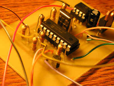
Constructed using wire-wrap technique.
Schematic prepared using Eagle 4.something.

So what am I doing with this little beauty? I can now, from the comfort of my computer room, monitor the temperature of three compost heaps in the back yard. I feel like I’m in a processing plant control room. This project, like most of my projects, was a spin-off from a related task. I had just got my two way RF link from my robot working well. I was starting to prepare my first summer compost heap and the light went on. A week later it was operational. Another week went into tweaking, playing and documenting.

TEMPERATURE TRANSMITTER DATA COLLECTION

The AT90S4433 has six 10 bit A/D inputs. I utilize all six. When the uC “wakes up” from idle mode, it turns the ADC module on, turns on the voltage divider power, waits 100 milliseconds and then reads the six ports. Each raw value is conditioned and converted to an 8 bit value for transmission.

Temperature is sensed using a 10K nominal thermistor. Thermistors change resistance with temperature so a resistor / thermistor bridge with a fixed 8K resistor was used. Thermistors have a large resistance change over the 32 to 200 F range I was interested in but the resistance vs. Temperature curve is logarithmic, not linear. I used a look-up table to linearize the signal and return a value directly in degrees F. Along the way I did discover that there is really no such thing as a standard “10K nominal” thermistor. Get a curve for the device you buy or you will have to calibrate it yourself.

Light is sensed with a Cadmium Sulphide photocell which also changes resistance, this time with light. I set up a divider with a 2K resistor. The reading swings from 4 or 5 in near dark to 251 in bright sunshine.

Battery voltage is sensed with a resistor divider connected directly to the battery. I installed a 5.1 V Zener on the input “just in case”. The signal is conditioned to return a value in tenths of a volt, i.e. 12 volts reads as 120. I could see that battery life could become a big issue, even with a device that normally draws only 10mA. A standard 800 mAh NiCad AA cell would theoretically last 80 hours. That’s only three days. I decided to use a 4600 Ah lithium laptop battery I had available. Its been running two weeks now and has dropped from 12.1 to 11.4 volts. Should still have two weeks left.

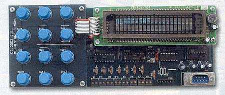
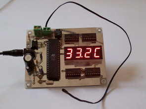
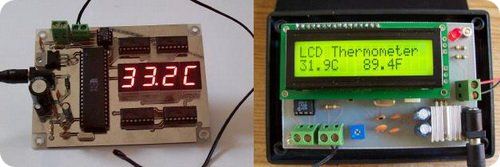
Here is what I see on my PC:

TEMPERATURE TRANSMITTER DATA COLLECTION

TEMPERATURE TRANSMITTER THE RADIOS

I used the TXM-433 transmitter and SILRX-433 receiver from Radiometrix. These are capable of operation at 4800 baud. I purchased these a couple years ago but there are now lower cost modules and higher speed modules available for the same price that I would consider. Here is the result of some research on sources of low cost RF modules. I have not used any of these and cannot vouch for their performance.

The receiving end takes more work, both physically and on the software side. If you are connecting to a PC then you must convert the signal from the RF receiver module to RS-232 using a MAX233 or equivalent. I have a two way set up configured which involves a transmitter and considerably more control complexity. Locate the receiver a ways away from your PC. I located mine outside by a corner of the house and find it works well with the transmitter all over the yard and all over the house.

If you fire up the receiver with no transmitter in operation and take a look at the serial port with a program such as HyperTerminal, you will see a barrage of strange characters. When the transmitter is activated, the receiver “syncs” with the transmitter and much of the noise disappears. So far so good. The problem is that we don’t want the transmitter powered up all the time – it would use far too much power. So when we power it down the garbage returns. Our little tidbits of data get lost in a sea of noise. This situation also exists when doing two way commuication. I attempted to use the CD (carrier detect) to determine if a valid signal had been received but I could not get it working properly. The PC program as supplied does not use CD.

The PC must, therefore, filter out the noise. The VBasic software reads every byte that is received, looking for a valid packet. The “Mailbox” protocol is designed to be simple yet robust enough that only valid data gets through. Each packet is formatted as “UUUUU ::AaDdDdDdDdDd…Xx”. The “U”s are 1010 characters that aid the receiver in synchronizing. The “::” are the start bytes. Until “::” is read, no data is passed. The receiver must know the length of the incoming packet. Once a valid packet is identified bytes are read until this length is reached, then a checksum byte is compared.

Another issue arising from the need to stay synchronized is that characters with long periods without changes, like 0 or 0xFF, can cause the receiver to lose sync. Radiometrics recommends using “5050” characters only – characters with a balance of ones and zeroes. This pretty well kills an 8 bit protocol. Instead I convert to ASCII Hex, then to 5050. ASCII Hex converts the transmitted byte to two characters, i.e. the number 168, which is equivalent to 0xA8 hex, is converted to “A” followed by “8”. “A” and “8” are in turn converted to 5050 before transmission and converted back at the other end. The PC software abandons any packet that contains non-5050 characters.

The Aa and Dd in the packet thus represent the two bytes of the address (ID) and the data. Xx represents the two bytes of the checksum.

At this point it has operated for two weeks, transmitting every half hour and I have not yet seen a bad packet get through. Line of site it may miss a packet a day. If the transmitter is located behind a building it may miss 25%. Because of the reflections it is difficult to predict performance. Sometimes moving the transmitter (or receiver) just a few feet will make a significant difference.

TEMPERATURE TRANSMITTER THE MICROCONTROLLER

I selected an Atmel AT90S4433 – has enough flash (4K), enough RAM(128 bytes) and has 6 A/D inputs, all in a 28 pin narrow package. The RAM turned out to be a bit tight due to the comm buffers and look-up tables – more on this later. I selected the lowest frequency crystal I had on hand, 4 MHz. I plan to try a 500KHz ceramic resonator to see if it lowers power consumption significantly.

As mentioned above, the uC normally is in an “idle” state. In “idle”, the clock still operates but the rest of the uC is shut down. The clock must run as it is used to calculate the transmit interval.

The long delay is generated using the method discussed in Atmel’s app note (#1268). The TCNT1 (16 bit T/C) output compare is physically tied to an input configured as the clock source for TCNT0 (8 bit T/C). This effectively results in a 24 bit counter, adjustable by the value stored in the TCNT1 output compare register. With a 4 MHz crystal, this gives delays up to 2 hours.

When TCNT0 reaches the overflow point an ISR is triggered which performs all the duties. Once the ISR is complete the program returns to the main loop where the sleep instruction is executed, putting the device back into “idle”.

On reset the uC is initialized – all ports are configured as required, unused pins are configured as inputs with internal pullups, the Mailbox interface routines are initialized and the UART set up. The Send rate DIP switch is read and a single packet is transmitted.

The main routine is called GetAndSend(). It turns on the sensor power, the A/D and the LED, waits for 100 ms, reads the ADC inputs, turns the sensor power, A/D and LED off, then transmits the data packet.

The Mailbox system architecture is multiple master/single slave with the data originating on the slave. I refer to it as multiport/multiprotocol serial RAM and is also applicable for uC to uC communications. The master is normally reading from specific locations in the slave, i.e. the address. It can be configured such that the master, in this case the PC, can also receive fixed length, unsolicited data packets from a slave. The routines used here, contained in mbRFslv.c and mbRFslv.h, are a subset of the complete two way comm software. The slave does not wait for a request but simply transmits its data packet as desired.

The SendMaster() routine loads the six data bytes into the comm buffer and calls SendToMaster(), defind in mbRFslv.c. The address must match whatever is configured at the PC end. SendToMaster adds the sync characters and the “::” start characters. Note that the send routine is not the usual write to the UART then wait till done. The send routine writes a byte then returns to the main routine. As each byte has been transmitted, a UART buffer empty ISR is run which transmits the next character. This method is not really required in this application but is necessary where the Mailbox routines exist within a busy application. Since I had operable, tested code I used it.

I did run into difficulties with the available RAM (128 bytes). GCC stores an initialized constant array in flash and RAM. There is no built-in facility to tell it to store the array in flash only. I had lookup tables for the thermistor curve and for the 5050 conversion. Along with the comm buffers this was rapidly using up my available RAM. I was able to find some routines in the progmem header that allowed the array to be designated as type prog_char. Data can be read from the table using the PRG_RDB macro. This was not ideal but worked satisfactorily. I was able to get this working for single bytes but not for integers. Other compilers apparently have a “flash” data type that accomplishes what I was looking for. It seems to me that the keyword “const” should direct the compiler to store only in flash. The GCC source code is attached.

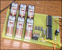
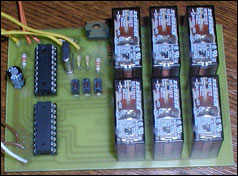
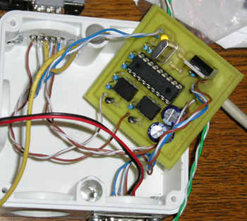
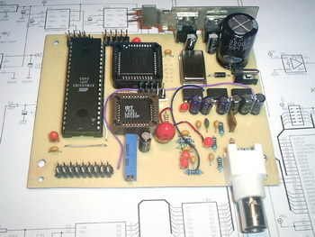
Construction: I like wire-wrap for one-off type projects such as this. I can wire-wrap a board like this in a couple hours. I find it to be highly reliable and changes can be made fairly easily. I now use a ground and power copper strip that I solder to – I find this goes a little quicker and results in a better power distribution system. I mounted the transmitter board directly on the lithium battery – makes a nice, tidy package. The board has an on-board 5V 78L05 regulator which is powered by the lithium batteries 9 to 12 volts. This could be made more efficient with an LDO regulator and lower voltage battery. The antenna is just a length of copper wire. The length is important – make sure it matches the quarter wave frequency of your transmitter/receiver. Check the documentation that comes with your RF modules.

The PC End: This article is primarily about the transmitter. I will discuss the receiving end software in enough detail to allow one to get the system operational.

I have found that the PC RS-232 port under Windows is not the most robust thing around. On my two PCs with four RS-232 ports only one will work as described here. This was three until I upgraded to XP from Win 98. The bottom line is that many PC ports have difficulty handling the barrage of garbage from the radio module. I have since constructed an interface board to handle this problem but I have not completed documenting this as of this writing.

The Mailbox software is a Windows based object written in Visual Basic 5.0. It’s basic purpose is to read from and write to slave Mailbox uCs using either an RF 5050 protocol (as used in this article) or an 8 bit protocol intended for hardwired applications. The program runs as an Active-X .exe server, which means it can operate standalone, or be called as a reference by another Windows application. The Windows application can request variables (bytes or 16 bit ints supported) from specific Mailbox addresses in the slave or send variables to specific addresses. The Mailbox software handles all of the packetizing, noise filtration, variable parsing, buffering activities.

The Mailbox software can also run in standalone mode. It will then startup with the main monitor screen active. This will allow you to send and receive data packets to/from specific addresses and monitor all incoming/outgoing data traffic. A data scroll screen is also included to watch the data progress over time.

The software needs to be installed like any other Windows application. You can run the program directly or it can be referenced as a component by another program. Also included are the source and executable files for MBTest, a simple program for testing Mailbox as an ActiveX server. The compatibility of this software has not been widely tested, but it does run on my two PCs.

The receiver board consists of the receiver module and an RS-232 level converter (MAX233). The board in the photos has both a receiver and transmitter and is set up for two way communications. Only the receiver is required for this application. I installed the board under a plastic weather guard with just the antenna poking through. I ran an RS-232 cable and a power wire from the PC to the receiver board. At the low baud rates used here you could likely run 100′ or more without problems. The receiver definitely works better when it is distanced from the PC.

Debugging: Debugging comm systems is always a challenge. There are many links in the chain and any one failure will bring the whole train to a halt. I recommend starting with a stripped down system – no radios, connect the transmitter directly to the PC port. You will need a CMOS to RS-232 level converter – I have one built into a serial cord – it’s ideal for this type of testing. Set the send rate at a fast interval, like once a second. If you have HyperTerminal or the Mailbox software running you should see a series of characters that looks like UUUU*ccDdDdDdDdXx once every second. If Mailbox is configured properly it should accept the packet and update the parsed data registers and the data scroll. If this is not working, try enabling the print_info() routine inside of main() and disable the Mailbox send routines.

If you have got this far its time to introduce the radios. Start with the radios together in the same room. I recommend having an oscilloscope on hand to monitor action at the various pins. If it doesn’t work recheck all your connections. I always like to have two of every component so I can check for functionality. Check for comm activity at the transmitter module data in pin and at the receiver module data out. Check if power is applied. Remember that power is disconnected at the transmitter until the transmit ISR is activated.

Operation: Now you can sit back and enjoy the excitement of watching real time data pour in. I set my transmitter up to send every half hour. It is connected to my spare PC, an old 233MMX, which perks along at about 18% load. I plan to try it on an even older 66MHz unit just for grins (and less power consumption). And now I can get back to the robot. Next project is a handheld communicator, with voice recognition, to converse with the robot, using the same RF methodology.

If you have any questions about the article, please contact the author at don@botgoodies.com.

source: WIRELESS RF TEMPERATURE TRANSMITTER ATmega8 AT90S4433 Wireless RF Temperature Transmitter project files alternative link: atmega8-at90s4433-wireless-rf-temperature-transmitter.rar alternative link3 alternative link4

ATMEGA162 LCD OSCILLOSCOPE CIRCUIT

$
0
0

A very nice project cost is a bit high in our country, even hard to find parts Atmel AVR microcontroller series dealing with this type of project is ideal for those who want to… Electronics Projects, ATMEGA162 LCD Oscilloscope Circuit “avr project, microcontroller projects, “

LCD OSCILLOSCOPE CIRCUIT

A very nice project cost is a bit high in our country, even hard to find parts Atmel AVR microcontroller series dealing with this type of project is ideal for those who want to learn about

I think part of that is difficult to have the most expensive LCD LMG6402PLF Hitachi LCD Screen LCD Oscilloscope ATMEGA162 microcontroller circuit board have all the details on

ATMEL AVR LCD OSCILLOSCOPE

ATMEL AVR LCD OSCILLOSCOPE

The oscilloscope is one of the the most important tools to be used by any electronics hobbyist but not everybody can afford to have one. As commercial scopes are often too expensive, almost every electronics hobbyist thought at a certain time to build one from scratch. The classical oscilloscope (cathode ray tube) is difficult to build at home because of its size, mechanical fragility, high voltages presence, etc. An alternative solution is the modern “PC oscilloscope”, having the advantage of post-processing and recording capabilities, and kind of reduced complexity. However, this solution is often non-portable, expensive (requires an PC) and dangerous for the PC if not isolated from it’s chassis. The third solution, commonly used these days by all commercial oscilloscope manufacturers, is the digital oscilloscope with LCD screen. Therefore, the authors decided to use this solution, and tried to develop it using common parts from today’s component retailers.

Maximum sample frequency: 40MSPS
Maximum input frequency: 5MHz
Maximum displayed frequency without aliasing: 10MHz
Input circuit bandwidth: 20MHz
Display resolution: 240×128 total, trace resolution 200×125
Sensitivity: 40mV/div
Coupling: DC
Input impedance: 10K
Power supply: single DC source 8V..10V, 1A
No incremental mode
Time base: 1s/div, 500ms/div, 200ms/div, 100ms/div, 50ms/div/, 20ms/div, 10ms/div, 5ms/div, 2ms/div, 1ms/div, 500us/div, 200us/div, 100us/div, 50us/div, 20us/div, 10us/div, 5us/div, 2us/div, 1us/div, 500ns/div
Trigger: digitally adjustable
Trace offset: digitally adjustable

source: LCD OSCILLOSCOPE CIRCUIT LCD Oscilloscope Circuit files alternative link:atmega162-lcd-oscilloscope-circuit.rar alternative link3 alternative link4

WHEELS BIKE LIGHT CIRCUIT

$
0
0

ATTINY2313 a flashy accessory for your bike 74LS595N 25LC080P a good practice based on the software with all the details have pcb diagram hex code schema (schema) and PCBs (br) Latest eaglecad prepared by…Electronics Projects, Wheels bike light circuit “avr project, microcontroller projects, “

WHEELS BIKE LIGHT

ATTINY2313 a flashy accessory for your bike 74LS595N 25LC080P a good practice based on the software with all the details have pcb diagram hex code schema (schema) and PCBs (br) Latest eaglecad prepared by

WHEELS BIKE LIGHT (1)

Spoke POV is an easy-to-make electronic kit toy that turns your bicycle wheel into a customized display! The project includes a free schematic design, open software for uploading and editing stored bitmap images, and a high-quality kit with all the parts necessary to build your own.

Source: WHEELS BIKE LIGHT CIRCUIT – Wheels bike light Alternative link: Wheels bike light vircuit.rar alternative link2


MONITOR AUDIO RADIO SPECTRUM ATMEGA8

$
0
0

Atmega8-16 ac circuits with LEDs monitor the spectrum vu-meters of the advanced state of our LCD and LED spectrum analyzer circuit looks very nice variety of testing everything in the middle video There are…Electronics Projects, Monitor Audio Radio Spectrum Atmega8 “atmega8 projects, avr project, microcontroller projects, “

MONITOR AUDIO RADIO SPECTRUM

Atmega8-16 ac circuits with LEDs monitor the spectrum vu-meters of the advanced state of our LCD and LED spectrum analyzer circuit looks very nice variety of testing everything in the middle video There are three different applications of the audio spectrum monitor’s dot matrix LED module It’s application.

source: MONITOR AUDIO RADIO SPECTRUM ATMEGA8 – Monitor Audio Radio Spectrum Alternative link: audio-radio-spectrum-monitor.rar alternative link3


AVR TEMPERATURE MEASUREMENT SYSTEM

$
0
0

Atmel AVR, Atmel microcontroller series with a super “Temperature Control Measurement System” 16 sensor inputs 4 alarm inputs and the computer’s connection. Temperature measurement, alarm, an exemplary application in the PC communication This measuring… Electronics Projects, AVR Temperature Measurement System “avr project, microcontroller projects, “

AVR TEMPERATURE MEASUREMENT

Atmel AVR, Atmel microcontroller series with a super “Temperature Control Measurement System” 16 sensor inputs 4 alarm inputs and the computer’s connection. Temperature measurement, alarm, an exemplary application in the PC communication

This measuring system is used to record the data of up to 24 temperature sensors in the range of -55 ° C to +125 ° C, 3 humidity sensors and an air pressure sensor. Addition, there are still 4 alarm inputs are available, where switching contacts can be connected. The project consists of several components: the sensor module 2, the sensor module 3 with additional air pressure sensor, the small display module 1, the large display module 2a, the LED display module 3 and the PC program “AnzKom” and a web module. The sensor modules record the temperatures and humidities over 1-Wire sensors and monitor the alarm inputs. The processed data are then sent cyclically via an RS-232 interface to the display modules, which in the case of the display module 2a can also record the data represents a clear and. With the “AnzKom” program can be transferred, conveniently displayed and analyzed the stored data of the display module 2a. The Web module also provides the ability to query current and stored data via web-browser world.

AVR TEMPERATURE MEASUREMENT(1) AVR TEMPERATURE MEASUREMENT(2) AVR TEMPERATURE MEASUREMENT(3)

Source: AVR TEMPERATURE MEASUREMENT SYSTEM AVR Temperature Measurement System files Alternative link: avr-temperature-measurement-system.rar alternative link2 alternative link3

OLD CD ROM TRACK PLAYER WITH MICROCONTROLLER

$
0
0

Old Cd Rom in handy if you want to make a Track Player PIC16F877 and AT89C51, AT89S52 controllers are made with good projects. Add to My Cdrom the features of the project with PIC16F877:… Electronics Projects, Old Cd Rom Track Player with Microcontroller “avr project, microchip projects, microcontroller projects, pic16f877 projects, “

OLD CD ROM TRACK PLAYER

Old Cd Rom in handy if you want to make a Track Player PIC16F877 and AT89C51, AT89S52 controllers are made with good projects. Add to My Cdrom the features of the project with PIC16F877: Open, Close, forward, backward, Start, Stop, Eject, Close, Info cdrom audio output is also made with a simple ANFIS to strengthen the TDA2822 is on.

PIC16F877 TRACK PLAYERPIC16F877 TRACK PLAYER

AT89S52 TRACK PLAYER

AT89S52 TRACK PLAYER


Add to My Cdrom with AT89S52 control circuit that features: Eject, Stop, Forward, Back, Start, wait, adds remote control features

8051 TRACK PLAYER

8051 TRACK PLAYER

Source: OLD CD ROM TRACK PLAYER WITH MICROCONTROLLER PIC AVR Microcontroller Old Cd Rom Track Player circuits files: old-cd-rom-track-player-with-microcontroller.rar alternative link2 alternative link3

MICROCONTROLLER CONTROLLED ROBOT PROJECTS

$
0
0

Multi-robot projects have been realized with the microcontroller. In addition to professional practice ‘projects have simple robot Most of the projects in the PIC16F series microcontrollers used ATMEL series over with no project varieties… Electronics Projects, Microcontroller Controlled Robot Projects “avr project, microcontroller projects, “

MICROCONTROLLER CONTROLLED ROBOT

Multi-robot projects have been realized with the microcontroller. In addition to professional practice ‘projects have simple robot Most of the projects in the PIC16F series microcontrollers used ATMEL series over with no project varieties plenty sumo robots, line following robot, rope climbing robots, crawling robots also Turkish thoroughly robotics Anlatımları interested in this subject people to work will cleave.

A FEW EXAMPLES ROBOT PROJECT

A FEW EXAMPLES ROBOT PROJECT (1) A FEW EXAMPLES ROBOT PROJECT (2) A FEW EXAMPLES ROBOT PROJECT (3) A FEW EXAMPLES ROBOT PROJECT (4) A FEW EXAMPLES ROBOT PROJECT (5) A FEW EXAMPLES ROBOT PROJECT (6) A FEW EXAMPLES ROBOT PROJECT (7) A FEW EXAMPLES ROBOT PROJECT (8)

6-legged robot made using 16f84
A small robot board with the AVR
step by step, solar-powered robots \ Robotics & Electronics
Balibot, the Inverted Pendulum Robot
Bill’s Boat mini sumo robots
C-52EVB Robot Controller
rope climbing robot bay
jstamp Robot
Line Follower Robot
Mini Sumo Robot
Mobile robots – (thesis)
Robot Sanson \ AMUR by »Robot Sansón
reptile robot
THE ROBOT
PDA Robotics
Watch Cartoon robots
super small line follower
line following mobile robots

Source: MICROCONTROLLER CONTROLLED ROBOT PROJECTS Microcontroller Controlled Robot Projects download: microcontroller-controlled-robot-projects.raralternative link2 alternative link3

MICROCONTROLLER CONTROLLED BATTERY CHARGING CIRCUITS

$
0
0

PIC Series Microcontroller ATMEL etc. Battery battery charger integrated circuits made using the PIC16F819, PIC16F84, PIC16F876, ATMEGA32, AT90S4433-PCR, AT90S1200-P, based on the ATmega8’s 7units applications Microcontroller controlled battery charging circuits all files: microcontroller-controlled-battery-charging-circuits.rar alternative… Electronics Projects, Microcontroller controlled battery charging circuits “avr project, battery charger circuit, microchip projects, microcontroller projects, “

BATTERY CHARGING CIRCUITS

PIC Series Microcontroller ATMEL etc. Battery battery charger integrated circuits made using the PIC16F819, PIC16F84, PIC16F876, ATMEGA32, AT90S4433-PCR, AT90S1200-P, based on the ATmega8’s 7units applications

BATTERY CHARGING CIRCUITS (1) BATTERY CHARGING CIRCUITS (2) BATTERY CHARGING CIRCUITS (3) BATTERY CHARGING CIRCUITS (4) BATTERY CHARGING CIRCUITS (5) BATTERY CHARGING CIRCUITS (6) BATTERY CHARGING CIRCUITS (7)

Source: CONTROLLED BATTERY CHARGING CIRCUITS  Microcontroller controlled battery charging circuits all files: microcontroller-controlled-battery-charging-circuits.rar alternative link2 alternative link3 alternative link4

MICROCONTROLLER CONTROLLED DIGITAL POWER SUPPLY CIRCUITS ARCHIVE

$
0
0

NXP80C31, PIC16F876, PIC12F629, PIC18F452, PIC16F876, PIC16F870, PIC18F252, HC908QT4 made with integrated power sources in various voltage and power MCU of microcontrollers in power electronics used always been interested 🙂 
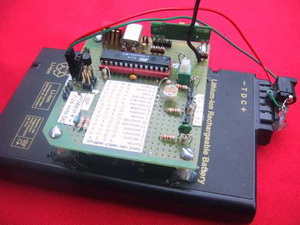
Unfortunately this type MCU, PIC,… Electronics Projects, Microcontroller Controlled Digital Power Supply Circuits Archive “avr project, microcontroller projects, “

DIGITAL POWER SUPPLY CIRCUITS

NXP80C31, PIC16F876, PIC12F629, PIC18F452, PIC16F876, PIC16F870, PIC18F252, HC908QT4 made with integrated power sources in various voltage and power

MCU of microcontrollers in power electronics used always been interested 🙂 Unfortunately this type MCU, PIC, ATMEL a controlled power supply did not do it to do Yade get the idea people who want a few examples MCU controlled digital power supply has a project.

DIGITAL POWER SUPPLY EXAMPLE

DIGITAL POWER SUPPLY EXAMPLE (9) DIGITAL POWER SUPPLY EXAMPLE (8) DIGITAL POWER SUPPLY EXAMPLE (7) DIGITAL POWER SUPPLY EXAMPLE (6) DIGITAL POWER SUPPLY EXAMPLE (5) DIGITAL POWER SUPPLY EXAMPLE (4) DIGITAL POWER SUPPLY EXAMPLE (3) DIGITAL POWER SUPPLY EXAMPLE (2) DIGITAL POWER SUPPLY EXAMPLE (1)

Source: DIGITAL POWER SUPPLY CIRCUITS  Microcontroller Controlled Digital Power Supply Circuits Archive all files: microcontroller-controlled-digital-power-supply-circuits-archive.rar alternative link2 alternative link3

MICROCONTROLLER GSM ALARM AND CONTROL CIRCUITS

$
0
0

Now quite a popular topic with Cell Phone Control with Microchip pic series for those who want to do these types of projects that could give clues will limp a few projects, including projects… Electronics Projects,Microcontroller GSM Alarm and Control Circuits “avr project, microcontroller projects, “

GSM ALARM AND CONTROL CIRCUITS

Now quite a popular topic with Cell Phone Control with Microchip pic series for those who want to do these types of projects that could give clues will limp a few projects, including projects located in Atmella in 1

Pcb circuit connected pc with AT90S2313 asm hex file and available software

GSM ALARM AND CONTROL CIRCUITS(1)

Emergency equipment is often equipped are various signs of tampering. The easiest is to run the audible signal or optical, the more advanced can given its status over the Internet or telephone. Presented in this article to your amateur alarm, which can send information on the attached by short text messages, so-called SMS. For model needs the company I used GSM modem Wavecom, but you can use any phone phone. Perhaps its use will require a solution to the problem of power and how encoding text messages, but it is possible and feasible in terms of electronics workshop – amateur.

The whole program has been constructed and compiled by AVR STUDIO 4. This is a complete environment for writing and applications for the AVR microcontrollers. The line RESET, MISO, MOSI and SCK przylutowałem microcontroller interface and programmer using ISP program and tested layout. This is a very comfortable not only for the amateur electronics, method. Allows you to run applications in real – its operating environment. The program occupies 128 bytes of EEPROM memory in the variables defined by the user. Their list can be found in Table takes 1,019 words double-byte, 2038 is 2048 bytes of program memory AT90S2313. Unfortunately, there is already too much space to implement the new functions or more messages. You can only be done
cost of removing or optimizing existing ones.

GSM ALARM AND CONTROL CIRCUITS(2)

It is a device that will include / exclude consumers when he sent the SMS. I did. The device consists of a PIC microcontroller, one ULN2803A (order transistor) power relays, and 6 relays. Of course, a few resistors and capacitors, three prekidačića, crystal and two LE diodice. The device was tested on Siemens phones, S25 and C35i. You should work with the other, and with all other GSM device which can be attached to the serial communication. Such devices are, for example.: All-Ericsson, and only with them I have not yet tested.

GSM ALARM AND CONTROL CIRCUITS(4)

GSM Call Alarm is a device that uses a number of target position Siemens or Ericsson Mobile Phone (19200 bauds RS232) and sensory input is 1 and one entry – the state. If state = 0V then the device is “active” and follow the state senzorskog inputs. The device is “disabled” otpajanjem on / off (the state) with the mass of inputs (0V), or connect to the + half of power. Sensory input also respond to 0V.

GSM ALARM AND CONTROL CIRCUITS(3)

SMS Alarm is a very simple device. To send a message uses a Siemens phone has 5 inputs – is sending 5 different messages. For each sensor uprogramiramo appropriate message you wish to receive the mobile when it is activated. Programming is done via the PC’s corresponding program which is attached in the archive.

Source:GSM ALARM AND CONTROL CIRCUITS  Microcontroller GSM Alarm and Control Circuits: microcontroller-gsm-alarm-and-control-circuits.raralternative link3


UNINTERRUPTIBLE POWER SUPPLY UPS AT90S8515

$
0
0

PWM with AT90S8515 a good practice to understand the logic can give 200w Power should be developed for more The driver circuit method used in section H-Bridge driver integrated HIP4080 I have in the… Electronics Projects, Uninterruptible Power Supply UPS AT90S8515 “avr project, microcontroller projects, “

UNINTERRUPTIBLE POWER SUPPLY

PWM with AT90S8515 a good practice to understand the logic can give 200w Power should be developed for more

The driver circuit method used in section H-Bridge driver integrated HIP4080 I have in the market

The schema of the latter and ‘very simple, despite the Difficulties’ linked to power and it’s not particularly interesting because of the microprocessor controller (PIC).

I wanted than to make something similar but with reduced power to 220V 200W max. I state that my purpose and ‘only experimental, there are, of course, how best to developer a circuit like that.

The diagram and ‘a bit’ more complex than that Article, ’cause using the circuit configuration of power MOSFETs in H-Bridge’ with its driver which in my opinion ‘more’ efficient management instead and ‘Entrusted to a AT90S8515 microcontroller which reads and displays, among other things, the various parameters Involved (voltages, currents etc.

UNINTERRUPTIBLE POWER SUPPLY(1)

UNINTERRUPTIBLE POWER SUPPLY(2)

Source: UNINTERRUPTIBLE POWER SUPPLY UPS AT90S8515 Uninterruptible Power Supply UPS AT90S8515 alternative link uninterruptible-power-supply-ups-at90s8515.rar

GAS DETECTOR CIRCUIT ATTINY45

$
0
0

Gas sensors are employed in a wide range of applications in the fields of safety, health, instrumentation etc… Common examples are domestic/commercial alarms for explosive or toxic gases or in automotive application, as gas… Electronics Projects, Gas Detector Circuit ATtiny45 “avr project, microcontroller projects, “

GAS DETECTOR CIRCUIT

Gas sensors are employed in a wide range of applications in the fields of safety, health, instrumentation etc… Common examples are domestic/commercial alarms for explosive or toxic gases or in automotive application, as gas leakage detectors for LPG powered cars and exhausts detectors inside any fuel-powered truck/car. Such sensors, nowadays, are found also in applications involving air quality control systems and pollution monitoring.

Today’s sensors, while featuring an high sensitivity to a wide gases variety, are very compact in size and have significantly reduced their power consumption to better adapt to portable solutions.
Building a system with a gas sensor is not as easy as it could appear. Despite the sensor could be treated basically as a variable resistor (which value depends on gas concentration in air) the practical implementation in a project should be done considering some design rules, especially if the final circuit is a device to be used in a field where reliability is strongly required (e.g. safety). As an example the internal elements of a sensor (heater and gas sensitive resistors) have to be constantly kept under control to avoid failures leading to a wrong alarm indication; furthermore, if the application needs to achieve a good measurement accuracy, factors like environment temperature, sensor life etc… have to be taken into account.

GAS DETECTOR CIRCUIT(1)

All those features and controls require to introduce in the project a certain amount of external circuitry (including components like comparators, temperature sensor, spare logic etc…) to carry out functions such us temperature compensation, sensor heating control, sensor warm-up time, sensor life time check and so on…

This project aims to show how the AVR ATtiny45, by means of its peripherals such us ADC, timers and internal temperature sensor, fits perfectly this application and it can be employed to replace a lot of external components while adding extra functionalities at a cost comparable to a simple integrated

Source: GAS DETECTOR CIRCUIT  Gas Detector Circuit ATtiny45 project files: gas-detector-circuit-attiny45.rar alternative link2 alternative link3

AT90S1200 D.D.S. FUNCTION GENERATOR

$
0
0

The presented project is a function generator for sinusoidal and square signals production. The output frequency covers the range from 10 Hz to 100 KHz with a step of 2 Hz. The waveform synthesis… Electronics Projects, AT90S1200 D.D.S. Function Generator “avr project, microcontroller projects, “

D.D.S. FUNCTION GENERATOR

The presented project is a function generator for sinusoidal and square signals production. The output frequency covers the range from 10 Hz to 100 KHz with a step of 2 Hz.

The waveform synthesis is based on the D.D.S. technique (Direct Digital Synthesis) and the output frequency is selected through a microcomputer with an embedded thumb wheel keyboard.

FUNCTION GENERATOR TECHNICAL SPECIFICATIONS

Output Frequency: 10 Hz – 100 KHz (step 2 Hz)
Output Voltage:
Sinus: 0 – 20 Vp-p
Square: 0 – 20 Vp-p
TTL: 5 V
Output Resistance: 1 KOhms

FUNCTION GENERATOR SINUSOIDAL WAVEFORM DIRECT DIGITAL SYNTHESIS

A complete sinusoidal waveform can be synthesized through a D.D.S. system. This system uses a group of 2^21 phases (time slots) and a 16 bit data latch defines how many of them will be contained between two successive synchronization pulses. If the 16 bit data latch contains low numerical values then the output frequency will be low and if the 16 bit data latch contains high numerical values then the output frequency will be high.

FUNCTION GENERATOR SINUSOIDAL WAVEFORM (1)

FUNCTION GENERATOR SINUSOIDAL WAVEFORM (2)

source: D.D.S. FUNCTION GENERATOR AT90S1200 D.D.S. Function Generator alternative link at90s1200-d-d-s-function-generator.rar alternative link2

Ultrasonic Radar Model Using Microcontroller ATmega128

$
0
0

The circuit described here demonstrates the working of a radar system. It uses ultrasonic waves to detect an object and measure its distance and angular position, and displays the same on a 20×4 LCD screen. — Ashutosh M. Bhatt is an M. Tech in embedded systems (gold medalist). Currently, he is lecturer in electronics and radio engineering at Government Polytechnic, Jamnagar, Gujarat. He has been working on embedded systems since the last ten years

Radar systems have a number of defence as well as civil applications. Air traffic control uses radars to track aircrafts on the ground and in the air, and to guide planes for smooth landings. Police use radars to detect the speed of passing vehicles. Geologists use radars to map the Earth and other planets. Military uses these for surveillance. Meteorologists use radars to track storms, hurricanes and tornadoes. The list is endless.

A radar system consists of a transmitter that transmits a beam towards the target, which is then reflected by the target as an echo signal. The reflected signal is received by a receiver. This receiver processes the received signal and provides such information as the presence of a target, distance, position (moving or stationary) or speed, which is displayed on a display unit.

Microcontroller based ultrasonic radar circuit

Actual radar systems are built with high-power transmitters and receivers, huge antennae, complex processing systems using digital signal processors and large displays.

This microcontroller based ultrasonic radar circuit demonstrates the working of a radar system. It uses ultrasonic waves to detect an object and measure its distance and angular position, and displays the same on a 20×4 LCD screen. It can detect multiple objects at different angles and distances as new objects are detected. This means that the distance and angle of all objects are displayed one by one on the same LCD screen.

The block diagram of an ultrasonic radar system is shown Fig. 1. The system includes an ultrasonic distance measurment (UDM) sensor, LCD panel, opto interrupt sensor, a motor driver, DC motor, buzzer and LEDs. The schematic of the system is shown in Fig. 2.

Source: Ultrasonic Radar Model Using Microcontroller ATmega128

RFID based Attendance System

$
0
0

Most educational institutions’ administrators are concerned about student irregular attendance. Truancies can affect student overall academic performance. The conventional method of taking attendance by calling names or signing on paper is very time consuming and insecure, hence inefficient. Radio Frequency Identification (RFID) is an interesting solution in such cases. RFID based attendance system is one of the solutions to address this problem.

Applications of RFID

This system can be used to take attendance for student in school, college, and university. It also can be used to take attendance for workers in working places. Its ability to uniquely identify each person based on their RFID tag type of ID card make the process of taking the attendance easier, faster and secure as compared to conventional method.

The system can be connected to the computer through RS232 or Universal Serial Bus (USB) port and store the attendance taken inside database. An alternative way of viewing the recorded attendance is by using HyperTerminal software. A prototype of the system has been successfully fabricated. Radio frequency technology is used in many applications. RFID tags are of two types

Passive tags contain 13 digit number tag inbuilt in it, whereas active tags are read/write tag i.e. one can read from the tag and write to the tag.

This project uses a passive tag in making the RFID based attendance system. In real time, one can issue active tags to the students, with their roll numbers as their tags. RFID reader contains a copper winding in it. This winding acts as an antenna.

Working of RFID based attendance system

When a person with RFID tag or transponder enters in the range of RFID reader, the RF field induces voltage in the coils of tag. The range can be set by using the appropriate reader of appropriate frequency. This induced field supplies the voltage in case of passive tags and act as a battery in that case. If active tags are used then the case will be different as they have battery of their own.

Due to interaction of tag with reader 12 characters from tag are sent to controller. These 12 characters are sent to controller via serial communication. Before this controller is loaded with a program. In controller data of employee are saved. In our case data‘s of two employees are saved i.e. tag number and name. When we provide power supply to the circuit, the circuit switches on and “RFID BASED ATTENDANCE SYSTEM” is displayed on LCD.

When 12 characters are transferred to controller, the controller matches the characters with the saved characters. If the characters are matched then controller sends ‘1’ to green LED and time & date at time of entrance is fetched and stored. If characters do not match with the saved characters, the controller sends ‘1’ to red LED and displays tag number along with a string “ERROR”. This way it can be done number of times for different employees. Similarly there will be number of entries, valid or invalid. At the end of day, circuit can be connected to PC through RS232. And complete data is transferred to the computer on HYPERTERMINAL/TERATERM.

Component List

  • Printing PCB
  • ATmega32 Microcontroller
  • Crystal Oscillator
  • 3v Lithium Battery
  • DS1307 RTC IC
  • MAX232
  • ISP CONNECTOR
  • RFID Tags
  • RFID Reader
  • Capacitor
  • Voltage Regulator IC 7805
  • LED
  • Connecting wires
  • LCD 16×2
  • Resistors

Source: RFID based Attendance System

Viewing all 1082 articles
Browse latest View live