Three-fourths of the earth is water, out of which 97 per cent is saline (in oceans, seas and groundwater). The remaining 2.5 per cent to 2.75 per cent is fresh water, out of which 1.75 per cent to two per cent is frozen in glaciers, ice and snow. Fresh groundwater and soil moisture constitutes only 0.7 per cent to 0.8 per cent. Less than 0.01 per cent, available as surface water in lakes, swamps and rivers, is available to us as drinking water. It is therefore imperative that systems are in place for managing this precious and scarce resource.
Water-level indicators for water-storage tanks are mostly mechanical contraptions. Steel wires, pulleys and rails get rusted as these are in continuous contact with water and air, resulting in unreliable operation. Contactless sonar-level metres are there but their high cost is a deterrent.
In this article, a sonar contactless, wireless water-level indicator, which can be fabricated for less than Rs. 2500, has been described. It is capable of measuring water levels up to four metres with an accuracy of less than 5mm.
Circuit and working
The water-level indicator has two units: transmitter unit and receiver unit. The circuit diagram of the transmitter unit is shown in Fig. 1. It is built around ATmega328P microcontroller (MCU) (IC1) with Arduino Uno bootloader, sonar sensor HC-SR04 connected at CON1, 433MHz transmitter (TX1), voltage regulator 7805 (IC2) and a few other components. a long spiral antenna is used for enhancement of its range.
Attach the contactless sonar sensor at a strategic location on the tank so that it can always get the reflected signal from the water surface. The best place would be at the centre of a circular tank’s lid on top, or at the intersection of the diagonals of a rectangular tank’s top. The calculated tank level will then be transmitted with a coded authorisation to the receiver unit.
An ultrasonic ranging module provides 20mm to 5000mm non-contact measurement facility. Ranging accuracy is 3mm and aperture angle is 15°. Since we are measuring the level in centimetres in the form of an integer, our accuracy level is maximum 5mm. Even a 1cm level change will be seen very clearly, as every second it takes eight readings, which are then averaged out to get better accuracy.
Circuit diagram of the receiver unit is shown in Fig. 2. It is built around ATmega328P MCU (IC3) with Arduino Uno bootloader, voltage regulator 7805 (IC4), 4×16 alphanumeric display (LCD1), 433MHz receiver (RX1) and a few other components. The receiver checks the code word sent by the transmitter unit and displays the tank level on the LCD.
If the transmitter stalls or its power supply gets interrupted, there is no way for the receiver to find out that the incoming signal is no longer valid. To circumvent this problem, a counter has been provided on the right side of the LCD display. If the counter does not move, or it stops, it means that the incoming signal has stalled. Blinking of LED2 connected on pin 19 will stop, too.
Control relay and contactors can be connected on spare pins of ATmega328P, which finally controls the running of the water pump. Since there is no physical contact used in the sensory system, it will be operational without any interruption.
Software Software comprises one remote_sonar_water_level_transmitter.ino file and one remote_sonar_water_level_receiver.ino file, besides some header files of Arduino. All are packed in the resource directory. Add these libraries to Arduino and upload the two files in the respective transmitter and receiver units.
An actual-size, single-side PCB of the transmitter unit is shown in Fig. 3 and its component layout in Fig. 4. An actual-size, single-side PCB of the receiver unit is shown in Fig. 5 and its component layout in Fig. 6.
After assembling the two units, switch on the power supply of both the units. If the receiver receives the transmitted signal, LED2 will start blinking. The two small digit counters on the right top of the LCD will start changing and the water level (in centimetres) will show on the left-top position. Keep the small spiral antennae in vertical position to have the best radiation.
A Temperature Controlled DC Fan is a system which automatically turns on a DC Fan when the ambient temperature increases above a certain limit.
Generally, electronic devices produce more heat. So this heat should be reduced in order to protect the device. There are many ways to reduce this heat. One way is to switch on the fan spontaneously.
This article describes two such circuits that automatically, switches the fan when it detects the temperature inside the device greater than its threshold value.
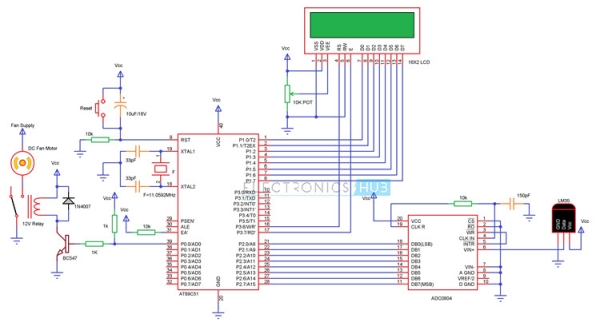
Circuit 1 Temperature Controlled DC Fan using 8051
Circuit Diagram
Principle
The project works on the principle of Analog to Digital Conversion. The Analog data from the LM35 temperature sensor is given to the analog to digital converter ADC0804.
The analog output of the temperature sensor will vary at 10mV per degree Celsius.
ADC0804 is an 8-bit ADC. For a reference voltage of 5V, we’ll get a resolution of 5V/28 = 20mV. Which means, this is the minimum change in the analog value from the sensor which is recognisable by the ADC IC.
As per the changes in the temperature, the output of the ADC is generated. The digital output of the ADC is given to Microcontroller to calculate the temperature and control the fan accordingly.
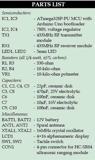
Components
Microcontroller Section
AT89C51 Microcontroller
AT89C51 Programmer Board
11.0592 MHz Quartz Crystal
33pF Ceramic Capacitor
2 x 10KΩ Resistor
10µF Electrolytic Capacitor
Push Button
16 X 2 LCD Display
10KΩ POT
Temperature Sensor Section
LM35
ADC0804
10KΩ Resistor
150pF Ceramic Capacitor
1KΩ x 8 Resistor Pack
Load Section
2N2222 NPN Transistor
1N4007 Diode
12V Relay
1KΩ Resistor
Fan
Configuring ADC0804 for this Project
The configuration of the ADC0804 is explained here. First, we need to connect the 5V regulated power supply to the Vcc pin (Pin 20). Then, connect the analog and digital ground pins (Pins 8 and 10) to the GND.
In order to use the internal clock, we need to connect a 10KΩ resistor between CLK IN (Pin 4 and CLK R (Pin 19) and then, connect a 150pF cap between pins 4 and GND to complete the oscillator circuit.
The CS pin (Pin 1) is connected to GND to enable the ADC.
In order to read the data from the ADC continuously by the microcontroller, we need to connect the RD pin (Pin 2) to the GND.
For the ADC to continuously read the analog data from the sensor, we need to short the Write pin (Pin 3) with the Interrupt pin (Pin 5).
The analog output of the sensor (LM35) is connected to the Vin+ (Pin 6) of the ADC. The negative analog input pin i.e. Vin- of the ADC is connected to the GND.
The converted digital data which is an 8-bit data will be available at DB0 to DB7 (Pins 18 to 11).
Circuit Design
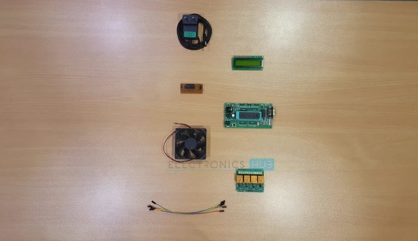
The main components of the project are 8051 Microcontroller, 16×2 LCD Display, LM35 Temperature Sensor, ADC0804, Relay and Fan.
The basic connections with respect to microcontroller include clock, reset and EA. Clock consists of an 11.0592 MHz crystal and two 33pF capacitors. The reset circuit consists of a 10µF capacitor, 10KΩ resistor and a push button. The EA pin is pulled high with a 10KΩ resistor.
Now we’ll see the connections with respect to other components.
For the LCD display, a 10KΩ pot is connected to contrast adjust pin. The three control pins of the LCD are connected to the pins P3.6, GND and P3.7.
The 8 data pins of the LCD are connected to PORT1 of the microcontroller.
The basic connections with respect to ADC are explained in its configuration. The 8 digital outputs of the ADC must be connected to PORT 2 of the microcontroller.
The next component we are going to connect is LM35. Connect the data pin of the LM35 to the analog input pin i.e. Pin 6 of ADC.
Finally, we need to connect the Relay circuit consisting of resistor, transistor and relay to the PORT0 of the microcontroller with PORT 0 pulled-up externally.
Connect the input of relay i.e. base of the transistor to P0.0 pin of the microcontroller.
Working
The aim of this project is to design a temperature controlled fan using 8051 microcontroller, in which the fan is automatically turned ON or OFF according to the temperature. The working of the project is explained here.
In this circuit, the LM35 temperature sensor will give continuous analog output corresponding to the temperature sensed by it. This analog signal is given to the ADC, which converts the analog values to digital values.
The digital output of the ADC is equivalent to sensed analog voltage.
In order to get the temperature from the sensed analog voltage, we need to perform some calculations in the programming for the microcontroller.
Once the calculations are done by the microcontroller according to the logic, the temperature is displayed on the LCD. Like this, the microcontroller will continuously monitor the temperature.
If the temperature exceeds more than 50 deg Celsius (as per the code), the microcontroller will turn on the relay to start the fan. If the temperature drops below 40 deg Celsius (as per the code).
Circuit 2 Temperature Controlled DC Fan using ATmega8
Circuit Diagram
Circuit Principle
The main principle of the circuit is to switch on the fan connected to DC motor when the temperature is greater than a threshold value.
The microcontroller continuously reads temperature from its surroundings. The temperature sensor acts as a transducer and converts the sensed temperature to electrical value. This is analog value which is applied to the ADC pin of the microcontroller.
The ATmega8 microcontroller has six multiplexed ADC channels with 10 bit resolution. The analog value is applied to one of the input ADC pins. Thus conversion occurs internally using successive approximation method.
For ADC conversion, internal registers should be declared. The ADC pin outputs a digital value. This is compared with the threshold value by the controller which switches the fan if value is greater than threshold.
The LM35 is an integrated circuit sensor that can be used to measure temperature. The output voltage of this sensor is proportional to the temperature in degree Centigrade. The output voltage of the LM35 will vary at a rate of 10mV per degree Celsius.
Usually, the range of the LM35 temperature sensor is from -55 deg C to +150 deg C. To measure this full range of temperatures i.e. from negative range to positive range, we need to connect an external resistor between the data pin and a negative supply of Vcc.
Any way, we are not going to consider the negative temperature range in this project. So, under normal operating conditions, we can measure the temperature in the range from +2 deg C to +150 deg C.
ADC
All the parameters of nature are of analog i.e. most of the data in the real world is characterised by analog signals. For instance, if the temperature of the room is measured.
The room temperature varies with time continuously. This measured signal, which continuously changes with time say from 1sec , 1.1sec , 1.2 sec and so on is called Analog signal.
In order to manipulate the real world data using a microprocessor or a microcontroller, we need to convert the analog signals to the digital signals, so that the processor or controller will be able to read, understand and manipulate the data.
Atmega8 has internal Analog to digital converter.
Declaring of internal ADC Registers
The ATmega8 microcontroller internally has three register namely ADMUX , ADCSRA, ADC data registers. Analog to digital converter is of 10 bit resolution.
Initially, select the reference voltage to the ADC using ADCMUX register.
Select REFS0 and REFS1 values in ADMUX register to set the reference voltage.
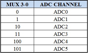
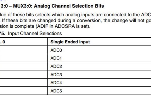
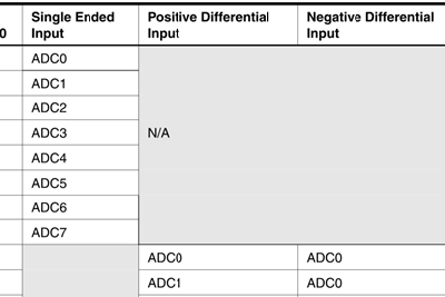
Now select the ADC channel using MUX0-MUX3 bits in ADMUX register. Below given table shows the binary value to be placed in the MUX0-MUX3 bits to select a channel.
If the sensor is connected to ADC0 channel with AVCC with external capacitor at AREF pin, then the binary value to be assigned to the ADMUX register is ADMUX=0b01000000.
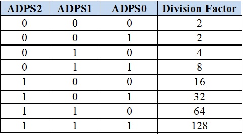
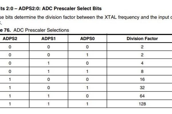
Now select the pre scalar value using ADPS0, ADPS1 and ADPS2 bits of ADCSRA register and also enable ADC using ADEN bit in ADSCRA register.
The following bits decide the division factor between XTAL frequency and input clock of ADC:
Now enable start conversion bit that is ADCSC in ADCSRA register.
After the conversion of the value, an interrupt bit is enabled by the hardware
Wait until interrupt bit ADIF is set to 1.
The result is stored in two data register of ADC that is ADCL and ADCH. Now read the digital value from these registers
Temperature Controlled DC Fan Circuit Design
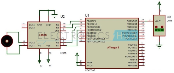
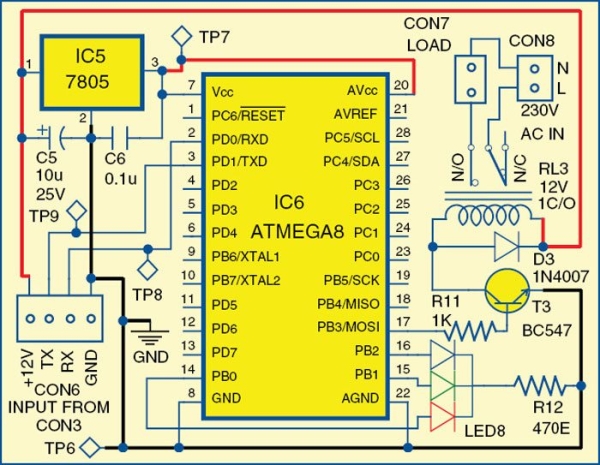
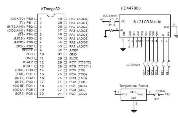
The circuit mainly consists of ATmega8 microcontroller, temperature sensor, DC motor, driver IC. Temperature sensor is connected to the input of the ADC pin i.e. ADC0 pin of the microcontroller.
Temperature sensor has three input pins, VCC, ground. Middle one is output and the other two pins are ground and VCC. VREF and AVCC for the ADC are applied externally to the microcontroller. Pin 20 and 21 are AREF and AVCC pins connected to the supply voltage of 5v.
Port B of the microcontroller is connected to the motors through a motor driver IC i.e. L293D. Input pins of the motor driver are connected to the microcontroller. PB0 and PB1 are connected to the input 3 and input 4 of the motor driver IC.
PB2 and PB3 pins are connected to the input1 and input2 of the motor driver IC. Output pins are connected to the motor. As the motor has two pins, these are connected to the output pins of the driver IC.
Temperature Controlling DC Motor – Circuit Simulation Video
How Temperature Controlled DC Fan Circuit using Microcontroller Works?
Initially switch the power supply.
Microcontroller starts reading the temperature of the surroundings.
The analog value of temperature is given by the temperature sensor.
This analog value is applied to the analog to digital converter pin of the micro controller.
This analog value is converted to the digital value by the microcontroller using successive approximation method internally.
When the temperature is greater than the threshold value, microcontroller sends a command to the controller to switch the motor.
Thus fan starts rotating.
Temperature Controlled DC Motor Project Output Video
Applications
Temperature Controlled DC Fan can be used to control the temperature of devices, rooms, electronic components etc. by monitoring the temperature.
Can be extended to PWM based output, where the speed of the fan can be varied according to the duty cycle of the PWM signal.
The circuit can be used in CPU to reduce the heat.
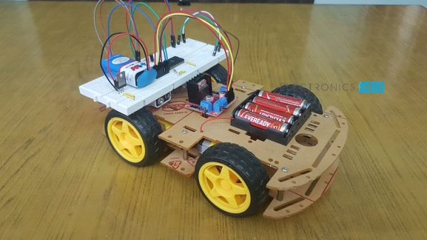
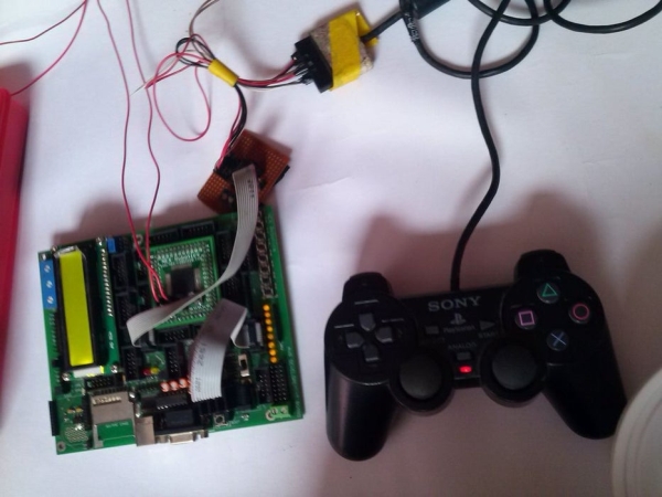
Have you ever made your own robot? Here is a very simple and easy robot. In this project, I will explain how to design and build a Line Follower Robot using microcontroller. The Line Follower Robot is a basic robot that follows a specific path indicated by a line (usually a black line on a light colored surface) having some particular width.
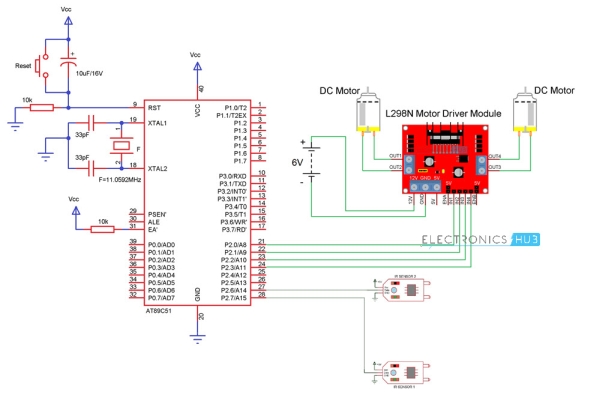
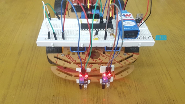
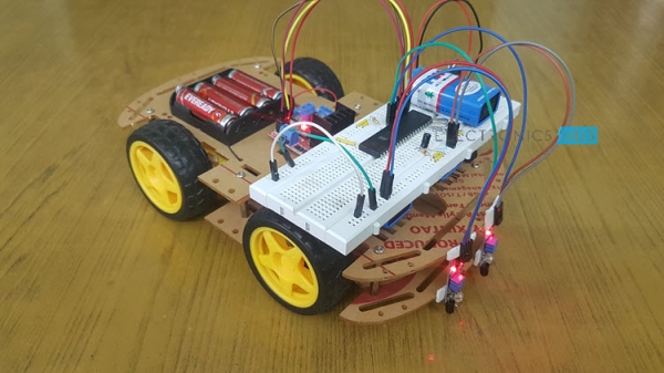
This circuit mainly consists of 8051 microcontroller, two IR sensors, motors and motor driver IC (embedded in a module). The line follower robot needs mechanical arrangement of the chassis. I have used a 4WD Acrylic chassis. The two IR sensors are mounted on the fron of the robot facing with the diodes facing towards Earth.
When robot is placed on the fixed path, it follows the path by detecting the line. The robot direction of motion depends on the two sensors outputs. When the two sensors are on the line of path, robot moves forward. If the left sensor moves away from the line, robot moves towards right. Similarly, if right sensor moves away from the path, robot moves towards its left. Whenever robot moves away from its path it is detected by the IR sensor.
IR sensor consists of IR transmitter and IR receiver on a board. When the vehicle is moving on a black line, IR rays are continuously absorbed by the black surface and there is no reflected ray making output high. Whenever, the robot moves out to the white surface, it starts reflecting the IR rays and making the output low. Thus depending on the output of IR sensor microcontroller indicates the motors to change their direction.
Line Follower Robot Circuit Diagram
Components in the circuit
8051 Microcontroller
Development Board for 8051 Microcontroller (preferred)
10KΩ Resistors X 2
10µF Capacitor
11.0592MHz Crystal
33pF Capacitors X 2
Push Button
Motor driver Module (L298N)
Robot Chassis with Motors
IR Sensors x 2
How to Design a Line Following Robot?
The circuit consists of 8051 microcontroller, IR Sensors (with IR transmitter and IR Receiver), L298N Motor Driver Module, Robot Chassis with 4 wheels and 4 motors, battery holder.
8051 microcontroller is the main component of the project. It is an 8 bit microcontroller with 32 programmable I/O pins. This has many peripheral features like programmable UART, two 8-bit timer/counter, two interrupts, external memory access etc.
The DC motors of the robot are connected to the controller using a motor driver IC. As the output of the controller is maximum 5V with very small current, it cannot drive the motors. So, to amplify this voltage motor driver IC is used. L298N can drive motors up to 36v and can provide a drive current of 3A.
The driver IC has 15 pins and is usually available in multiwatt15 Package. These ICs are easily available in the market as Modules. The inputs to the Motor Driver Module are connected to PORT2 pins P2.0, P2.1, P2.2 and P2.3.
The two IR sensors are connected to P2.6 and P2.7 pins of the microcontroller. Arrange the chassis and connect the four wheels of the robotic vehicle to the motors which are in turn connected to the microcontroller.
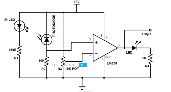
IR sensor circuit consists of mainly IR transmitter and IR receiver. IR transmitter is similar to an LED. Its operating voltage is around 1.4V. So to protect it, a 150Ω resistor is placed in series with it and is connected in forward biased. IR receiver is connected in reverse bias and a 10KΩ resistor is placed between VCC and the receiver. Output is taken between resistor and IR receiver.
Since this is an analog output, we can convert it to a digital HIGH and LOW with the help of a simple comparator IC like LM358, for example. The IR Sensor Module used in this project uses the same configuration and the circuit diagram is shown below.
Working of IR Sensors
The IR transmitter continuously transmits the IR rays. When IR transmitter is on the black surface these rays were absorbed by the surface and when it is on white surface these rays were reflected. The IR receiver has maximum resistance when no IR rays are received and voltage from VCC flows through the resistor. At the output pin, voltage is approximately 5V.
As the intensity IR rays received by the receiver increases, resistance value decreases and reverse break down occurs. Thus voltage through the resistor is grounded. So, at the output pin, it will produce 0V.
Line Following Robotic Vehicle Circuit Working
Initially draw the path on a light colored surface with black color tape.
Place the robot on the floor.
Now power on the circuit.
Robot moves in the specified path.
When it moves out of path, sensors check it and automatically adjust the robot.
Code
#include<reg51.h>
sbit mot1=P2^0;
sbit mot2=P2^1;
sbit mot3=P2^2;
sbit mot4=P2^3;
sbit s_left=P2^6;
sbit s_right=P2^7;
void forward (void);
void backward (void);
void left (void);
void right (void);
void forward (void)
{
mot1=0;
mot2=1;
mot3=1;
mot4=0;
}
void backward (void)
{
mot1=0;
mot2=1;
mot3=0;
mot4=1;
}
void left (void)
{
mot1=0;
mot2=1;
mot3=0;
mot4=0;
}
void right (void)
{
mot1=0;
mot2=0;
mot3=1;
mot4=0;
}
void stop (void)
{
mot1=0;
mot2=0;
mot3=0;
mot4=0;
}
void main()
{
s_left=1;
s_right=1;
while(1)
{
if(s_left==0 && s_right==0)
{
forward();
}
else if(s_left==1 && s_right==1)
{
stop();
}
else if(s_left==0 && s_right==1)
{
left();
}
else if(s_left==1 && s_right==0)
{
right();
}
}
}
Line Following Robot Circuit Applications
This can be used in driver less car system with some added features like obstacle detection.
This can also be used in industrial and defense applications.
Limitations of Line Follower Robot
Line follower robot requires 2-3 inches broad line.
It may not move properly if the black line drawn is of low intensity.
The IR sensors may sometimes absorb IR rays from surroundings also. As a result, robots may move in improper way.
In this era of digital revolution, we are surrounded by smart devices that are capable of making decisions on their own without much human intervention. Our home can also be made smart by implementing a real-time home automation system that monitors parameters like power consumption and human presence. Home automation may include centralised control of electrical devices including lightings, appliances and security.
Presented here is a touch-control based home automation system that can control up to six electrical devices. It also has a separate keyboard interface module for troubleshooting and system settings.
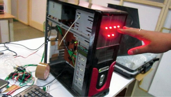
This system consists of closely-networked Atmel’s ATmega8, which is an AVR based microcontroller with 512 bytes EEPROM on a 28-pin DIP package, 1024 bytes internal SRAM and 8kB internal flash memory. The complete system is assembled in a small, portable central processing unit (CPU) chassis for an aesthetic look and uninterrupted 24×7 usage. Author’s prototype is shown in Fig. 1.
Circuit and working
The circuit has four sections: main module, relay module, touch-control module and keyboard interface module. The system is housed on the CPU chassis of a desktop computer and is powered by 400W ATX power supply for error-free operation and proper power delivery to the system.
Advanced Technology eXtended (ATX) is a motherboard form factor specification developed by Intel in 1995 to maintain the integrity and sustainability of the system.
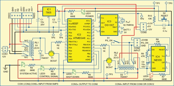
Home automation system: main module
The circuit of the main module is shown in Fig. 2. It has ATmega8 microcontroller, DS1307 RTC chip and NE555 as the main components. The main module controls the load through switching relay RL1.
The system has a standby mode indicator. During standby mode, LED5 glows and power consumption is about 10mW. The ground pin of NE555 timer (IC4) is connected to GND pin of CON2 through relay RL2. LED1 is a power-on indicator and LED2 is a system-active indicator. When RL1 is energised, LED2 glows, indicating that 12V is available from CON1 to CON3 and the complete system is active.
LED3 is a device-control signal indicator that glows momentarily whenever you switch on or switch off a device. LED4 is a shut-down indicator. It glows when a shut-down command is received from the user till the system shuts down completely.
Nowadays, controlling the traffic becomes major issue because of rapid increase in automobiles and also because of large time delays between traffic lights. So, in order to rectify this problem, we will go for density based traffic lights system. This article explains you how to control the traffic based on density.
In this system, we will use IR sensors to measure the traffic density. We have to arrange one IR sensor for each road; these sensors always sense the traffic on that particular road. All these sensors are interfaced to the microcontroller. Based on these sensors, controller detects the traffic and controls the traffic system.
Density Based Traffic Signal System Circuit Principle:
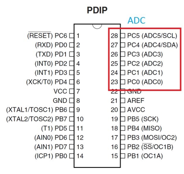
The main heart of this traffic system is microcontroller. IR sensors are connected to the PORT C (PC0, PC1, PC2, and PC3) of the microcontroller and traffic lights are connected to PORT B and PORT D. If there is a traffic on road then that particular sensor output becomes logic 0 otherwise logic 1. By receiving these IR sensor outputs, we have to write the program to control the traffic system.
If you receive logic 0 from any of these sensors, we have to give the green signal to that particular path and give red signal to all other paths. Here continuously we have to monitor the IR sensors to check for the traffic.
Density Based Traffic Signal System Circuit Diagram:
Circuit Components:
ATmega8 controller
PCB board
IR sensors -4
LED’s-12(4-red,4-green,4-yellow)
12v Battery or adaptor
Serial cable
Connecting wires
Density Based Traffic Light Control System Circuit Design:
This circuit consists of 4 IR sensors, atmega8 microcontroller, 4 traffic lights.
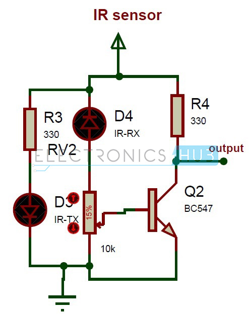
IR transmitter looks like an LED. This IR transmitter always emits IR rays from it. The operating voltage of this IR transmitter is 2 to 3v. These IR (infra red) rays are invisible to the human eye. But we can view these IR rays through camera.
IR receiver receives IR rays that are transmitted by IR transmitter. Normally IR receiver has high resistance in order of mega ohms, when it is receiving IR rays the resistance is very low. The operating voltage of IR receiver also 2 to 3V.
We have to place these IR pair in such a way that when we place an obstacle in front of this IR pair, IR receiver should be able to receive the IR rays. When we give the power, the transmitted IR rays hit the object and reflect back to the IR receiver.
Instead of traffic lights, you can use LEDs (RED, GREEN, YELLOW). In normal traffic system, you have to glow the LEDs on time basis. If the traffic density is high on any particular path, then glows green LED of that particular path and glows the red LEDs for remaining paths.
In normal traffic system, we allow the traffic for a time delay of 1 minute for each path.
The above figure shows the IR sensor circuit. Here 330 ohm resistor is used to drop the voltage otherwise IR transmitter may get damaged. To vary the obstacle sensing distance, we have used a potentiometer. We have taken the ouput from transistor collector. This sensor gives the digital output.
Density based Traffic Signal System Circuit Simulation Video:
How to Operate Density based Traffic Signal System Circuit?
Connect 12V battery or adaptor to the development board.
Switch on the supply.
Burn the program to the ATmega8 microcontroller by keeping the programming switch sw2 in program mode.
Connect four IR sensors to PORT C.
Connect LEDs to PORT B and PORT D.
Arrange all this LED’s same as like traffic lights.
Arrange one IR sensor for each road.
Now you can see the normal traffic system based on time basis.
Now if you place any obstacle in front of any IR sensor, then the system allows the traffic of that particular path by glowing GREEN light.
Finally, turn off the board power supply.
Density based Traffic Signal System Project Output Video:
Limitations of this Circuit:
IR sensors sometimes may absorb normal light also. As a result, traffic system works in improper way.
IR sensors work only for fewer distances.
We have to arrange IR sensors in accurate manner otherwise they may not detect the traffic density.
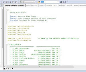
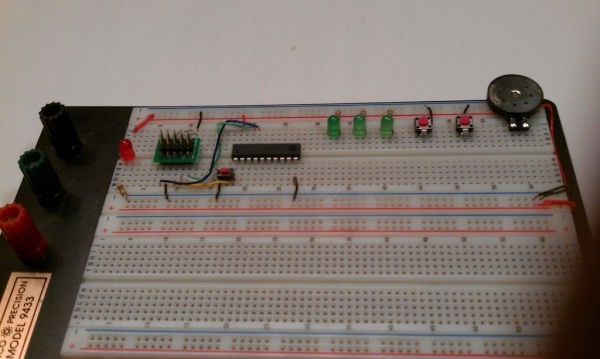
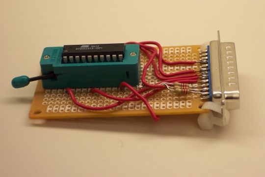
In this section, we will learn How to make program C code for ATMega328PU to toggle the status of the three LED’s according to the input from a button switch. Also, we have explored a solutions to the problem of is ‘Switch Bounce‘. As usually, we will assemble the electrical circuit on base of the AVR ATmega328 to check the work of program code.
Step 1: Writing and Building AVR Microcontroller Application in C Code Using the Integrated Development Platform Atmel Studio 7
If you don’t have Atmel Studio, you should download and install it.
The first few lines we have some compiler defines.
F_CPU defines the clock frequency in Hertz and is common in programs using the avr-libc library. In this case it is used by the delay routines to determine how to calculate time delays.
#include <avr/io.h> // header to enable data flow control over pins. Defines pins, ports, etc.
The first include file is part of avr-libc and will be used in pretty much any AVR project you work on. io.h will determine the CPU you’re using (which is why you specify the part when compiling) and in turn include the appropriate IO definition header for the chip we’re using. It simply defines the constants for all your pins, ports, special registers, etc.
#include <util/delay.h> // header to enable delay function in program
The library util/delay.h contains some routines for short delays. The function we’ll be using, is _delay_ms().
We use defines to declare our button and LED’s ports and pins. Using the defines statements like this allows us to only need to modify 3 easy-to-find lines if we move the LED to a different I/O pin or use a different AVR.
#define BUTTON1 1 // button switch connected to port B pin 1
#define LED1 0 // Led1 connected to port B pin 0
#define LED2 1 // Led2 connected to port C pin 1
#define LED3 2 // Led3 connected to port D pin 2
The final two define statements setup times, in millisecond, to debounce the switch and the time to wait before allowing another press of the button. The debounce time needs to be adjusted to the time it takes the switch to go from a digital high to a digital low after all the bouncing. The bounce behavior will differ from switch to switch, but 20-30 milliseconds is typically quite sufficient.
#define DEBOUNCE_TIME 25 // time to wait while "de-bouncing" button
#define LOCK_INPUT_TIME 300 // time to wait after a button press
void init_ports_mcu()
{
This function is called just once in the beginning of our program to initialize input output pins that we will be using.
For the button, we will be using the PORT and PIN registers for writing and reading. With AVRs, we read a pin using it’s PINx register and we write to a pin using it’s PORTx register. We need to write to the button register to enable the pull-ups.
For the LED we only need to use the PORT register to write to, however, we also need the data direction register (DDR) as the I/O pins are setup as inputs by default.
First, we’re setting the LED’s I/O pins as an output using it’s data direction register.
DDRB=0xFFu; // Set all pins of the PORTB as output.
Next, explicitly set the button pin as an input.
DDRB &= ~(1<<BUTTON1); // Makes first pin of PORTB as Input
Next, the PORTB pins is set high (+5 volt) to turn it on. The output pins is initially high, and since our LED is wired active-high, it will be turned on unless we explicitly turn it off.
And finally, we enable the internal pull-up resistor on the input pin we’re using for our button. This is done simply by outputting a one to the port. When configured as an input, doing so results in enabling pull-ups and when configured as an output, doing so would simply output a high voltage.
PORTB = 0xFF; // Set all pins of the PORTB as HIGH. Led is turn on,
// also the internal Pull Up resistor of first pin PORTB is enable.
DDRC=0xFFu; // Set all pins of the PORTC as output.
PORTC=0x00u; // Set all pins of PORTC low which turns it off.
DDRD=0xFFu; // Set all pins of the PORTD as output.
PORTD=0x00u; // Set all pins of PORTD low which turns it off.
}
unsigned char button_state()
{
This function returns a boolean value indicating whether or not the button was pressed. This is the block of code with is continually being executed in the infinate loop and thus is polling the state of the button. This is also where we debounce the switch.
Now, remember that when we press the switch, the input output pin is pulled to ground. Thus, we’re waiting for the pin to go low.
/* the button is pressed when BUTTON1 bit is clear */
if (!(PINB & (1<<BUTTON1))) {
We do so by checking if the bit is clear. If the bit is clear, indicating that the button is depressed, we first delay for the amount of time defined by DEBOUNCE_TIME which is 25ms and then check the state of the button again. If the button is depressed after the 25ms then the switch is considered to be debounced and ready to trigger an event and so we return 1 to our calling routine. If the button is not depressed, we return 0 to our calling routine.
Our main routine. The main function is unique and set apart from all other functions. Every C program must have exactly one main() function. main is where the AVR starts executing your code when the power first goes on, so it’s the entry point of the program.
unsigned char n_led = 1; // initially LED number is on now<br>
Call of the function to initialize I/O pins being used:
init_ports_mcu();
infinite loop where our program runs:
while (1)
{
When button_state returns one indicating that the button was pressed and debounced, then toggling the current status of LED’s in turn according to the n_led parameter.
if (button_state()) // If the button is pressed, toggle the LED's state and delay for 300ms (#define LOCK_INPUT_TIME)
{
switch(n_led){
case 1:
PORTB ^= (1<<LED1);
PORTC ^= (1<<LED2);
break;
These statements uses C bitwise operators. This time it’s using the exclusive OR operator. When you XOR the PORT with the bit value of the bit you want to toggle, that one bit is changed without effecting the other bits.
case 2:
PORTC ^= (1<<LED2);<br> PORTD ^= (1<<LED3);
break;
case 3:
PORTD ^= (1<<LED3);
PORTB ^= (1<<LED1);
n_led=0; // reset LED number
break;
}
n_led++; // next LED is turn on
_delay_ms(LOCK_INPUT_TIME);
}
}
return (0);
}
So now, when you run this program, you should be able to press the push-button to LED’s are toggling. Due to our delay defined by LOCK_INPUT_TIME, you can press and hold the button which will cause the LED’s to turn off and on at a consistant rate (little more than every 275ms).
Programming is complete.
Next step is building the project and programming hex file into the microcontroller using the avrdude program.
You can download main.c file with program in c code:
Step 2: Transfering the HEX File of Program Into the Flash Memory of Chip
Download and install AVRDUDE. The latest version available is 6.3: Download the zip file
First, copy the hex file of program in to AVRDUDE directory. In my case it is ButtonAVR.hex
Then, type in DOS prompt window the command: avrdude –c [name of programmer] –p m328p –u –U flash:w:[name of your hex file].
In my case it is: avrdude –c ISPProgv1 –p m328p –u –U flash:w:ButtonAVR.hex
This command writes hex file to the microcontroller’s memory.
Watch the video with a detailed description of the microcontroller flash memory burning:
Ok! Now, the microcontroller works in accordance with the instructions of our program. Let’s check it out!
Step 3: Hardware Switch Debouncing
In addition to Software switch debouncing we can use hardware switch debouncing technique. The basic idea behind such technique is to use a capacitor to filter out quick changes in the switch signal.
What value capacitor should be select? This will ultimately depend on how poorly the button performs regarding this particular problem. Some buttons can display a tremendous bouncing behavior, yet others will have very little. A low capacitor value like 1.0 nanofarads will react very quickly, with little or no effect on the bouncing. Conversely, a higher capacitor value such as 220 nanofarads (which is still pretty small in terms of capacitors) will provide a slow transition from the starting to the ending voltage (5 volt to 0 volt). The transition seen with a 220 nanofarads capacity is still pretty fast in a real-world sense however, and thus can be used on poorly performing buttons.
In this case we will create simple program in C code and burn it into the memory of the microcontroller. We will write our own program and compile the hex file, using the Atmel Studio as the integrated development platform. We will configure fuse bits and upload hex file into the memory of the AVR ATMega328P microcontroller, using our own programmer and software AVRDUDE.
AVRDUDE – is a program for downloading and uploading the on-chip memories of Atmel’s AVR microcontrollers. It can program the Flash and EEPROM, and where supported by the serial programming protocol, it can program fuse and lock bits.
Step 1: Writing Program and Compile the Hex File, Using the Atmel Studio
This project will use C, so select the GCC C Executable Project option from the template list to generate a bare-bones executable project.
Next, it is necessary to specify which device the project will be developed for. This project will be developed for the AVR ATMega328P microcontroller.
Type the code of program in the Main Source Editor area of Atmel Studio. The Main Source Editor – This window is the main editor for the source files in the current project. The editor has spell check and auto complete features.
1. We must tell compiler at what speed our chip is running to that it can calculate delays properly.
2. We include the preamble, which is where we put our include information from other files, which defines global variables and functions.
#include <avr/io.h> //header to enable data flow control over pins. Defines pins, ports, etc.
#include <util/delay.h> //header to enable delay function in program
3. After the preamble comes the main() function.
int main(void) {
The main() function is unique and set apart from all other functions. Every C program must have exactly one main() function. Main() is where the AVR starts executing your code when the power first goes on, so it’s the entry point of the program.
4.Set pin 0 of the PORTB as output.
DDRB=0b00000001; //Set PORTB1 as output
We do this by writing a binary number to the Data Direction Register B. The Data Direction Register B allows us to make the bits of register B input or output. Writing a 1 makes them output, while a 0 would make them input. Being that we are attaching an LED to act as output, we write a binary number, making the pin 0 of PORT B as output.
5. Loop.
while (1) {
This statement is a loop, often referred to as the main loop or event loop. This code is always true; therefore, it executes over and over again in an infinite loop. It never ceases. Therefore, LED will be blinking in an infinity, unless power is shut off from the microcontroller or the code is erased from program memory.
6. Turn on LED attached to port PB0
PORTB= 0b00000001; //turns on LED attached to port PB0
This line, gives a 1 to the PB0 of PortB. PORTB is a hardware register on the AVR chip that contains 8 pins, PB7-PB0, going from left to right. Putting a 1 at the end gives a 1 to PB0; this sets PB0 high which turns it on. Therefore, the LED attached to pin PB0 will turn on and light up.
7. Delay
_delay_ms(1000); //creates a 1-second delay
This statement create a 1-second delay, so that the LED turns and stays on for exactly 1 second.
8. Turn off all B pins, including PB0
PORTB= 0b00000000; //Turns off all B pins, including PB0
This line turns off all 8 Port B pins, so that even PB0 is off, so the LED turns off.
9. Another delay
_delay_ms(1000); //creates another 1-second delay
It turns off exactly for 1 second, before starting the loop all over again and encountering the line, which turns it back on, repeating the process all over. This happens infinitely so that the LED constantly blinks on and off.
10. Return statement
}
return (0); //this line is never actually reached
}
The last line of our code is a return(0) statement. Even though this code is never executed, because there is an infinite loop which never ends, for our programs that run on desktop computers, it’s important for the operating system to know whether they ran correctly or not. For that reason, GCC, our compiler, wants every main() to end with a return code. Return codes are needless for AVR code, which runs freestanding of any supporting operating system; nevertheless, the compiler will raise a warning if you don’t end main with return().
The final step is the building the project. It means compiling and finally linking all object files to generate the executable file (.hex) file. This hex file is generated inside the folder Debug which is inside the Project folder. This hex file is ready to be loaded into the microcontroller chip.
Step 2: Changing the Default Configuration of the Micro Controller Fuse Bits
It is important to remember that some of the fuse bits can be used to lock certain aspects of the chip and can potentially brick it (make it unusable).
There are a total of 19 fuse bits that are used in the ATmega328P, and they are separated into three different fuse bytes. Three of the fuse bits are contained in the “Extended Fuse Byte”, eight are contained in the “Fuse High Byte,” and eight more are contained in the “Fuse Low Byte”. There is also a forth byte that is used to program the lock bits.
Each byte is 8 bits and each bit is a separate setting or flag. When we talk about setting, not setting, programmed, not programmed fuses we are actually using binary. 1 means not set, not programmed and a zero means set, programmed. When programming the fuses you can use binary notation or more commonly hexadecimal notation.
ATmega 328P chips have a built in RC oscillator which has a 8 MHz frequency. New chips are shipped with this set as the clock source and the CKDIV8 fuse active, resulting in a 1 MHz system clock. The startup time is set to maximum and time-out period enabled.
New ATMega 328P chips generally have the following fuse settings:
Low fuse = 0x62 (0b01100010)
High fuse = 0xD9 (0b11011001)
Extended fuse = 0xFF (0b11111111)
We will be use ATmega 328 chip with an external 16MHz crystal. Therefore, we need to program bits of “Fuse Low Byte” accordingly.
1. Bits 3-0 control the oscillator choice, and the default setting of 0010 is to use the calibrated internal RC oscillator, which we don’t want. We want the low power crystal oscillator operation from 8.0 to 16.0 MHz, so bits 3-1 (CKSEL[3:1]) should be set to 111.
2.Bits 5 and 4 control the startup time, and the default setting of 10 is for a startup delay of six clock cycles from power-down and power-save, plus an additional startup delay of 14 clock cycles plus 65 milliseconds from reset.
To be on the safe side for a low power crystal oscillator, we want the maximum delay possible of 16,000 clock cycles from power-down and power-save, so SUT[1] should be set to 1, plus an additional startup delay of 14 clock cycles plus 65 milliseconds from reset, so SUT[0] should be set to 1. In addition, CKSEL[0] should be set to 1.
3. Bit 6 controls the clock output to PORTB0, which we don’t care about. So, bit 6 can be left set to 1.
4. Bit 7 controls the divide-by-8 operation and the default setting of 0 has the feature enabled, which we don’t want. So, bit 7 needs to be changed from 0 to 1.
Therefore, the new Fuse Low Byte should be 11111111 which, in hexadecimal notation, is 0xFF.
To program bits of the “Fuse Low Byte” we can use our programmer (https://www.instructables.com/id/ISP-Programmer-fo…) and software AVRDUDE. AVRDUDE is a command-line utility that is used to download from and upload to Atmel microcontrollers.
First, we must add describe our programmer to the configuration file of AVRDUDE. On Windows the configuration file is usally in the same location as the executable file of AVRDUDE.
Pastе the text in configuration file avrdude.conf:
Before starting the AVRDUDE, we must connect the microcontroller to the programmer, according to the scheme.
Open DOS prompt window.
1. To view the list of programmer that avrdude is supported type command avrdude -c c. If all is well, the list should have programmer id “ISPProgv1”
2. To view the list of Atmel devices that avrdude is supported type command avrdude -c ISPProgv1. The list should have device m328p for Atmel ATMega 328P.
Next, type avrdude -c ISPProgv1 –p m328p,the command tell avrdude what programmer is being used and what Atmel microcontroller is attached. It presents the ATmega328P signature in hexadecimal notation: 0x1e950f. It presents the fuse bit programming currently in the ATmega328P also in hexadecimal notation; in this case, fuse bytes are programmed per factory default.
Next, type avrdude -c ISPProgv1 –p m328p –U lfuse:w:0xFF:m, It is a command to tell avrdude what programmer is being used and what Atmel microcontroller is attached and to change the Fuse Low Byte to 0xFF.
Now the clock signal should come from low power crystal oscillator.
Step 3: Burning the Program Into the Memory of the ATMega328P Microcontroller
First, copy the hex file of program we made at the beginning of the instruction in to AVRDUDE directory.
Then, type in DOS prompt window the command avrdude –c ISPProgv1 –p m328p –u –U flash:w:[name of your hex file]
The command writes hex file to the microcontroller’s memory. Now, the microcontroller works in accordance with the instructions of our program. Let’s check it out!
Step 4: Check Microcontroller Works in Accordance With the Instructions of Our Program
Connect components in accordance with schematic diagram of the AVR Blinking LED Circuit.
First, we need power, as all AVR circuits do. About 5 volts of power is sufficient for operation of the AVR chip. You can get this either from batteries or a DC power supply. We connect +5V of power to pin 7 and connect pin 8 to ground on the breadboard. In between both pins, we place a 0.1μF ceramic capacitor to smooth out the power of the power supply so that the AVR chip gets a smooth power line.
The 10KΩ resistor is used to provide Power On Reset (POR) to the device. When the power is switched ON, voltage across capacitor will be zero so the device resets (since reset is active low), then the capacitor charges to VCC and the reset will be disabled.
We connect the anode of our LED to AVR pin PB0. This is pin 14 of the ATMega328P. Since it is an LED, we want to limit current flowing to the LED so it doesn’t burn out. This is why we place a 330Ω resistor in series with the LED. The cathode of the LED gets connected to ground.
16 MHz crystal is used to provide clock for the Atmega328 microcontroller and 22pF capacitors are used to stabilize the operation of crystal.
These are all the connections necessary to light up the LED. Power supply.
Ok. LED is blinking with one-second delay. The work of the microcontroller corresponds to our tasks.
Step 5: Conclusion
Admittedly, that was a long process for just flashing an LED, but the truth is that you have successfully cleared major hurdles: creating a hardware platform for programming an AVR microcontroller, Using the Atmel Studio as the integrated development platform, using AVRDUDE as software for configuring and programming an AVR microcontroller.
If you want to keep up to date on my base microcontrollers projects, subscribe to my YouTube! Watching and sharing my videos is way to support what I do.
Atmel Studio is a powerful tool for making AVR programs, but writing a program is the first step. To use your program, you must make a circuit and transfer your code into the microcontroller. You can program your AVR from Atmel Studio by the use of STK500 hardware. Why you cannot program MCU directly from computer by cheap hardware like PIC microcontrollers? The answer is that to transfer your program to IC you must use SPI connection, but there is no SPI port on the PC. There is plenty of software that uses RS232 port as SPI, but you cannot program your AVR directly from Atmel Studio like them. Here I introduce you software that simulates STK500 hardware on the PC and sends data to the microcontroller using RS232 via simple and cheap hardware. Note that using PC RS232 as SPI port is slow and programming the chip will take more time than an STK500 device.
Step 1: Making the Hardware
To make the hardware you need:
About 1 meter cable with 5 wires or more
DB9 female connector
Pin header
3x 4.7K resistors
3x 5.1V Zener diodes
Soldering tools
Solder resistors to pins 3, 4, 6 and 7 of DB9 connector, solder N pin of diodes to the other end of resistors and solder the other leg of diodes to the pin 5 of DB9 connector. Solder cable wires between resistors and diodes and pins 4 and 5 of DB9 connector. Solder the other end of cable wires to the female part of Pin header.
Looking at the circuit diagram will help you a lot while making the hardware.
Note that RESET pin of microcontroller must be connected to +5V via a 10K resistor in your circuit if there is no pull-up resistor in the microcontroller itself.
Step 2: Virtual Ports
Before using WinSTK500 software you need a pair of virtual serial ports. There is a lot of virtual serial port emulator software like Virtual Serial Ports Emulator, com0com (mirror) and etc. Here I used com0com software. After installing com0com, create a pair of virtual serial ports like ones on the picture.
If you want to access WinSTK500 easily, run Atmel Studio and from the Tools menu select External Tools…, add a new tool, set the title to WinSTK500, select [Install Location]\dihav\WinSTK500\WinSTK500.exe as the command and click OK. Now you can find WinSTK500 on the Tools menu.
Step 4: Connecting to WinSTK500
Connect your MCU to the hardware and connect it to RS232 serial port. Run Atmel studio, select WinSTK500 from Tools menu, select CNCB0 as STK port, select your computer serial port (usually COM1) as SPI port and click Start button. Click on Add target… from Tools menu and add an STK500 tool at CNCA0 port. Choose Device Programming from Tools menu, select STK500 CNCA0 from Tool drop down menu, choose your microcontroller and use ISP interface, then click Apply button. The Atmel Studio will be connected to WinSTK500.
Step 5: WinSTK500 Settings
After connecting to WinSTK500, you can see 3 items related to the tool at the top of the items located on the left panel of Device Programming window.
You can change SPI clock frequency on the Interface settings, but note that WinSTK500 is a slow device and only supports 10-25 KHz, the default frequency is about 16 KHz that is recommended not to change it.
Tool information is just some info about the tool.
The Board settings are just some variables that do not affect WinSTK500.
There are also two options on the WinSTK500 window:
Command Failure Reset defines the behavior of the WinSTK500 when the command does not execute and is usually set to SCK Pin. If you tried programming several times and you faced timeout error and all connections are OK, try changing this option. You can also find some info about this option on your microcontroller datasheet.
If after connecting to WinSTK500, Atmel Studio said that the STK firmware must be upgraded increase the Software Version to avoid this message.
Step 6: Programming Your Microcontroller
After connecting your microcontroller to Atmel Studio via WinSTK500 you can program it from Device Programming window. Note that after programming the RESET pin will not become high, so to run the program the programming cable must be disconnected.
Step 7: Can WinSTK500 Program AT89?
The difference between programming AVR and AT89 is the RESET pin polarity. So you must use another hardware that I have placed its circuit diagram here. I have not tested it myself, but it must work correctly. If you made it and it worked well tell me and the other readers in the comments.
I have seen plenty of Instructables showing how to work with microprocessors, but they all assume that you have worked with them before and know what you are doing. I have not seen an Instructable that takes you from nothing and builds on each step.
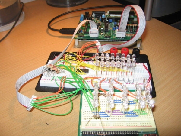
What we will do here is to start with a bare breadboard and build each connection and each component until we have everything we need to program a microcontroller to do something. In this Instructable we will blink some LEDs in sequence… then if you build this circuit… your first project can be to change the code slightly to make it into a traffic light.
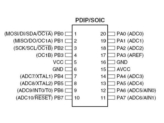
I picked an older Atmel chip, the Tiny-26 to get started. It is a smaller microprocessor, very inexpensive, and easy to understand. Once you understand what we are doing here, you may want to try a more powerful chip like the Mega-328P which has more pins and more memory.
Note: The Tiny-261, Tiny-461, and Tiny-861 are pin compatible newer versions of the Tiny-26. They have 2K, 4K, and 8K of memory. If used, simply change the header by selecting the appropriate chip and recompile the program to use the newer version. The new chips have more functions that can be assigned to each pin. See the datasheets for more details. Tiny 261, 461, 861 Datasheet (PDF) Tiny 26Datasheet (PDF)
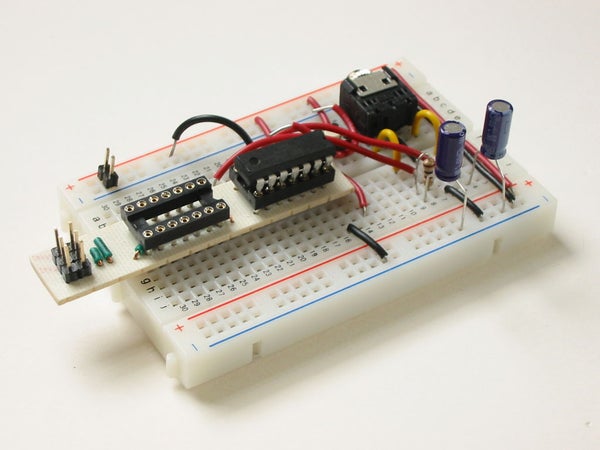
Below is an image with the pins for the chip we will be using… we will be connecting the power and ground… in this case 5v. So where do we get 5 volts? We will build a power supply from a 9v battery.
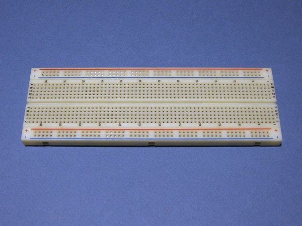
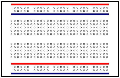
Below you can see a breadboard… they come in many sizes depending on how complex the circuit you want to build will be. We will use a medium sized breadboard with enough room for our power supply, the microprocessor, and the LEDs we want to control.
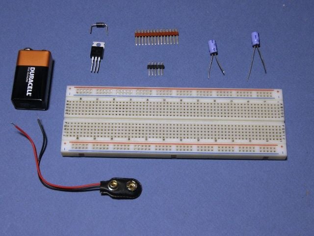
Step 2: Starting With the Power Supply
We will use a voltage regulator called a 7805. It has three pins, the first is the input, next is the ground, and last is the output voltage… in this case 5 volts. The chip needs to have greater than 6 volts to be able to regulate it down to 5 volts… but it cannot have more than 36 volts. The 9 volt battery works well in this application.
We also want to install a diode into the circuit… it will allow current to flow in only one direction. The reason we install it is so that if we connect the battery backwards it will not let the current flow and will protect our circuit from damage. The diode has a line printed on it, this should be on the most negative side, in our case… it connects to the input of the voltage regulator.
The 9 volt battery clip uses stranded wires… they do not plug into a breadboard very well so we need to make it so that we can install the connections properly. We will use what is called a SIP header. (Single Inline Pins) The wires are soldered to the pins and then can be inserted into the breadboard.
If you look at image #3, you can see that the wires are soldered to TWO pins. This is done to provide a stronger connection that won’t turn or jiggle loose. (It’s a good tip to remember! )
We insert the pins into the breadboard and install the diode. (Image #4)
In Image #5 you can see that we have added a capacitor… it is a 47uF rated at least 6 volts… these are 25 volts… so they are fine. They act to smooth out the voltage when things like LEDs turn on and off. One way to think of them is like the water tank in your toilet… when you flush you need a large flow of water all at once… but the supply line is very small. The tank holds enough water to even out the flow. Likewise, the capacitor holds extra power for when there is a surge from things starting and stopping.
One capacitor goes between the input to the voltage regulator and the ground, the other goes between the ground and the regulated 5 volts. The capacitor has a marking to show which side connects to ground.
In Image #6 and Image #7 you can see the completed power supply.
Step 3: Wires and Connections
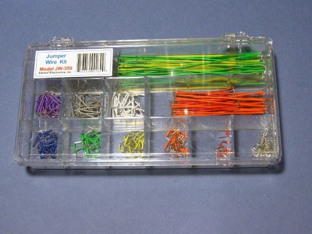
You will notice that my connections to the board are very neat and easy to follow. (At least I hope so!) I am using a wire kit that is available online from several places. The kits are about $10 to $20 depending where you look… and refills are available from places like Digikey .
The kits make your wire connections short, clean, and easy to follow when you come back to them in the future. The refills are a bit pricey, but if you get into electronics quite a bit you will find that you don’t want to live without them.
A great way to get started is to find some 22 gauge to 24 gauge SOLID wire. You don’t want stranded wires in a breadboard… they just don’t work well. Solid wire is useful when you want it stiff and bendable as we are doing here. Stranded wire is used when it must be flexible.
If you see the local telephone repair person ask if they have any scrap 25 pair cable. They often get it in 500 foot rolls… and if it has less than 20 or so feet will often throw it away. The cable has a string that when pulled will cut the jacket and give you a whole bunch of wires as shown in Image #3 .
Step 4: How Do We Know If It’s Working???
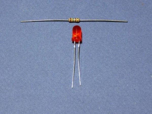
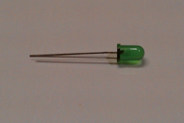
So now we have a power supply for the microprocessor and out LEDs. But how do we know if it is working? We can install an LED so that when the power supply is on it will illuminate. This is also a good time to teach you about resistors. We will be working with 5 volts… but an LED is designed to run on only 2 volts. (Approximate, they vary depending on the type. )
If we were to connect a 2v LED to the 5v supply, it would get very bright for a very short period of time… then POOF! Here is where you need a little math… don’t worry… it’s not too bad.
If we look at the specification sheet for the LED, it says that it runs on 2 volts at 20mA. Okay… let’s start with the voltage… 5 volts minus 2 volts is 3 volts. So we have 3 volts too much for the LED. (Told you the math wasn’t too hard.)
Okay… the LED runs on 20mA… that’s the same as 0.020 amps. (mA are 1/1000 of an amp… so 1000mA = 1A) We know that we have 3 volts too much… so divide that by the current that the LED is supposed to run at… 3 divided by 0.020 = 150.
So we know that we need to have a resistance of 150 ohms to slow down the flow of electricity to a point where it won’t burn out the led. Voltage / Current = Ohms.
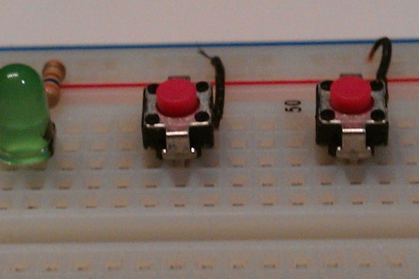
We install our resistor (150 ohms) and our LED onto the board… now we know if we have power or not!
In thid tutorial you will know everything ADC in avr microcontroller
Step 1: What Is an ADC?
An ADC, or Analog to Digital Converter, allows one to convert an analog voltage to a digital value that can be used by a microcontroller. There are many sources of analog signals that one might like to measure. There are analog sensors available that measure temperature, light intensity, distance, position, and force, just to name a few.
Step 2: How Work ADC in AVR- Microcontroller
The AVR ADC allows the AVR microcontroller to convert analog voltages to digital values with few to no external parts. The ATmega8 features a 10-bit successive approximation ADC.ATmega8 has 7 channel ADC at PortC. The ADC has a separate analog supply voltage pin, AVCC. AVCC must not differ more than ± 0.3V from VCC.. The voltage reference may be externally decoupled at the AREF pin. AVCC is used as the voltage reference. The ADC can also be set to run continuously (the free-running mode) or to do only one conversion.
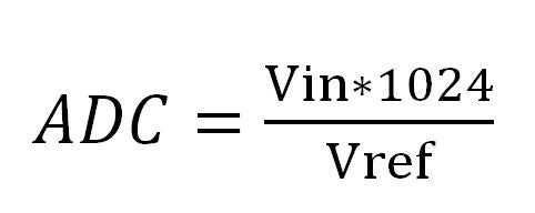
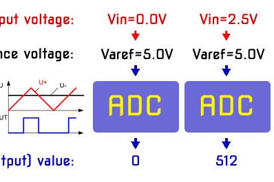
Step 3: ADC Conversion Formula
Where Vin is the voltage on the selected input pin and Vref the selected voltage reference
Step 4: How to Configure ADC in ATmega8?
The following Registers are used for implementation of ADC in ATmega8
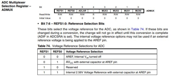
ADC Multiplexer Selection
Step 5: ADLAR Selection
ADC Left Adjust Result The ADLAR bit affects the presentation of the ADC conversion result in the ADC Data Register. Write one to ADLAR to left adjust the result. Otherwise, the result is right adjusted
When an ADC conversion is complete, the result is found in ADCH and ADCL When ADCL is read, the ADC Data Register is not updated until ADCH is read. Consequently, if the result is left adjusted and no more than 8-bit precision is required, it is sufficient to read ADCH. Otherwise, ADCL must be read first, then ADCH. Analog Channel Selection Bits The value of these bits selects which analog inputs are connected to the ADC.
Step 6: ADCSRA Selection
• Bit 7 – ADEN: ADC Enable Writing this bit to one enables the ADC. By writing it to zero, the ADC is turned off
• Bit 6 – ADSC: ADC Start Conversion In Single Conversion mode, write this bit to one to start each conversion. In Free Running mode, write this bit to one to start the first conversion.
• Bit 5 – ADFR: ADC Free Running Select When this bit is set (one) the ADC operates in Free Running mode. In this mode, the ADC samples and updates the Data Registers continuously. Clearing this bit (zero) will Terminate Free Running mode.
• Bit 4 – ADIF: ADC Interrupt Flag This bit is set when an ADC conversion completes and the Data Registers are updated. The ADC Conversion Complete Interrupt is executed if the ADIE bit and the I-bit in SREG are set. ADIF is cleared by hardware when executing the corresponding interrupt Handling Vector. Alternatively, ADIF is cleared by writing a logical one to the flag.
• Bit 3 – ADIE: ADC Interrupt Enable When this bit is written to one and the I-bit in SREG is set, the ADC Conversion Complete Interrupt is activated.
• Bits 2:0 – ADPS2:0: ADC Prescaler Select Bits According to the datasheet, this prescalar needs to be set so that the ADC input frequency is between 50 KHz and 200 KHz. The ADC clock is derived from the system clock with help of ADPS2:0 These bits determine the division factor between the XTAL frequency and the input clock to the ADC.
Pulse Width Modulation (PWM) is a very common technique in telecommunication and power control. it is commonly used to control the power fed to an electrical device, whether it is a motor, an LED, speakers, etc. It is basically a modulationtechnique, in which the width of the carrier pulse is varied in accordance with the analog message signal.
We make simple electrical circuit to control rotational speed of the DC motor in light intensity dependent. We are going to use Light Dependent Resistor and AVR microcontroller features such as Analog to Digital Conversion to measure the light intensity. Also we are going to use Dual H-Bridge Motor Driver Module-L298N. It is typically used in controlling motors speed and direction, but can be used for other projects such as driving the brightness of certain lighting projects. Also, added a button to our circuit to toggle the direction of rotation of the engine.
Step 1: Description
Each and every body in this world has some inertia. The motor rotates whenever it is powered on. As soon as it is powered off, it will tend to stop. But it doesn’t stop immediately, it takes some time. But before it stops completely, it is powered on again! Thus it starts to move. But even now, it takes some time to reach its full speed. But before it happens, it is powered off, and so on. Thus, the overall effect of this action is that the motor rotates continuously, but at a lower speed.
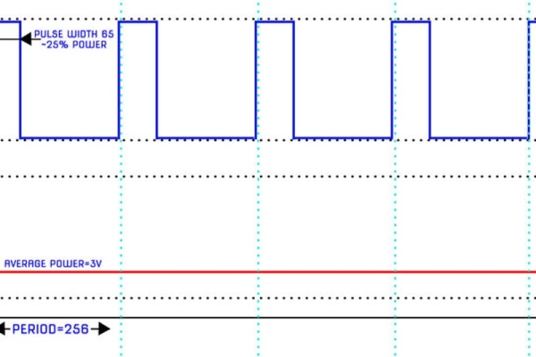
Pulse Width Modulation (PWM) is a comparatively recent power switching technique for providing intermediate amounts of electrical power between fully on and fully off levels. Usually, digital pulses have same on and off time period, but in some situations we need the digital pulse to have more/less on time/offtime. In PWM technique, we create digital pulses with unequal amount of on and off state to get required intermediate voltage values.
Duty cycle is defined by the percentage of high voltage duration in a complete digital pulse. It can be calculated by:
% of Duty cycle = T on /T (period time) x 100
Let us take a problem statement. We need to generate a 50 Hz PWM signal having 45% duty cycle.
Frequency = 50 Hz
Time period, T = T(on) + T(off) = 1/50 = 0.02 s = 20 ms
Duty Cycle = 45%
Thus, solving according to equation given above, we get
T(on) = 9 ms
T(off) = 11 ms
Step 2: AVR Timers – PWM Mode
For making PWM, AVR contains separate hardware! By using this, the CPU instructs the hardware to produce PWM of a particular duty cycle. The ATmega328 has 6 PWM outputs, 2 are located on timer/counter0 (8bit), 2 are located on timer/counter1 (16bit), and 2 is located on timer/counter2 (8bit). Timer/Counter0 is the simplest PWM device on the ATmega328. Timer/Counter0 is capable of running on 3 modes:
Fast PWM
Phase and Frequency Corrected PWM
Phase Corrected PWM
each of these modes can be inverted or non-inverted.
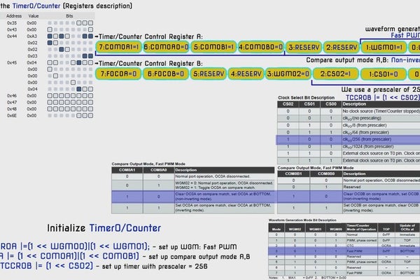
Initialize Timer0 in PWM mode:
TCCR0A |=(1 << WGM00)|(1 << WGM01) – set up WGM: Fast PWM
TCCR0A |= (1 << COM0A1)|(1 << COM0B1) – set up compare output mode A,B
TCCR0B |= (1 << CS02) – set up timer with prescaler = 256
Step 3: Light Intensity Measurement – ADC & LDR.
Light Dependent Resistor (LDR) is a transducer which changes its resistance when light falls on its surface changes.
LDRs are made from semiconductor materials to enable them to have their light sensitive properties. These LDRs or PHOTO RESISTORS work on the principle of “Photo Conductivity”. Now what this principle says is whenever light falls on the surface of the LDR (in this case) the conductance of the element increases or in other words the resistance of the LDR decreases when the light falls on the surface of the LDR. This property of the decrease in resistance for the LDR is achieved because it is a property of semiconductor material used on the surface. LDR are used most of times to detect presence of light or for measuring the intensity of light.
For transferring external continuous information (analog information) into a digital/computing system, we must convert them into integer (digital) values. This type of conversion is carried out by Analog to Digital Converter (ADC). The process of converting an analog value into digital value is known as Analog to Digital Conversion. In short, Analog signals are real world signals around us like sound and light.
Digital signals are analog equivalents in digital or numeric format which are well understood by digital systems like microcontrollers. ADC is one such hardware which measures analog signals and produces a digital equivalent of the same signal. AVR microcontrollers has inbuilt ADC facility to convert analog voltage into an integer. AVR convert it into 10-bit number of range 0 to 1023.
We use analog to digital convert of voltage level from divider circuit with LDR to measure the light intensity.
Initialize ADC:
TADCSRA |= (1<<ADEN) – Enable ADC
ADCSRA |= (1<<ADPS2)| (1<<ADPS1)| (1ADPS0) – set up ADC prescaler = 128
ADMUX = (1 << REFS0) – set up voltage referance = AVCC; – set up Input Channel = ADC0
Step 4: Controller DC Motor & Dual H-Bridge Motor Driver Module-L298N
We use DC motor drivers because microcontrollers are not capable of delivering current not more than 100 milliamps in general. The microcontrollers are smart but not strong; this module will add some muscles to microcontrollers to drive high power DC motors. It can control 2 DC motors simultaneously up to 2 amps each or one stepper motor. We can control the speed using PWM and also its rotational direction of the motors. Also, It used for driving the brightness of LED tape.
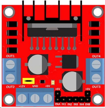
Pin description:
OUT1 and OUT2 port, which is for connecting DC motor. OUT3 and OUT4 for connecting LED tape.
ENA and ENB are enable pins: by connecting ENA to high(+5V) it enables the port OUT1 and OUT2.
If you connect the ENA pin to low(GND), it disables the OUT1 and OUT2. Similarly, for ENB and OUT3 and OUT4.
IN1 to IN4 are the input pins which will be connected to AVR.
If IN1-high(+5V), IN2-low(GND), the OUT1 turns high and OUT2 turns low, thus we can drive motor.
If IN3-high(+5V), IN4-low(GND), the OUT4 turns high and OUT3 turns low, thus LED tape light is on.
If you want to reverse the rotational direction of the motor just reverse IN1 and IN2 polarity, similarly for IN3 and IN4.
By applying PWM signal to ENA and ENB you can control the speed of the motors on two different output ports.
The board can accept from 7V to 12V nominally.
Jumpers:There are three jumper pins; Jumper 1: If you’re motor need more than 12V supply you have to disconnect the Jumper 1 and apply desired voltage (max 35V) at 12V terminal. Bring another 5V supply and input at 5V terminal. Yes, you have to input 5V if you need to apply more than 12V (when Jumper 1 is removed).
The 5V input is for proper functioning of the IC, since removing the jumper will disable the in-built 5V regulator and protect from higher input voltage from 12V terminal.
The 5V terminal acts as output if your supply is between 7V to 12V and acts as input if you apply more than 12V and jumper is removed.
Jumper 2 and Jumper 3: If you remove these two jumpers you have to input the enable and disable signal from the microcontroller, most of the users prefer removing the two jumpers and applying the signal from microcontroller.
If you keep the two jumpers the OUT1 to OUT4 will be always enabled. Remember ENA jumper for OUT1 and OUT2. ENB jumper for OUT3 and OUT4.
Step 5: Writing Code for a Program in C. Uploading HEX File Into the Microcontroller Flash Memory
Writing and building the AVR microcontroller application in C Code using the Integrated Development Platform – Atmel Studio.
#ifndef F_CPU
#define F_CPU 16000000UL // telling controller crystal frequency (16 MHz AVR ATMega328P)
#endif
#include //header to enable data flow control over pins. Defines pins, ports, etc.
#include //header to enable delay function in program#define BUTTON1 2 // button switch connected to port B pin 2
#define DEBOUNCE_TIME 25 // time to wait while "de-bouncing" button
#define LOCK_INPUT_TIME 300 // time to wait after a button press// Timer0, PWM Initialization
void timer0_init()
{
// set up timer OC0A,OC0B pin in toggle mode and CTC mode
TCCR0A |= (1 << COM0A1)|(1 << COM0B1)|(1 << WGM00)|(1 << WGM01);
// set up timer with prescaler = 256
TCCR0B |= (1 << CS02);
// initialize counter
TCNT0 = 0;
// initialize compare value
OCR0A = 0;
}// ADC Initialization
void ADC_init()
{
// Enable ADC, sampling freq=osc_freq/128 set prescaler to max value, 128
ADCSRA |= (1<<ADEN) | (1<<ADPS2)| (1<< ADPS1)| (1<<ADPS0); ADMUX = (1<<REFS0); // Select Voltage Reference (AVCC)// Button switch status
unsigned char button_state()
{/* the button is pressed when BUTTON1 bit is clear */ if (!(PINB & (1<<BUTTON1))){_delay_ms(DEBOUNCE_TIME);if (!(PINB & (1<<BUTTON1))) return 1;}
return 0;}// Ports Initialization
void port_init()
{
DDRB =0b00011011; //PB0-IN1, PB1-IN2,PB3-IN3, PB4-IN4, PB2 - BUTTON SWITCH DIRECT
PORTB=0b00010110; DDRD =0b01100000; //PD5-ENB (OC0B), PD6-ENA (OC0A)
PORTD=0b00000000; DDRC =0b00000000; // PC0-ADC
PORTC=0b00000000; // Set all pins of PORTC low which turns it off.
}// This function reads the value of the analog to digital convert.
uint16_t get_LightLevel()
{
_delay_ms(10); // Wait for some time for the channel to get selected
ADCSRA |= (1<<ADSC); // Start the ADC conversion by setting ADSC bit. Write 1 to ADSC while(ADCSRA & (1<<ADSC)); // Wait for conversion to complete // ADSC becomes 0 again till then, run loop continuously
_delay_ms(10);
return(ADC); // Return the 10-bit result}// This function Re-maps a number from one range (0-1023) to another (0-100).
uint32_t map(uint32_t x, uint32_t in_min, uint32_t in_max, uint32_t out_min, uint32_t out_max)
{
return (x - in_min) * (out_max - out_min) / (in_max - in_min) + out_min;
}int main(void)
{
uint16_t i1=0; port_init();
timer0_init();
ADC_init(); // initialization ADC while (1)
{
i1=map(get_LightLevel(),0,1023,0,100); OCR0A=i1; // Set output compare register channel A
OCR0B=100-i1; // Set output compare register channel B (inverted) if (button_state()) // If the button is pressed, toggle the LED's state and delay for 300ms (#define LOCK_INPUT_TIME)
{
PORTB ^= (1<<0); // toggling the current state of the pin IN1.
PORTB ^= (1<<1); // toggling the current state of the pin IN2. Reverse the rotational direction of the motor PORTB ^= (1<<3); // toggling the current state of the pin IN3.
PORTB ^= (1<<4); // toggling the current state of the pin IN4. LED Tape is turn off/on.
_delay_ms(LOCK_INPUT_TIME);
}
};
return (0);
}
Programming is complete. Next, building and compiling project code into hex file.
Uploading HEX file into the microcontroller flash memory: type in DOS prompt window the command:
avrdude –c [name of programmer] –p m328p –u –U flash:w:[name of your hex file]
This command writes hex file to the microcontroller’s memory. Watch the video with a detailed description of the microcontroller flash memory burning: Microcontroller flash memory burning…
Ok! Now, the microcontroller works in accordance with the instructions of our program. Let’s check it out!
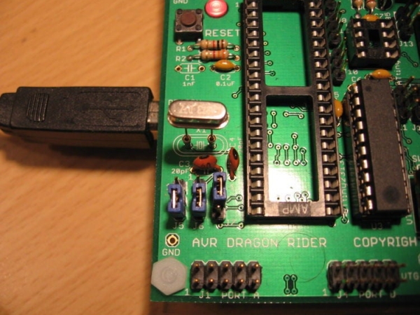
This instructable is a crash course in how to use some of the features of the Dragon Rider 500 from Ecros Technologies. Please be aware that there is a very detailed User’s Guide available on the Ecros website.
The Dragon Rider is a interface board for use with an AVR microcontroller programmer called the AVR Dragon by Atmel.
This instructable may grow with time so check back now and again!
Step 1: AVR Dude
You need some programming software in order to use the AVR Dragon for programming. I use AVRdude with the Ubuntu operating system (linux) and I’m very happy with the results.
My guess is that if you have purchased and assembled a Dragon Rider 500 you already know how to program a chip with the AVR Dragon….. onward!
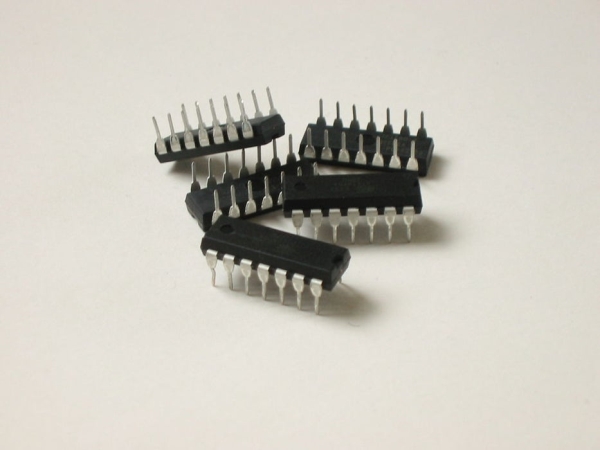
Step 2: ATtiny2313 – Blink the LEDs
Let’s program an ATtiny2313 which is a 20-pin microcontroller.
The Dragon Rider 500 has sockets for several different sized AVR microcontrollers. These include: 8, 20, 28, and 40 pin sockets. Depending on which socket you use, jumpers on the Dragon Rider board must be set differently.
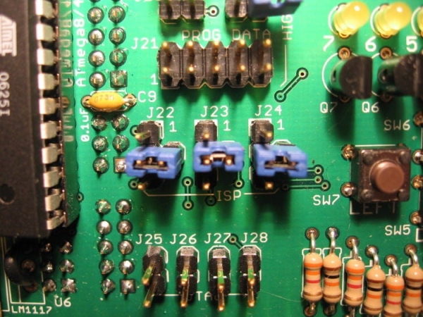
Jumper Settings
Set the jumpers on the Dragon Rider so that the shunts connect the following pins. (pin4 is the center pin for J22-J-24)
This is a basic setup that allows for ISP (In System Programming).
Blinky Blinky
Programming does no good unless you have something to program. I have written a very short code example to blink the Dragon Rider’s LED’s one at a time.
Use a ribbon cable to connect the LED header (J29) to the PortB header (J2).
Programming
I’ve included the C file as well as a makefile and the hex file. Like I mentioned in the intro, I cannot cover the software side of programming in the Instructable. Program like you would for the AVR Dragon, as the Dragon Rider doesn’t alter the software side of things at all.
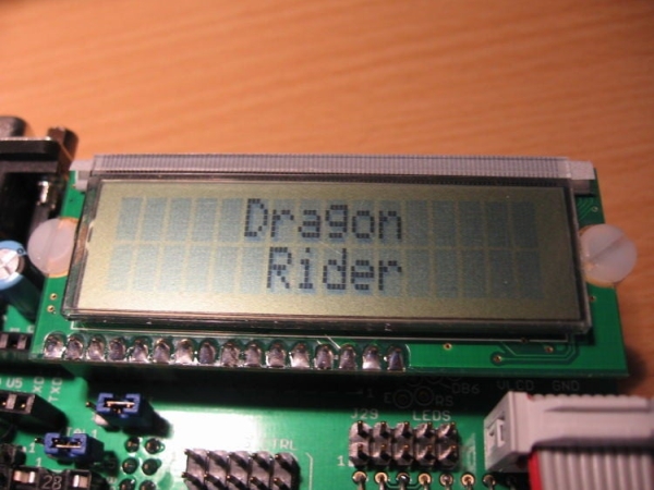
Step 3: Using the LCD Add-on
Here’s a simple way to use the LCD Add-on. This will write “Dragon Rider” to the LCD screen.
Hardware:
ATtiny2313
R/W Jumper: R/W should be connected to “BIT1” on the Dragon Rider Board (See explaination in the Assembly Instructable)
J23: This jumper must be installed for ISP programming but then removed for the LCD to function properly.
Connect LCD to PORT B using ribbon cable (J31 to J2)
Software
I am using Peter Fleury’s LCD library to drive the LCD in 4-bit mode. Check out Peter’s Homepage to download the library.
You will need to make sure that lcd.c is compiled with your code and that you make the following changes to lcd.h:
We are using the internal RC oscillator so XTAL needs to be set for 1MHz:
Port settings need to be adjusted to PORTB:
Pinout for 4 data lines needs to be adapted:
Pinout for RS, RW, and E needs to be adapted:
The main program is very simple thanks to the work Peter Fleury did in his LCD library.
CODE:
#include <avr/io.h>#include "lcd.h"int main(void){ lcd_init(LCD_DISP_ON); //Initialize LCD with the cursor off lcd_clrscr(); //Clear the LCD screen lcd_gotoxy(5,0); //Move cursor to this location lcd_puts("Dragon"); //Put this string on the LCD lcd_gotoxy(6,1); //Move cursor to this location lcd_puts("Rider"); //Put this string on the LCD for (;;) { // Do nothing forever (Message already displayed on LCD) }}
Code Attached
The code attached includes Peter Fleury’s LCD library (lcd.c and lcd.h) with his permission. Thank you Peter! The only alteration I have made to it is to set the proper pins in the Defines. Please visit his site to download the package: http://www.jump.to/fleury
I have also included a makefile that I use written by Eric B. Weddington and, Jorg Wunsch. I sent a PM to Jorg over at avrfreaks.net but never received a response from him. There are a few changes in the makefile to tailor to using Linux and the Dragon. Thank you to you both, please set me know your preferences on me sharing your work.
Step 4: 28-pin UC ISP Programming (ATmega8)
The next project demontration will utilize an ATmega8 which is a 28-pin avr. Here is the the basic jumper set for ISP programming the 28-pin microcontrollers.
Jumper Settings
Set the jumpers on the Dragon Rider so that the shunts connect the following pins. (pin4 is the center pin for J22-J-24)
Connecting J11 and J12 in this fashion allows you to use those pins as I/O pins. The alternative would be to route these pins to make a connection with the external crystal.
Connecting J13 in this fashion allows us to use it as the reset pin. The alternative would route this pin to the PORTC header for use as an I/O pin. (this would have many drawbacks, including the inability to program this chip using ISP).
J16 & J22-J24 are connected in this fashion to route the appropriate pins (Reset, MISO, MOSI, and SCK) to the ISP header of the AVR Dragon.
Step 5: Advanced LCD and Button Usage: the Big Clock
This is a fun project that makes use of the LCD screen and buttons. We will be dealing with Real Time Clock functions and custom characters on the LCD.
In the picture at the bottom you can see the time 7:26:07pm displayed in large numbers on the LCD screen. Each number is using a 2×2 grid of the characters display to show the large number. This utilizes a font originally written by Xtinus for the XBMC project.
The buttons are used to set the clock. Left increments the hours, Up increments the minutes, Right toggles between 12 and 24-hour time, and Enter resets the seconds to zero.
The clock doesn’t keep very good time as we are using the very inaccurate internal oscillator, but this program can easily be altered to use a much more accurate external crystal. See this in action in the video below.
An explaination of how this code works is in order, but I don’t have the time right now.
For now, connect the LCD header (J31) to PORTD (J4) and the button header (J30) to PORTB (J2). Make sure you have both SW1 and SW2 in the off position. Connect the AVR Dragon to a usb cable and plug the other end of that cable into your computer. Turn on SW2 and program the ATmega8 with the programming software of your choice (hex file below; fuses burnt to factory settings).
NOTE: In order to utilize the Left and Up buttons you will need to remove the shunts from J22 and J24, do this while the power is off.
Step 6: High Voltage Programming
I have used the High Voltage Parallel Programming to resurrect an ATtiny2313 that I set the wrong fuse settings on. I needed it a second time when working on this instructable because I accidentally wrote the lfuse setting I wanted to the hfuse register….. ooops. High Voltage parallel programming is a handy tool to have at your disposal!
Below are a lists of my jumper settings:
USE AT YOUR OWN RISK, THIS TYPE OF PROGRAMMING CAN DAMAGE YOUR HARDWARE IF YOU DON’T KNOW WHAT YOU’RE DOING!!
High Voltage Parallel Programming:
ATtiny2313 in socket U3: SW1 – OFF SW2 – ON J5, J6, J7 – connect pin1 and pin2 XTAL1 – connect pin1 and pin2 J16 – Connect pin1 and pin2 2×5 IDC Cables: PROG_CTRL to PORT D, PROG_DATA to PORT B All other jumpers unconnected (J8-J13, J18, J19, J20, J22-J28, J24)
For other chips you should be able to figure out the settings you need from Atmel’s user guide for their STK500.
Step 7: Expanding Beyond the Board
I find it quite easy to interface with a breadboard. This allows for a lot more flexibility in prototyping and developing code at the same time.
Below you will see a couple of breadboards connected to the Dragon Rider. I connect up the ribbon cables to the appropriate ports at one end. At the other I use jumper wires to connected the proper ICD conductor with the breadboards.
Step 8: Conclusion
There is much more that could be involved in this Instructable. Just tonight I complete an adapter that allows you to use the 6-pin programming header without removing the dragon from the Dragon Rider. I’ll be putting information on how to construct one yourself… coming soon. If you have other things you think need to be added leave a comment.
The Swiss AVR Knife bundles a number of AVR programming projects together in a single convenient Altoids Gum Tin. Because of the flexibility afforded by microcontroller programming, it also provides a starting point for any number of projects based on LEDs and sound output. The SAK can contain as many programs as the 8K of memory permits and maintains eight states for each program. The blue pushbutton causes the SAK to cycle through programs and states — a quick press causes it to stay in the program but change to the next state (however that is defined) and a long press causes it to advance to the next program. The current program and states for all programs are preserved in EEPROM between uses.
The projects currently implemented in the SAK include the following. These, along with all of the other code and constants (there is a full font table), take up about 4K of the available space. Lots more room!
This project would not exist without the considerable generosity of everyone who contributed in one way or another. In addition to the abovementioned, I would like to thank the developers of the software tools used (see in other steps) and anyone that put up a useful website that furthered my understanding of these topics. I can take direct credit for very little of the code used in this project. If you feel that the code is yours, it may well be. Let me know and I will happily give you credit. In any case, thank you for your contribution
Step 1: Parts
Parts can be obtained from any of a number of electronic suppliers. Because of the space constraint, most of the components are required as indicated. Everything just barely fits; make sure that any substitute parts don’t take up additional space. Do not substitute for the ATtiny84 unless you are absolutely certain that the pins correspond. The links following the parts are to DigiKey and All Electronics.
Electronic components 1 x U1 — ATtiny84 — ATTINY84-20PU-ND 1 x Ux — IC socket 14-pin DIP — A32879-ND 9 x LED — your choice of color 9 x resistors — matched to your LEDs
2 x R1, R2 — 100 ohm 1/4W �1% metal film — 100XBK-ND 2 x C7, C8 — 47uF — P5151-ND
Minty Boost The SAK is powered by a single AA battery boosted by a Maxim MAX756 chip (the essential component of the MintyBoost!). The components below are those needed for this part of the circuit.
Many projects use either the ATtiny2313 20-pin or the ATtiny85 8-pin microcontroller. I found the ATtiny2313 too big (for the enclosure) and the ATtiny85 too small (not enough memory, not enough output pins). The ATtiny84 is just right
The ATtiny84 has 8K of programmable flash memory (enough to hold lots of small programs), 512K of EEPROM (for storing state between uses), up to 12 output pins (for the 9 LEDs, 2 channels of audio output, and a pushbutton switch), and lots of other goodies that aren’t used in this project.
If you plan on adding programs, obtain a copy of the ATtiny84 datasheet. There are many instructional guides for learning to program this family of microcontroller on the Internet. For a helpful summary of microcontrollers, see How to Choose a Microcontroller.
Note The project described here does not actually have the MiniMenorah fully enabled. The MM requires nine output pins, the Brain Machine two, and the button to change state one, for a total of twelve. While the ATtiny84 can be configured to have twelve output pins, it is at the expense of the RESET pin. Disabling the RESET pin and making it I/O makes the ATtiny84 unable to be programmed with the USBtinyISP progammer (who hasn’t done that and requires High Voltage Programming. Everything is in place to enable the MM, but a different programmer is required, and I don’t have one.
Step 3: AVR Programming Tools
Quite a few components, both hardware and software, are necessary to program AVR microcontrollers. Below are the tools I use. Many, many others exists in the same price range — free to cheap. Find a set that works for you and stick with them. Better yet, find a friend who has worked out a system and use his/her tools. Nothing is particular hard if all goes as advertised, but getting all of the tools working together can be a real challenge.
Programming cradle I based mine on the Ghetto Programming Environment. The long pins of the wirewrap chip holder extend down in to a breadboard and makes for a convenient experimental setup.
The only problem I have encountered is that the components from the programming pins cannot be grounded during programming. I have taken two approaches to solve this problem. The first is to have two chip holders, one for programming and one for running (see 8-pin cradle). This is not ideal because it renders a lot of the breadboard unusable and it is quite annoying to move the chip. The second is to install a small switch to disconnect the ground pin from the ground of the breadboard during programming. This works better and leaves more space on the breadboard for components.
Programmer USBtinyISP kit from Adafruit Industries. With a little modification (remove the 10-pin cable and bend the LEDs) the programmer fits in an Altoids Gum Tin. The 6-pin cable can even be coiled up into the tin for storage.
Software WinAVR is a collection of open source software development tools for programming AVR microcontrollers on Windows machines. It works well with the USBtinyISP programmer (see the AVR Tutorial).
I recently switched from using the Programmer’s Notepad application that comes bundled with WinAVR to using Eclipse with the AVR Eclipse Plugin. Eclipse can use avrdude, so you will have to install WinAVR anyway. Eclipse has better project management, helpful tutorials, and is free. It took just a few minutes to install it, work through a tutorial, and program a chip.
Phone a friend There are lots of resources on the Internet. Look for them, ask for help. People can be knowledgeable and helpful. That’s nice They also can be dismissive. That’s not nice
Step 4: Programming the Microcontroller
C code Don’t criticize what I don’t understand. I am not a programmer, C is not my native language, and I am holding on by a Java-thin thread and a lot of web searching when working in C. Even though much of the code came from other projects (see credits), I did have to make some additions and modifications. The source code for the Swiss AVR Knife is attached below both as a c source file and a hex file. I would appreciate hearing where the code could be improved.
There are a few changes I anticipate making in the code. Updates are forthcoming. In the meantime, the code does work as advertised.
Fuses Microcontroller fuses are confusing. I have disabled a few microcontrollers both by accidentally setting them to look for an external oscillator and by disabling the RESET pin. They can be recovered, but until then they are just dead bugs. Be careful if you choose to change the fuses.
To calculate the correct fuse values, use an online fuse calculator. Select the target part (ATtiny84) and the appropriate settings — internal RC oscillator running at 8MHz (default value), DO NOT divide the clock by 8 internally, enable serial program downloading, and disable brownout detection. The result should be the following.
You only need to burn the fuses once (unless you plan to change them). Eclipse makes this easy, as, I am sure, do other IDEs.
Questions that I would like answered
Any ideas on optimizing the code Why do the blinking lights in the sound and light machine cause an oscillation in tone when enabled in the tin but not on the breadboard? Why doesn’t Eclipse like the lightOn and lightOff functions, even though they seem to work?
Step 5: Breadboarding the Project
Because so much of the work of this project is done by the microcontroller, there are very few external parts. After checking that your programmer and tool chain are in order, it would be a good idea to breadboard the circuit and make sure that everything works as advertised.
The pictures below are messed up versions of the actual breadboard I had set up. I used the LEDs in the model tin and pried out the cradle and chip to use in several photographs. The overall wiring basically connects active pins to a few parts and then on to ground.
Note The order of pins and LEDs is not the same on the breadboard and the PCB (although I suppose you could make them the same). In the code, you will see pieces of code that need to either be enabled or commented out depending on whether the target is the breadboard or the PCB.
Step 6: Preparing the Altoids Gum Tin
Pictures on the way
Flatten the bottom. The bottom of the tin curves up and in. It needs to be flattened so that the battery and circuit board fit and sit evenly. Being careful not to distort the tin, push the bottom out until it is essentially flat.
The tin needs three sets of holes. I use a metal punch to mark the hole locations and brad point bits (for wood) to drill the holes. The brad point bits have a center point and two cutting edges. They won’t skate and the edges cut slowly through the metal. Brad point bits are available from Lee Valley (among other places).
The first is a set of nine 5mm holes across the top of the tin for the LEDs. Metric brad point bits are available and they make clean and snug holes for the LEDs. Create a paper template with the holes marked and transfer the marks to the top of the tin. In order to prevent pushing the top of the tin in, support the inner part of the lid on a small block of wood when punching and drilling the top. With the paper and wood in place, I dimple the tin using the punch. When drilling, go slowly at first. The cutting edges of the brad points should make an even circle. Drilling with the bit anything but perpendicular to the surface may result in the bit grabbing and tearing the metal.
The 5mm brad point makes a nice clean hole, but I found that I had to widen it ever so slightly. I did this by drilling out from the inside with a regular 13/64″ bit.
The second set consists of two 1/4″ holes on the right side of the tin for the switch and audio jack. Because of the tight curvature at the end of the tin, these holes need to be fairly close. Make sure to space them so that the components fit in the tin. Center them vertically on the portion of the side visible when the lid is closed. Mark with punch and drill very carefully. The caution about the bits grabbing the tin applies more strongly with the bigger bits.
The last hole is for the pushbutton switch. Position the hole towards the bottom right in such a way that the pushbutton does not interfere with the other components in the tin.
Hey friends in this instructable I will show you how to interface sony PS2 controller with AVR microcontroller .This will be your handy code which you can be used in future to control robots .You can get analogue value from joystick which can be used to control the speed of motor . I have explained the code with help of 3 section 1)what is SPI ? 2)PS2 protocol 3)Finally the code I have written the code for atmega640 in BIT BANGbut anyone who as worked with AVR can easily write a code for any series atmega microcontroller.You can also check ‘Interfacing PS2 with AVR -SPI ‘ in which i have used internal SPI of AVR.
Let’s get started!
Step 1: Material and Software Required
Materials required 1)sony PS2 controller 2)Atmega640 3)AVRISP programmer(or any other programmer depending upon your microcontroller ) 4)one to one connector
software 1)Winavr(or any AVR compiler) 2)progISP
and of course you should have basic knowledge of AVR programming and embedded C.
Step 2: Understanding SPI
what is SPI ? (you can skip this step if u know SPI communication ) Serial Peripheral Interface Bus or SPI bus is a synchronous serial data link de facto standard, that operates in full duplex mode. Devices communicate in master/slave mode where the master device initiates the data frame. Multiple slave devices are allowed with individual slave select (chip select) lines. Sometimes SPI is called a four-wire serial bus, contrasting with three-, two-, and one-wire serial buses. SPI is often referred to as SSI (Synchronous Serial Interface). In SPI there are 6 connection MOSI-master out slave in MISO-master in slave out SCK-clock is provided by master to slave by this pin SS-slave select ,master selects a slave by this pin VCC-voltage pin GND -ground Both master and slave have shift register when master provides 8 clocks the content of each register is interchanged and data is transferred from master to slave and vice versa thus a full duplex communication .
so what is BIT BANG ? Bit banging is a technique for serial communications using software instead of dedicated hardware. Software directly sets and samples the state of pins on the microcontroller, and is responsible for all parameters of the signal: timing, levels, synchronization, etc. In contrast to bit banging, dedicated hardware (such as a modem, UART, or SPI) handles these parameters and provides a (buffered) data interface in other systems, so software is not required to perform signal demodulation. Bit banging can be implemented at very low cost, and is used in, for example, embedded systems. In this instructable I am using bit bang technique instead of using AVR’s SPI hardware .This code will work fine for many of our task .
Setting a hardware is very easy you have to connect only 6 pins given below.you can use one to one connectors to connect PS2 side with board.Remove the plastic cover of one to one wire and make the gap bigger to fit in PS2 connector and then insulate the cnnector
————-LOOKING AT THE PLUG——————- ——————————- PIN 1-> | o o o | o o o | o o o | \___________________/
you can connect wire as shown in picture above.I have made adapter to connect PS2 controller with the board
Step 5: Explaning the Code
finally the code if u have understood the flowchart this will be quite easy
The code has only 2 function 1) int gameByte(short int command) 2) void int_PS2inanalougemode()
int gameByte(short int command) { short int i ; // variable used as counter _delay_us(1); short int data = 0x00; // clear data variable to save setting low bits later.
for(i=0;i<8;i++) // as 8 bytes are transferred i<8 { if(command & _BV(i)) //each bit of command is ANDED with 1 one by one, thus value of that cmnd is if in condition { sbi(PORTB, PScommand); // if command is one command pin is set } else { cbi(PORTB, PScommand); // else command pin is made zero }
cbi(PORTB, PSclock); // CLOCK LOW _delay_us(1); // wait for output to stabilise
if((PINB & _BV(PSdata))) { sbi(data, i); // read PSdata pin and store } else { cbi(data, i); }
sbi(PORTB, PSclock); // CLOCK HIGH }
sbi(PORTB, PScommand); _delay_us(20); // wait for ACK to pass. return(data);
}
void int_PS2inanalougemode()- this function puts the controller in analogue mode until it returns value 0x73 in 2nd byte which indicates that PS2 controller is in analogue mode if it doesn’t return its increments the counter and continues to put PS2 controller is in analogue mode
int main(void) in main loop we simply poll the input of PS2 controller . video
I recently started programming AVR chips, namely the ATTiny85. They can be programmed using C, compilers are readily available in Ubuntu, and you can do a LOT with them – just search for avr on this site! Anyway, I was having some trouble with my project today – the LED wouldn’t flash! I couldn’t figure out what was going on, as debugging these things is non-trivial. That is, until I discovered simavr.
It’s a simulator for AVR in Linux that can take your ELF or HEX code and run it as if it’s actually on-chip, but gives you hooks and the possibility of dumping trace files. I’ll go through a simple example.
Step 1: Git It
There are a few dependencies on Ubuntu (which is what I use all the time):
I had to remove some crappy Mesa symlink for OpenGL in 10.10. Only do this if you have problems compiling related to -lGL,
sudo rm /usr/lib/libGL.so
cd /usr/lib
sudo ln -s libGL.so.1 libGL.so
cd
Finally, use git to download the source code:
git clone git://gitorious.org/simavr/simavr.git
Now, build it.
cd simavr
make
If you get any errors, leave me a comment. I’d be happy to help. You should have a new program called run_avr in the simavr subdirectory once that completes.
Step 2: Try a Test
There’s tons of tests that come with the software. They’re located in the (surprise!) tests subdirectory in the code. You can run one like this:
./run_avr ../tests/atmega88_example.axf
You should see something like this:
AVR_MMCU_TAG_VCD_TRACE 00c6:00 - UDR0
AVR_MMCU_TAG_VCD_TRACE 00c0:20 - UDRE0
Loaded 1760 .text
Loaded 114 .data
Loaded 4 .eeprom
Starting atmega88 - flashend 1fff ramend 04ff e2end 01ff
atmega88 init
avr_eeprom_ioctl: AVR_IOCTL_EEPROM_SET Loaded 4 at offset 0
Creating VCD trace file 'gtkwave_trace.vcd'
Read from eeprom 0xdeadbeef -- should be 0xdeadbeef..
Read from eeprom 0xcafef00d -- should be 0xcafef00d..
simavr: sleeping with interrupts off, quitting gracefully
Notice it made a VCD trace file? Let’s see what that looks like in GTKWave!
Step 3:
gtkwave gtkwave_trace.vcd
You can drag and drop the Signals on the left into the Signals list by the Waves dialog to make them show up. You can also right click the Signals and change their properties (like making them display in binary).
Step 4: How It Worked for Me
You specify the chip you want to simulate on the command line, and you can give it the object file created by avr-gcc (ELF format) to make it run. I also specified the frequency here as 8Mhz.
Now that I had the trace file, I looked at it with gtkwave like in step 3. I used my datasheet and compared the registers with what I expected, and I was setting my timer registers backwards! Whoops! Anyway, it would have taken me a much longer amount of time to solve it without simavr – this way it only took a few minutes to get it up and running and find my problem. I highly recommend you try it out!
If you’d like to see some sample code, here’s the source for the test I did above:
Temperature Sensor(LM35 ) is a popular and low cost temperature sensor. The Vcc can be from 4V to 20V as specified by the datasheet. To use the sensor simply connect the Vcc to 5V ,GND to Ground and the Out to one of the ADC (analog to digital converter channel).
The output is 10MilliVolts per degree centigrade. So if the output is 310 mV then temperature is 31 degree C. To make this project you should be familiar with the ADC of AVRs and also using LCD So The resolution of AVRs ADC is 10bit and for reference voltage you are using 5V so the resolution in terms of voltage is
5/1024 = 5.1mV approximately
So if ADC’s result corresponds to 5.1mV i.e. if ADC reading is
10 x 5.1mV = 51mV
You can get read the value of any ADC channel using the function adc_result(ch);
Where ch is channel number (0-5) in case of ATmega8. If you have connected the LM35’s out put to ADC channel 0 then call
adc_result0 = adc_read(0);
this will store the current ADC reading in variable adc_value. The data type of adc_value should be int as ADC value can range from 0-1023.
As we saw ADC results are in factor of 5.1mV and for 1 degree C the output of LM35 is 10mV, So 2 units of ADC = 1 degree.
So to get the temperature we divide the adc_value by two
temperature = adc_result0 /2;
Finally the microcontroller will display the temperature in degree centigrade in the 16X2 alphanumeric LCD.
Step 2: Circuit Diagram
Step 3: Program
#ifndef F_CPU
#define F_CPU 1600000UL
#endif
#include
#include
#include “LCD/lcd.h”
void adc_init()
{
// AREF = AVcc
ADMUX = (1<
// ADC Enable and prescaler of 128
ADCSRA = (1<
}
// read adc value
uint16_t adc_read(uint8_t ch)
{
// select the corresponding channel 0~7
ch &= 0b00000111; // AND operation with 7
ADMUX = (ADMUX & 0xF8)|ch;
// start single conversion
// write ‘1’ to ADSC
ADCSRA |= (1<
// wait for conversion to complete
// ADSC becomes ‘0’ again
while(ADCSRA & (1<
return (ADC);
}
int main()
{
DDRB=0xff;
uint16_t adc_result0;
int temp;
int far;
char buffer[10];
// initialize adc and lcd
adc_init();
lcd_init(LCD_DISP_ON_CURSOR); //CURSOR
lcd_clrscr();
lcd_gotoxy(0,0);
_delay_ms(50);
while(1)
{
adc_result0 = adc_read(0); // read adc value at PA0
temp=adc_result0/2.01; // finding the temperature
//lcd_gotoxy(0,0);
//lcd_puts(“Adc=”);
//itoa(adc_result0,buffer,10); //display ADC value
//lcd_puts(buffer);
lcd_gotoxy(0,0);
itoa(temp,buffer,10);
lcd_puts(“Temp=”); //display temperature
lcd_puts(buffer);
lcd_gotoxy(7,0);
lcd_puts(“C”);
far=(1.8*temp)+32;
lcd_gotoxy(9,0);
itoa(far,buffer,10);
lcd_puts(buffer);
lcd_gotoxy(12,0);
lcd_puts(“F”);
_delay_ms(1000);
if(temp>=30)
{lcd_clrscr();
lcd_home();
lcd_gotoxy(0,1);
lcd_puts(“FAN ON”);
PORTB=(1<
}
if (temp<=30)
{
lcd_clrscr();
lcd_home();
lcd_gotoxy(7,1);
lcd_puts(“FAN OFF”);
PORTB=(0<
}
}
}
Step 4: Code Explain
I hope you Know you will know How to enable ADC and How to interface LCD with Avr Microcontroller in this code when temperature is more then 30 degree then fan is on and you can see on led Display FAN ON and when Temperature Less then 30 then fan is off and you can see FAN OFF
A digital thermometer is a good project in microcontrollers because it provides an opportunity to learn using sensors to measure the real world signals that are analog in nature. I am trying to describes a similar project based on a Atmega32 microcontroller and an LM35 temperature sensor. LM35 is an analog sensor that converts the surrounding temperature to a proportional analog voltage. The output from the sensor is connected to one of the ADC channel inputs of the Atmega32 microcontroller to derive the equivalent temperature value in digital format. The calibrated temperature is displayed in a 16×2 character LCD, in both °C and °F scales.
LM35 The LM35 series of temperature sensors are produced by National Semiconductor Corporation and are rated to operate over a -55 °C to 150°C temperature range. The scale factor for temperature to voltage conversion is 10 mV per °C. The LM35 series sensors come in different packages.
The output voltage from the sensor is converted to a 10-bit digital number using the internal ADC of the aTMEGA32 Since the voltage to be measured by the ADC ranges from 0 to 1.0V (that corresponds to maximum temperature range, 100 °C), the ADC requires a lower reference voltage (instead of the supply voltage Vdd = 5V) for A/D conversion in order to get better accuracy.
Step 1: LM35 WITH ADC/DAC Temperature Calculation
In ATMEGA32A, we can give Analog input to any of eight channels of PORTA. We are going to choose channel 0 or PIN0 of PORTA. In ATMEGA32A, the ADC is of 10 bit resolution, so the controller can detect a sense a minimum change of Vref/2^10, so if the reference voltage is 5V we get a digital output increment for every 5/2^10 = 5mV. So for every 5mV increment in the input we will have a increment of one at digital output.
..
Setting the register of ADC: 1.First of all we need to enable the ADC feature in ADC.
2. Since we are measuring room temperature, we don’t really need values beyond hundred degrees (1000mV output of LM35). So we can set up maximum value or reference of ADC to 2.5V.
3. The controller has a trigger conversion feature, that means ADC conversion takes place only after an external trigger, since we don’t want that we need to set the registers for the ADC to run in continuous free running mode.
4. For any ADC, frequency of conversion (Analog value to Digital value) and accuracy of digital output are inversely proportional. So for better accuracy of digital output we have to choose lesser frequency. For lesser ADC clock we are setting the presale of ADC to maximum value (128). Since we are using the internal clock of 1MHZ, the clock of ADC will be (1000000/128).
For Ex,:
Lets assume that your other temperature measurement source is accurate at 23C.
To calibrate, adjust your Vref pot until your A/D reading is 94 ((10mV x 23)/2.5) x 1024 = 94. Oh, forget about the “+2” in your transfer function. The correct transfer function is 10mV per degree C. The “+2” is the minimum temperature that is measurable with the common pin of the sensor grounded.
Now for the scaling to convert A/D reading back to degrees C. We know that our A/D reading (with 2.5V ref) should be 94 (also assuming no errors in the A/D). So, we have 94=23. Find the scale (23/94 ~= 0.2446805). Now, we will multiply our scale by a nice binary power of 2 (256). So, our new scale is 0.2446805 x 256 ~= 63.
Now, we take our A/D reading (94) multiplied by our new scale (63). Then, after the multiplication we divide out the (256).
Final result = (94 x 63)/256 ~= 23.
There are techniques for rounding the result as well. If the accuracy of the math is not acceptable, then a larger multiplier can be used (say 65536 instead of 256).
Step 2: ADC Temperature Conversion
RED (ADEN): This bit has to be set for enabling the ADC feature of ATMEGA. BLUE(REFS1,REFS0): These two bits are used to set the reference voltage (or max input voltage we are going to give). Since we want to have reference voltage 2.56V, REFS0 and REFS1 both should be set, by the table-1.
LIGHT GREEN (ADATE): This bit must be set for the ADC to run continuously (free running mode). PINK (MUX0-MUX4): These five bits are for telling the input channel. Since we are going to use ADC0 or PIN0, we need not set any bits as by the table-2.
BROWN (ADPS0-ADPS2): these three bits are for setting the prescalar for ADC. Sice we are using a prescalar of 128, we have to set all three bits.(Table-3).
DARK GREEN (ADSC): this bit set for the ADC to start conversion. This bit can be disabled in the program when we need to stop the conversion.
Step 3: Circuit Diagram for LM35, ATmega32,HD44780U (LCD-II)
ATmega32 belongs to Atmel’s AVR series 8-bit micro controller family.
Atmega32 has is of 40 pins chip. Two for Power (pin no.10: +5v, pin no. 11: ground), two for oscillator (pin 12, 13), one for reset (pin 9), three for providing necessary power and reference voltage to its internal ADC, and 32 (4×8) I/O pins.
About I/O pins: ATmega32 is has analogue inputs. Port A can be used as either DIGITAL I/O Lines or each individual pin can be used as a single input channel to the internal ADC of ATmega32, plus a pair of pins AREF, AVCC & GND(Datasheet: Atmega32).
There is no complexity for connection. Just connect according to given Diagram……
Resistance used near lcd-V0 (1k Ohms).
Step 4: Code (Atmega32, LCD, LM35)
First of all, coding in any editor like notepad or any text-editor and compiling and loading in a toolchain:
1) Cygwin (Linux console over windows)
2) GNU Binutils
3) GCC (opensource compiler=cross compiler)
4) WinAVR (AVR Library for windows)
5) Avrdude(Burning Software into Chip)…
All these in combination works fine. We can work on any type of Atmel-Avr Chipsets using these tool chain.
You can get it from: http://winavr.sourceforge.net/
WinAVR is a suite of executable, open source software development tools for the Atmel AVR series of RISC microprocessors hosted on the Windows platform. It includes the GNU GCC compiler for C and C++.
/*LCD MODULE INFORMATION! The maximum time required by each instruction for the slowest lcd units is 4.1 msecs for clearing the display or moving the cursor/display to the “home position”, 160 usecs for all other commands. (i use 50 because i use good units)
Usual HD44780 Pins connections
1 = Ground
2 = Vcc
3 = Contrast Voltage
4 = “R/S” _Instruction/Register Select
5 = “R/W” _Read/Write LCD Registers (See the connection table for additional information).
6 = “E” Clock
7 – 14 = Data I/O Pins 0 to 7 (0=7, 1=8,… 7=14 )
15 – Vcc for the BACKLIGHTING (Check to be sure because some units have it for Gnd)
16 – Gnd for the BACKLIGHTING (Check to be sure because some units have it for Vcc)
TYPICAL CONNECTION TABLE AS USED IN THIS lcd_io.h FILE. ACTUALLY YOU CAN USE ANY PIN AS LONG AS THE PIN CARRIES THE CORRECT SIGNAL TO THE CORRECT LCD PIN.
port_pin0 -> lcd_D4_pin11 port_pin1 -> lcd_D5_pin12 port_pin2 -> lcd_D6_pin13 port_pin3 -> lcd_D7_pin14 port_pin4 -> lcd_RS_pin4 port_pin5 -> lcd_E_pin6 GND -> lcd_RW_pin5 if lcd reading is not needed or when using mode 2 or mode 7 port_pin6 -> lcd_RW_pin5 if lcd reading is needed in mode 6 only
/*######################################################################################################*/ /* CONFIGURATION BLOCK STARTS HERE. Change these definitions to adapt setting */ /*######################################################################################################*
***********************************************************************************************/ /* GLOBAL SETTINGS (settings described here are applyied everywhere) */ /***********************************************************************************************/ /* */
#ifndef F_CPU #define F_CPU 8000000 /* CPU CLOCK FREQUENCY */ #endif
/* 1 = Auto line feed, 0 = no Auto line feed */ #define LCD_AUTO_LINE_FEED 0
/* THE TYPICAL TIME THE LCD NEEDS TO COMPLETE A COMMAND */ #define LCD_DELAY_TIME_US 100
/* THE E PULSE WIDTH IN MICROSECONDS (Timing is accurate)*/ #define LCD_E_PULSE_WIDTH_US 1
/* The decimal point punctuation mark char */ #define LCD_DECIMAL_POINT ‘.’
/* WAYS TO REDUCE CODE SIZE BY NOT COMPILING UNWANTED FUNCTIONS OR CODE * PORTIONS */ /* 1=function available, 0=not available. */ #define LCD_PUT_I_NEEDED 1 #define LCD_PUTS_NEEDED 1 #define LCD_PUTS_P_NEEDED 1 #define LCD_PUTS_E_NEEDED 1 #define LCD_PUTC_CGRAM_NEEDED 1 #define LCD_CLRLINE_NEEDED 1 #define LCD_GETXY_NEEDED 0 /* 1=limit, error & control chars checking disabled. Also auto line feed off. * For experts only! */ #define LCD_SAVE_MORE_CODE_SPACE 0
/*********************************************************************/ /* START OF SELECTED MODE CONFIGURATION BLOCK */ /*********************************************************************
***************************************************************************/ /* START OF MODE 6 CONFIGURATION BLOCK */ #if LCD_IO_MODE == 6 /***************************************************************************/ /* CONFIGURATION OF BELOW LINES ONLY NECESSARY IF YOU SELECTED MODE 6 IN GLOBAL SETTINGS If you plan to use just one port for all pins then just edit “LCD_PORT” otherwise you must specify the port of each lcd signal. the port(s) must be able to function as output. It can be any combination! PUT YOUR LCD PORT LETTER HERE USING CAPITAL LETTER (A,B,C,D…etc) */ #define LCD_CHARS_PER_LINE 16 /* visible chars per lcd line */ #define LCD_LINES 2 /* visible lines *
* 1=the DDR’s used are saved and restored */ #define LCD_MULTIPLEX_ENABLE 0 /* 0=use delay, 1=read busy flag & data (7 pins needed) */ #define LCD_READ_REQUIRED 0
/* This enables the backup functions that backup and restore the lcd display. LCD_LINES X LCD_CHARS_PER_LINE bytes are needed (That means 80 bytes for a 4 x 20 lcd display). 0=lcd screen backup location is eeprom, 1=lcd screen backup location is ram. If you need to backup less, use the lcd_getc function. When using the lcd_getc() function the Address Counter (AC) is auto incremented or decremented according to the ENTRY MODE selected during initialization, just like the lcd_putc() function works, so when doing a sequential read, there is no need to reposition the cursor each time a read is performed. The backup & restore settings are valid only if LCD_READ_REQUIRED == 1 */ #define LCD_BACKUP_REQUIRED 0 #define LCD_BACKUP_LOCATION 0
#define LCD_PORT C
#define LCD_DATA4_PORT D /* port for data 0 pin */ #define LCD_D4_PIN 7 /* AVR port pin number */
#define LCD_DATA5_PORT D /* port for data 1 pin */ #define LCD_D5_PIN 6 /* AVR port pin number */
#define LCD_DATA6_PORT D /* port for data 2 pin */ #define LCD_D6_PIN 5 /* AVR port pin number */
#define LCD_DATA7_PORT B /* port for data 3 pin */ #define LCD_D7_PIN 3 /* AVR port pin number */
#define LCD_RS_SIGNAL_PORT B /* port for RS line */ #define LCD_RS_PIN 1 /* AVR port pin number */
#define LCD_E_SIGNAL_PORT B /* port for Enable line */ #define LCD_E_PIN 2 /* AVR port pin number *
* YOU NEED TO EDIT “LCD_RW_SIGNAL_PORT” AND “LCD_RW_PIN” ONLY IF * “LCD_READ_REQUIRED == 1” */ #if LCD_READ_REQUIRED == 0 #define LCD_RW_SIGNAL_PORT LCD_PORT /* port for R/W line */ #define LCD_RW_PIN 6 /* AVR port pin number */ #endif
#endif /* #if LCD_IO_MODE == 6 */ /**************************************************************************/ /* END OF 6 PIN CONFIGURATION BLOCK */ /**************************************************************************
#define LCD_LINE_LENGTH 0x40 /* internal line length */ #define LCD_START_LINE1 0x00 /* DDRAM address of first char of line 1 */ #define LCD_START_LINE2 0x40 /* DDRAM address of first char of line 2 */ #define LCD_START_LINE3 0x14 /* DDRAM address of first char of line 3 */ #define LCD_START_LINE4 0x54 /* DDRAM address of first char of line 4 *
*************************************************************/ /* INSTRUCTION REGISTER BIT POSITIONS AND COMBINATIONS */ /*************************************************************/ #define LCD_CLR 0 /* DB0: clear display */ #define LCD_HOME 1 /* DB1: return to home position */ #define LCD_ENTRY_MODE 2 /* DB2: set entry mode */ #define LCD_ENTRY_INC 1 /* DB1: 1=increment, 0=decrement */ #define LCD_ENTRY_SHIFT 0 /* DB2: 1=display shift on */ #define LCD_ON 3 /* DB3: turn lcd/cursor on */ #define LCD_ON_DISPLAY 2 /* DB2: turn display on */ #define LCD_ON_CURSOR 1 /* DB1: turn cursor on */ #define LCD_ON_BLINK 0 /* DB0: blinking cursor ? */ #define LCD_MOVE 4 /* DB4: move cursor/display */ #define LCD_MOVE_DISP 3 /* DB3: move display (0-> cursor) ? */ #define LCD_MOVE_RIGHT 2 /* DB2: move right (0-> left) ? */ #define LCD_FUNCTION 5 /* DB5: function set */ #define LCD_FUNCTION_8BIT 4 /* DB4: set 8BIT mode (0->4BIT mode) */ #define LCD_FUNCTION_2LINES 3 /* DB3: two lines (0->one line) */ #define LCD_FUNCTION_10DOTS 2 /* DB2: 5×10 font (0->5×7 font) */
#define LCD_CGRAM 6 /* DB6: set CG RAM address */ #define LCD_DDRAM 7 /* DB7: set DD RAM address */
#define LCD_BUSY 7 /* DB7: LCD is busy *
* function set: set interface data length and number of display lines */ #define LCD_FUNCTION_4BIT_1LINE 0x20 /* 4-bit interface, single line, 5×7 dots */ #define LCD_FUNCTION_4BIT_2LINES 0x28 /* 4-bit interface, dual line, 5×7 dots */ #define LCD_FUNCTION_8BIT_1LINE 0x30 /* 8-bit interface, single line, 5×7 dots */ #define LCD_FUNCTION_8BIT_2LINES 0x38 /* 8-bit interface, dual line, 5×7 dots *
* Lcd default mode used in this driver */ #define LCD_MODE_DEFAULT ((1<
/********************************************************************************************************/ /* LCD COMMANDS (CAN BE USED WITH “lcd_command(cmd);”) */ /********************************************************************************************************/ /* set entry mode: display shift on/off, dec/inc cursor move direction */ #define LCD_ENTRY_DEC 0x04 /* display shift off, dec cursor move dir */ #define LCD_ENTRY_DEC_SHIFT 0x05 /* display shift on, dec cursor move dir */ #define LCD_ENTRY_INC_ 0x06 /* display shift off, inc cursor move dir */ #define LCD_ENTRY_INC_SHIFT 0x07 /* display shift on, inc cursor move dir *
* display on/off, cursor on/off, blinking char at cursor position */ #define LCD_DISP_OFF 0x08 /* display off */ #define LCD_DISP_ON 0x0C /* display on, cursor off */ #define LCD_DISP_ON_BLINK 0x0D /* display on, cursor off, blink char */ #define LCD_DISP_ON_CURSOR 0x0E /* display on, cursor on */ #define LCD_DISP_ON_CURSOR_BLINK 0x0F /* display on, cursor on, blink char */ #define LCD_CLEAR_SCREEN (1<
/* move cursor/shift display */ #define LCD_MOVE_CURSOR_LEFT 0x10 /* move cursor left (decrement) */ #define LCD_MOVE_CURSOR_RIGHT 0x14 /* move cursor right (increment) */ #define LCD_MOVE_DISP_LEFT 0x18 /* shift display left */ #define LCD_MOVE_DISP_RIGHT 0x1C /* shift display right *
********************************************************************************************************/ /* PUBLIC FUNCTION PROTOTYPES */ /********************************************************************************************************
* MANUAL LCD INITIALIZATION IS NOT NEEDED ANYMORE. IT IS DONE AUTOMATICALLY! An exception is when “LCD_SAVE_MORE_CODE_SPACE == 1”. Then a call to “lcd_init()” is needed. */ /* HIGH level functions */ extern void lcd_init(void); #if NUMBER_OF_LCD_UNITS >= 2 extern void select_lcd(unsigned char lcd_unit); #endif extern void lcd_command(unsigned char cmd); extern void lcd_gotoxy(unsigned char lcd_x, unsigned char lcd_y); extern void lcd_putc(unsigned char c); extern void lcd_puts(const unsigned char *s); #if LCD_PUT_I_NEEDED == 1 extern void lcd_put_i(int value, unsigned char dot_position, unsigned char number_of_chars) ; #endif #if LCD_PUTS_P_NEEDED == 1 extern void lcd_puts_p(const unsigned char *progmem_s); #endif #if LCD_PUTS_E_NEEDED == 1 extern void lcd_puts_e(unsigned char *eeprom_s); #endif #if LCD_PUTC_CGRAM_NEEDED == 1 extern void lcd_putc_cgram(const unsigned char *user_char, unsigned char char_position); #endif #if LCD_CLRLINE_NEEDED == 1 extern void lcd_clrline(unsigned char line); #endif #if LCD_GETXY_NEEDED == 1 /* The return value of the “lcd_getxy()” function is an integer, with the high byte containing the current line number (y) and the low byte containing the char position in that line (x). If the lower byte has a value of 20 that means that you filled that line. This position result can only happen when no lcd reading is available. When lcd reading is available the maximum x == 19. */ extern unsigned int lcd_getxy(void); #endif #if LCD_READ_REQUIRED == 1 extern unsigned char lcd_getc(void); #if LCD_BACKUP_REQUIRED == 1 extern void lcd_backup_scr(void); extern void lcd_restore_scr(void); #endif #endif
/* The lcd_puti is actually a macro of the lcd_put_i(x,y,z) function with z set to 0xFF. x= the signed 16 bit number, y= the decimal digits wanted and z the number of reserved lcd chars. x must be between -32767 and +32767 and y from 0 to 5 max. z bigger than 8 is ignored and the number gets as many lcd chars as it needs (325 will get 3 lcd chars and -1 will get 2 lcd chars). Maximum char count case is lcd_put_i(-32767,5,8);. The display should show -0,32767 (8 chars) The chars are now left alligned so if you reserve lets say 5 digits for a 3 digit number like 325 then the display will show 325+space+space (Of course you can’t see the spaces).
More examples:
a) We give the command lcd_puti(var_name,0); and var=325 The display will show 325 b) We give the command lcd_puti(var_name,2); and var=325 The display will show 3,25 c) We give the command lcd_put_i(var_name,3,5); and var=325 The display will show 0,325 d) We give the command lcd_put_i(var_name,4,4); and var=325 the whole number is 0,0325 but since you reserved only 4 digits the display will show 0,03 e) We give the command lcd_put_i(var_name,1,6); and var=(-325) The display will show -32,5+space f) We give the command lcd_put_i(var_name,1,3); and var=(-325) the whole number is -32,5 but since you reserved only 3 digits the display will show -32 *
**************************************************************************/ /* FUNCTION RESEMBLING MACROS */ /**************************************************************************/
#endif //LCD_IO_H /*######################################################################################################*/ /* T H E E N D */ /*######################################################################################################*/
I want to share my experiment with voltage divider, ADC and AVR Homemade battery monitor using AVR It’s pretty simple the sensor are only two resistors and zener diode with capasitor, I don’t buy them, I’ve found it in my box. We can use it for monitoring our car battery voltage.
Step 1: The Part I Used
1.ATMEGA128 2.10K and 56K resistors as a voltage divider 3. 5V1 Zener diode 4. 1uF Caps, 5. 16×2 LCD 6. 3 wires to connect the sensor into ADC
Let’s continue to the code
Step 2: The Code and Atmel Studio
Guys, the main key for this experiment is ADC and calculation, you can calibrate first with 5V from 7805
This is the equation I used adcA = ((int)((5000/1024)*adc_result));
This Instructable was designed to answer the question: how do I get started in microcontrollers? Now, in clear, simple English, you can learn what a microcontroller is, and how to use one. You will learn how to make everything that you need to get started. This does require a Windows PC with at least one USB port.
In eighteen easy steps, you will learn what a microcontroller is, how to put one together, how to program it and how to interface the microcontroller to simple input and output devices. All of the components, including the microcontroller itself, are are easily obtained from many different sources, or you may purchase a complete kit from GranzTronix (https://www.tindie.com/products/Granzeier/introduction-to-microcontrollers/.) You will get all of the parts that you need in the kit, but you do not need the kit – all of the experiments may be completed with the information provided in this ‘ible.
Your introduction text ebook, including the assembly instructions for the purchased kit (skip this part if you build your own following this Instructable,) all quizzes and answers and the sample programs, may be downloaded from our web site at: http://files.granzeier.com/Downloads/2313ES.pdf. The steps in this ‘ible are like a Reader’s Digest version of the ebook.
Required Parts:
You will need a few parts for this project. You can get most of these from your local Radio Shack, or you may mail order them from any of many different supply houses.
a breadboard – you will need at least an 800-terminal breadboard, but that will give you limited expansion space. The breadboard I show in these pictures provides two 800-terminal breadboards with dual power rails for each one.
an AVR programmer – we use the USBASP programmer here. I routinely find these on eBay for well under $5.00 delivered. If you choose a different model, you will need to modify the directions in this ‘ible accordingly.
a way to connect the programmer to your breadboard. In step 4, I mention two ways to accomplish this.
3 low-voltage, low-current LEDs (plus one more if you would like a pilot light to indicate when your dev kit is powered.
An Atmel AVR ATtiny2313 microcontroller (this is also included in the GranzTronix kit.)
optional – a 5V power source. Your dev kit can be totally powered by the programmer, this is only needed if you would like to disconnect your computer and take your experiments out to show them off. The kit comes with a battery box, using 4 AA-cells for a total of 4.8V or 6V, depending upon the type of cells used.
As mentioned earlier, you may build this system, and go through all of the experiments shown here (and the others in the book,) or you may purchase a complete set of all parts, including a professionally developed PCB (printed circuit board,) from GranzTronix (https://www.tindie.com/products/Granzeier/introduction-to-microcontrollers/.)
Step 1: What Is a Microcontroller?
Before you can design with a microcontroller, you really need to know what one is. Microcontrollers are all around you, although you may not even realize it. Many people seem overawed by the thought of a microcontroller. A while ago, I spoke to a woman who, when I told her that I work with microcontrollers, replied that those things were far beyond her. I responded that maybe she could not design with them yet, but that she uses those small computers all the time. She appeared to think that I was nuts to suggest that she could even be involved, in any way, with that kind of “high tech” stuff. These microcontrollers are the brains in many products around the home and office. These microcontrollers can be found in watches, microwave ovens, telephones, cars and trucks, DVD players and robots, in fact almost every product that has a display will use at least one of these microcontrollers. So, most people in industrialized nations are already microcontroller users, even though they don’t think of themselves that way.
What is a computer?
A microcontroller is a type of computer, so what is a computer? All computers are made up of four major units. These include the Input unit, the Output unit, the Central Processing unit and the Memory unit. The Input unit is the way that the computer gets the data on which it will do it’s work. Most people know about input devices attached to their desktop computers, devices like their keyboard and their mouse. The Central Processing unit performs the work of running the computer’s programs. This is made up of a Control Unit and an Arithmetic/Logic Unit (also called an ALU). Together these two units make up the Central Processor Unit, or CPU. While working, the CPU keeps it’s instructions, or the program, along with the data on which it is working, in the Memory unit. After the computer does it’s computing, it will present the results of that work thru the output unit. Some of the output devices attached to your desktop computer would be the video display and the printer. A microprocessor combines the two parts of a computer’s CPU (the Control Unit and the ALU) into one single integrated circuit (IC) or chip.
A computer can do a vast number of different jobs. The computers with which you may be most familiar are the ones that sit on or next to your desk and run Windows or Linux or maybe MacOS. These general-purpose computers will help you type a letter or term paper, balance your checkbook or your accounting books, or maybe research different topics by letting you browse the Web. A whole other type of job is for the computer to run (or control) a piece of equipment. By connecting the electrical lines in a computer’s input unit to different switches or sensors, and connecting the electrical lines in that computer’s output unit to lights, motors and other such devices, a computer can control things like an assembly line, a microwave oven, a stereo, or even something like a plane or space ship. In fact, anything that can be operated by one or more switches can be connected to an output line and controlled by a computer. These computers, which are dedicated to the control of equipment, are called Control Computers, or simply Controllers.
In the same way that a Microprocessor combines the two parts of a Control Unit into one IC, a Microcontroller combines the four parts of a computer onto one single IC – these ICs are specially crafted to include things useful for controlling equipment. Thus, they are called microcontrollers.
As you can see, there is nothing inherently complex about microcontrollers; they are simply small control computers integrated onto a single chip. The microcontroller on your Tiny2313 Experimenter System is an IC (or chip) from Atmel, called the AVR ATtiny2313A.
Step 2: Tell Me What You Want Me to Do.
A computer is only as useful as a doorstop between uses, without a program to tell it what to do. The process of giving the computer instructions to perform a task is called programming. A program is pretty much just a list of instructions to the computer. Since a computer only knows about the presence or absence of voltage levels, the Tiny2313 chip uses voltage levels to tell it what to do. All of the instructions and data inside the Tiny2313 are actually voltage levels of either (about) 5 volts or 0 volts. We represent these voltage levels as ones and zeros for our convenience, not for the computer’s convenience. However, as good as those representations are, they are still not very easy for humans. Shortly after computers started coming on the scene, humans wrote tools to help with programming these machines. Some of the first tools were language translators, which took a more human-like language, and translated that into ones and zeros for the computer. Higher level languages, or languages which are closer to human languages, make it easier for a programmer to tell the computer what to do. The process of translating these “high” level languages into the computer’s machine language is called compiling.
MCS Electronics produces a language compiler called BASCOM-AVR for Atmel’s AVR family. BASCOM is a variant of the BASIC programming language. This language was invented by two professors, at Dartmouth College in the 1960s, specifically for beginners. In fact, the name BASIC is an acronym, which stands for Beginners All-purpose Symbolic Instruction Code; in other words, it is a general (All-purpose) Code, for Beginners to give the computer Symbolic Instructions to perform a job. It was designed to be easy to learn and to allow non-computer students to quickly be able to write programs for the university’s computer system. The free trial version, of this BASIC, is limited only in the size of the program. This limit is 4K bytes, which makes BASCOM-AVR an easy match for learning about microcontrollers with the Tiny-2313. You can download this language from MCS’s web site.
Getting the Latest Version In this book, we will be installing and using BASCOM-AVR. You will need to get the newest version from MCS Electronics, the publisher:
1. Go on the web to http://www.mcselec.com and click on Downloads on the left side of the screen.
2. On the Downloads page, click on the BASCOM link at the bottom of the Downloads list on the right side of the page.
3. On the BASCOM page, click on the BASCOM-AVR link at the top of the list of downloads.
4. On this page, click on the link to download the BASCOM-AVR Demo version.
5. On the Terms and Conditions page, click the radio button for “I agree” and then click the button to proceed. This will open the download dialog box, make sure that the “Save file” radio button is selected and click the OK button.
6. In the Save to dialog box, select your desktop and click the Save button.
7. Click on the back button on your browser to return to the BASCOM AVR download page and also download the manual. This has lots of information and is very well organized. 8. Also, on the BASCOM-AVR page, you will find more information about BASCOM-AVR, including articles written about this compiler.
9. Close, or minimize, your browser.
10. Follow the directions to install BASCOM-AVR (you may follow the directions from MCS Electronics, or those in the ebook.)
Step 3: You’re Driving Me Nuts.
While you will be writing your programs for the Tiny2313 on your PC, you will need to transfer that program to the Tiny2313 chip, itself, in order to let the controller run the program. To put the program into your microcontroller, you must have some way to get the program from your PC into the chip. The way engineers used to do this was by taking the chip and placing it into a special device called a programmer. There is a picture of my old Fun Card AVR programmer for ATtiny2313 controllers above. After running the programming software, you would take the chip with the program in it and place it into your circuit. If, or rather when, you discovered an error in your program, you would take the chip out of the circuit, put it into a special device to erase the program (often taking hours), put it back into the programmer, and start the whole process again. This would happen over and over until either you got the program correct, or (often) you just got tired and quit.
We will be using what is called an ISP Downloader Cable. The ISP abbreviation stands for In System Programmer; this is a way that engineers have developed to get around that old way of using a dedicated programmer. We have a special ISP connector on the microcontroller board, and will just connect the programming cable to the board in order to download the program. All of the programming activity is accomplished on the circuit board and the microcontroller chip itself. No need to pull the chip out and move it around.
The ISP that you ordered with your kit is called a USBASP Programmer. We mentioned that programmer earlier, when talking about how to set up BASCOM-AVR.(If you purchased a different model, you will need to modify this Instructable appropriately.)
In order for your computer to be able to use a piece of hardware, you will need to tell it how. The way that you do this is to load a program, called a driver. A driver is just a program that tells your computer how to talk to an attached device. There are drivers, built in to Windows, to tell your computer how to use the mouse, how to read the keyboard, how to display pictures and text on the screen. The USBASP Programmer is not something that everyone uses, though and so, we need to install the driver for that Programmer.
If you do not want to get a kit, you will need to build your own Development Kit (dev kit.) The best start for your dev kit is to use a solderless breadboard. If you do not know what a breadboard is, take a look at my breadboard page: http://projects.granzeier.com/what-is-a-breadboar… You will want to use the pictorial diagram above to see where to place the jumper wires. You will only need three components: the programmer connector, the ATtiny2313 itself, and an SPST, normally-open, momentary pushbutton switch for the reset button. I used one of the AVR Breadboard Adaptors (https://www.tindie.com/products/Granzeier/breadboard-avr-isp-adapter-kit/,) but you could also use The Real Eliot’s USB Ghetto Development Environment (https://www.instructables.com/id/EDRQZ56F5LD8KDX/,) or any other AVR programming system.
Once you place the components on the breadboard, it’s just a matter of connect the dots. You may want to double-check your connections using the AVR ATtiny2313 datasheet (http://www.atmel.com/Images/doc8246.pdf – the 2313 and the 2313A are very similar, there will be no difference in the wiring. You will just need to make tiny changes to your program (every place that the program mentions Tiny2313A, you will just use Tiny2313 if you use the older chip.)
Step 5: Connect Your 2313 to the World – Pt. 1.
Let’s shine a little light on the subject.
An LED is a device which allows electricity to flow in only one direction, and when electricity does flow, it gives off light. You can learn more about LEDs and how they work, at my store: https://www.tindie.com/products/Granzeier/led-prototyping-pack/.)
Take your LEDs and trim the leads to about 1/4″ (or about 1 cm.) It’s a good idea to mark the cathode (negative lead) of your LED with a black marker pen, or a drop of fingernail polish – this can help you to identify the cathode after you cut the leads. You will be placing the LEDs’ leads into the breadboard spanning two different rows. Place a 360 ohm (anywhere between about 220 ohms and about 470 ohms will work fine) resistor in one of the holes in the row with the LEDs cathode, and the ground power rail. The anode (or positive lead of the LED) will be left free so that you can connect the LED to your Tiny2313 microcontroller.Take a look at the photo of the LED/resistor pair in the breadboard to see what I am describing.
Next, move down the board (away from the Tiny2313 circuitry,) about one inch, and add a second LED/resistor pair. Now, add one more LED/resistor pair, about one more inch down the board. This will give you three LEDs that your microcontroller can turn on and off.
While I have used all green LEDs in my dev kit, and in the Tiny2313 Experimenter System in my store, there is no reason that you could not use another color LED. In fact, you could even use three different color LEDs.
Step 6: Connect Your 2313 to the World – Pt. 2.
You really know how to push my buttons.
To provide input to your Tiny2313, we will use simple pushbutton switches. These are called Normally Opened (NO,) SPST, momentary, pushbutton switches. If you take a look at the schematic diagram of the switch above, you will see that the switch consists of two terminals and a small conductor; when you push the button, the small conductor is pressed against the two terminals allowing electricity to flow. Later on, we will see how this allows the Tiny2313 to tell when the button is pressed.,
Take a look at the photo above, and you will see that the pushbutton is placed on the breadboard very much like the LED. Use a short jumper wire to connect one terminal of the switch to ground, and leave the other terminal free for connecting to the Tiny2313. Place this switch circuit just down from the last LED/resistor pair, on the breadboard.
Repeat this one more time so that you have two pushbutton switch circuits.
A few months ago a friend of mine -car mechanical at profession- told me that he had problem with some car sensors. He couldn’t check, with a simple multimeter, if a sensor was working properly. I advised him to buy a LCD oscilloscope instead of a normal oscilloscope, because of its small size. The use of an oscilloscope is very helpful because you can see the waveform that is produced by a “healthy” in-circuit-sensor* and you can compare it with the waveform of a “suspect” in-circuit-sensor. After that, he told me that this oscilloscope costs a “fortune” for him as he has a small car service shop. I offered to help him by designing and constructing a small, cheap and workable LCD oscilloscope for him.
*in-circuit-sensor is the sensor which is connected on a board (PCB) or it’s connected somewhere in the car. It’s not a disconnected sensor.
As the circuit has to be constituted by a few and cheap components, I chose the DEM128064A graphical LCD based on KS0108 controller chip to display the measured signals. The ATmega32 microcontroller is chosen because it has a lot of IN/OUT pins and a 2kB RAM size. 1kB is needed from gLCD and some bytes of the rest 1kB are used in C source code as registers. Because my oscilloscope has to read both AC and DC currents and at the same time it should have a High input resistance, I chose to use an LM358 which is a dual operational amplifier. The rest components like LM7805 , capacitors and resistors are very common and I won’t refer to them.
Step 2: Designing the Schematic Diagram
After I had chosen the components, I had to draw the schematic diagram of this circuit. For this purpose I used the Splan 5 that is not freeware but it is a very cheap schematic diagram software.
Step 3: Making the Prototype
The prototype was made on a dual breadboard and the microcontroller was placed on an STK500 development board (see photo). I haven’t taken any photos from the prototype board. So, I can show you only the boards without the components I used on them.
Step 4: Putting the Components in Order
The breadboard circuit was temporary. It was the time to make the PCB for my AVR oscilloscope. The software that I used to draw the PCB is the Sprint layout 4. It is a really easy-to-use, cheap and efficient software to make your own PCBs. I made my PCBs by myself by using toxic chemicals. That’s why I don’t describe the procedure. It’s very dangerous. I suggest you to give the transparency that you will print to a professional to make the PCB for you.
Step 5: Soldering, Calibrations and Usage.
Soldering Solder all components on PCB, starting from the smallest and go on to the biggest component. Check the PCB from soldering side for shortcuts that could have been made during the component soldering. Remember to put IC3 on a base, so the removal for future reprogramming can be done very easily.
Calibrations If everything is ok, supply the circuit with 12V Dc. On the screen you will see the oscilloscope’s raster with a horizontal line on it. Adjust P1 (LCD contrast) with a small screw driver up to the point you will see clearly the content of the screen. If you adjust the P2 you will see that the horizontal line (beam) will be moved up or down depending on the adjustment of P2. Adjust the P2 to set the beam at the center of the screen.
Usage Connect a 1:10 probe at BNC connector (K1) of oscilloscope. Now you are ready to make your own signal measurements. Take care not to exceed the maximum input voltage which can be up to 24V Ac or 30V Dc on 1:10 selection prob. At 1:1 the maximum input voltage can be up to 2.5V Ac or 5V Dc. S1 gives an extra input voltage division by 2. With S2 you can select between AC or DC input signals.