In this tutorial we focus on the easiest one: khazama, and fairly complex one (eXtreme Burner).
In case you bought a USBASP clone, you might encounter with this problem:
Fixing Error Setting USBASP ISP Clock.
Although some USBASP can read/write flash, this error is rather annoying.
The steps of upgrading is very simple but you will need to have 2 of them and upgrade all of them one by one.
What a heck, the price is cheap anyway.
Step 1: Place the Jumper and Hook Em Up
USBASP clone has jumper JP1, JP2, JP3 or J1, J2, J3. These jumper is hardware operation setting.
Let JP1 default to 5V both. JP3 is default open. JP2 is to enable self programming mode.
For JP2 or J2 and use paperclip (or tweezers or whatever) to short this jumper. during the write or read operation on target USBASP.
Now connect the cable to both USBASPs. Connect the one without jumper into PC USB. See the image above.
Step 2: Check Your USBASP and Download Latest Firmware
Before continuing, better check which USBASP chip in your board. This information is useful to determine which Laterst firmware for particular board.
In the picture above, we can use eXtreme burner to get this information.
Now go to http://www.fischl.de/usbasp/ and download the latest firmware (usbasp.2011-05-28.tar.gz). Extract this and go to usbasp.2011-05-28\bin\firmware.
There are 3 hex files, use the correct one according to chip information.
Step 3: Backup Your Original Firmware
This step is needed in case you want to use the old firmware back or something wrong happened.
You can use eXtreme burner or khazama to do this. Khazama has fewer “dangerous” button for this operation. There is no erase, fuse or whatever button in UI that can cause problem. So it safer to use khazama for the first time.
Click the Read flash (F) button (shown the picture above). If operation is successful, flash data will be read into memory.
Select File -> Save Buferas file -> select directory and type filename.
Step 4: Flash It.
Now let’s flash it.
Select menu File -> Load flashfile to buffer.
Select the correct firmware hex file.
Click on flash F button (with arrow down) and to flash it (shown in 3rd picture).
Select menu command->verify flash ->If everything OK it will show verify ok.
Step 5: Switch the USBASP Target and Test It
Now you can unplug the JP2 (paperclip) on target board.
Unplug the programmer and switch the target one to PC as programmer.
Now the flashed one is become programmer.
And put back JP2 (paperclip on the other board). The one that is not connected to PC.
If upgrade is successfull you will not see error in setting ISP clock again.
Do the same with the other board back from Step 2.
This work describes a framework of ON/OFF, proportional and linear temperature control systems. The design and implementation of this process is done using LABVIEW, virtual workbench software. The project involves includes data acquisition, data processing and the display of data. At the initial stage Data Acquisition is replaced by a microcontroller system as a cost effective measure. A ON/OFF controller system is designed using particular Relay element which controls the heating coil and LABVIEW virtual instrument is used to control the temperature and ensure that the temperature does not go beyond a certain set point. Feedback control is used in industry to improve and regulate response and result of a number of processes and systems. This project gives us an idea about the development and design of a feedback control system that keeps the temperature of the process at a predefined set point. The system contains data acquisition unit that gives input and output interfaces in between the PC, the sensor circuit and hardware. A proportional, integral, and derivative controller is implemented using LabVIEW. The project provides details about the data acquisition unit, the implementation of the controller and also presents test results.
CHAPTER 1
INTRODUCTION
1.1 Motivation
The most significant and driving force which encouraged us towards the fulfillment of this project was to meet industrial requirements and standards with application specific, precise and cost effective tools which facilitate towards lesser time and labor consumption thereby providing results virtually which holistically used to cost a debt. In the extravagant field of Calorimetry, Physicist James Maxwell, in his 1871 classic Theory of Heat, states Temperature as a measure of the total kinetic and potential energy within an object. Today this degree of hot and cold stands as the most fundamental pillars of the laws of nature. Almost every industry shop floor deals with various actions of temperature and hence the control of these actions of temperature motivated us to design the temperature control system and to provide it with the new touch of virtual era, the
“Laboratory Virtual Instrument Engineering Workbench” came into picture.
1.2 Problem definition
Although our country is rapidly adapting modern industrialization, we are evolving as one of the major leaders in innovating more and more simpler measures in technology. Today still when it comes to industrial brazing and smelting we are prone to use the holistic approaches we have been carrying out for years. To solve this problem and establish continuity in providing simpler measures in industrial applications as responsible technologists we take a step ahead in reforming this problem definition.
1.3 Objective of Project
The basic objective revolves around the concept of data acquisition and processing and controlling the heating mechanism which further facilitates in disciplined temperature control. The heating coil which operates on 230V AC is governed by a control pulse from the controller system which is further connected to LabVIEW over which we obtain the temperature results in proper graphical format and also a virtual control block which controls the heating.
1.4 Limitations of the project.
As we saw above as stated in the objective we are dealing with data acquisition and processing which is best braced by a data acquisition system. Data acquisition (DAQ) is the process of acquiring an electrical or physical phenomenon such as voltage, current, temperature, sounds or pressure with a computer. A DAQ system consists of a DAQ card or sensor, hardware from which data is to be acquired and a computer with associated software. A DAQ card has various features which can be designed for different purposes. For data involving very high accuracy the sampling rate of the card should be high enough to reconstruct the signal that appears in the computer. NI USB-6363 DAQ can be used to get data related to impulse voltage which require very high accuracy. Sampling rate of this card is 2MS/s (mega samples per second). For acquiring data from high voltage system, first the system parameters should be scaled down to values supported by the DAQ card. So the high voltage system should be connected to instrument transformer to scale down the voltage as well as current. For remote control of a system (stand alone mode), CompactRIO can be used which provides embedded control as well as data acquisition system. The Compact RIO system’s tough hardware configuration includes a reconfigurable field-programmable gate array (FPGA) chassis, Input/output modules, and an embedded controller. Additional feature of Compact RIO is, it can be programmed with NI LabVIEW virtual instrument and can be interfaced. But when we come to designing point of view as responsible technologists, building a system which is accessible and usable to all economically is also one of the biggest factors to be undertaken. The cost of using a Data Acquisition system which provides very high accuracy and other flourished features has to be compensated with the use of a Micro controller system.
In this chapter, the overviews of the different controllers are described. Literature survey of the work has been discussed. The objective of the thesis is explained. At the end organization of thesis has been presented.
1.1 INTRODUCTION TO LABVIEW
LabVIEW TM (Laboratory Virtual Instrument Engineering Workbench), a product of National Instruments, is a powerful software system that accommodates data acquisition, instrument control, data processing and data presentation. LabVIEW which can run on PC under Windows, Sun SPARstations as well as on Apple Macintosh computers, uses graphical programming language (G language) departing from the traditional high level languages such as the C language, Pascal or Basic. All LabVIEW graphical programs, called Virtual Instruments or simply VIs, contain a Front Panel and a Block Diagram. Front Panel has various controls and indicators while the Block Diagram consists of a variety of functions. The functions (icons) are wired inside the Block Diagram where the wires represent the flow of data. The execution of a VI is data dependant which means that a node inside the Block Diagram will execute only if the data is available at each input terminal of that node. By contrast, the execution of programs such as the C language program, follow the order in which the instructions are written.
LabVIEW manages data acquisition, analysis and presentation into one system. For acquiring data and controlling instruments, LabVIEW supports IEEE-488 (GPIB) and RS-232 protocols as well as other D/A and A/D and digital I/O interface boards. The Analysis Library offers the user a comprehensive array of resources for signal processing, statistical analysis, filtering, linear algebra and many others. LabVIEW also supports the TCP/IP protocol for exchanging data between the server and the client. LabVIEW v.5 also supports Active X Control allowing the user to control a Web Browser object.
The version used for our project is LabVIEW 2013.
1.2 INTRODUCTION TO THE CONTROLLER UNIT.
The Atmel®AVR®ATmega32 is a High-performance low-power CMOS 8-bit microcontroller based on the AVR enhanced RISC architecture. By executing powerful instructions in a single clock cycle, the ATmega32 achieves throughputs approaching 1 MIPS per MHz allowing the system designed to optimize power consumption versus processing speed. It bears High Endurance Non-volatile Memory segments. The Atmel®AVR®AVR core combines a rich instruction set with 32 general purpose working registers. All the 32 registers are directly connected to the Arithmetic Logic Unit, allowing two independent registers to be accessed in one single instruction executed in one clock cycle. The resulting architecture is more code efficient while achieving throughputs up to ten times faster than conventional CISC microcontrollers. The ATmega32 provides the following features: 32Kb of In-System Programmable Flash Program memory with Read-While-Write capabilities, 1024bytes EEPROM, 2Kb SRAM, 32 general purpose I/O lines, 32 general purpose working registers, a JTAG interface for Boundary scan, On-chip Debugging support and programming, 3 flexible Timer/Counters with compare modes, Internal and External Interrupts, a serial programmable USART, a byte oriented Two-wire Serial Interface, an 8-channel, 10-bit ADC with optional differential input stage with programmable gain (TQFP package only), a programmable Watchdog Timer with Internal Oscillator, an SPI serial port, and six software selectable power saving modes. The Idle mode stops the CPU while allowing the USART, Two-wire interface, A/D Converter, SRAM, Timer/Counters, SPI port, and interrupt system to continue functioning. The Power-down mode saves the register contents but freezes the Oscillator, disabling all other chip functions until the next External Interrupt or Hardware Reset. In Power-save mode, the Asynchronous Timer continues to run, allowing the user to maintain a timer base while the rest of the device is sleeping. The ADC Noise Reduction mode stops the CPU and all I/O modules except Asynchronous Timer and ADC, to minimize switching noise during ADC conversions. In Standby mode, the crystal/resonator Oscillator is running while the rest of the device is sleeping. This allows very fast start-up combined with low-power consumption. The device is manufactured using Atmel’s high density nonvolatile memory technology. The On chip ISP Flash allows the program memory to be reprogrammed in-system through an SPI serial interface, by a conventional nonvolatile memory programmer, or by an On-chip Boot program running on the AVR core. Software in the Boot Flash section will continue to run while the Application Flash section is updated, providing true Read-While-Write operation. By combining an 8-bit RISC CPU with In-System Self-Programmable Flash on a monolithic chip, the Atmel ATmega32 is a powerful microcontroller that provides a highly-flexible and cost-effective solution to many embedded control applications.
1.3 ORGANIZATION OF THESIS
Besides the first chapter which gives us an introduction to the thesis, the thesis consists of three other chapters. The second chapter deals with the market survey. The third chapter describes the implementation and operation of proportional and linear temperature controllers. It also gives an idea about how they are controlled using LABVIEW. The final chapter quantifies all the results and conclusions are drawn based on the observations.
CHAPTER 2
MARKET SURVEY
2.1 EXISTING TEMPRATURE CONTROL SYSTEMS AND SOME OF THEIR DISADVANTAGES .
FTSS Temperature Control Chronicle 7 series
SS Brewing Technologies headquartered in the United States has been one of the leaders in the industry of brewing since a decade. Their temperature control systems have been widely and prominently used in the market. The FTSS Temperature Control Chronicle 7 series system is the current trending of the family which still supports a numeric display for control and monitoring.
Honeywell’s T775 Series 2000 electronic remote temperature control system
The T775 electronic temperature controller are the next generation of commercial and agricultural controls capable of sensing of temperature but again virtual remote graphical analysis is a limitation.
Also German Instrumentation tycoons OMEGA, Enivronnment.SA of France, Johnson Controls have prominently been constructing application specific Industrial temperature control Systems over the years.
CHAPTER 3
WORK DONE
3.1 Analysis and Design
a) Block Diagram :
As we see in the block diagram, let us explore each and every block of the system. We are using a Heating coil which is placed in a tank of water constructed of glass. To sense and communicate the temperature we are using a LM35 precision centigrade temperature sensor.
LM35 precision centigrade temperature sensor: The LM35 series are precision integrated-circuit temperature devices with an output voltage linearly- proportional to the Centigrade temperature. The LM35 device has an advantage over linear temperature sensors calibrated in Kelvin, as the user is not required to subtract a large constant voltage from the output to obtain convenient Centigrade scaling. The LM35 device is rated to operate over a −55°C to 150°C temperature range, while the LM35C device is rated for a −40°C to 110°C range (−10° with improved accuracy). The LM35-series devices are available packaged in hermetic TO transistor packages.
The description of Labview and Atmega 32 Microcontroller is already covered in the Introduction. Please refer page – 8 &9
Relay Circuit : We make use of a Relay circuit which is placed between the microcontroller block and the coil which operates at 230V AC as this relay circuit accepts a 5V trigger input which activates and controls the switching ON/OFF operation of the circuit.
Serial Communication using RS232:
Serial communication is basically the transmission or reception of data one bit at a time. Today’s computers generally address data in bytes or some multiple thereof. A byte contains 8 bits. A bit is basically either a logical 1 or zero. Every character on this page is actually expressed internally as one byte. The serial port is used to convert each byte to a stream of ones and zeroes as well as to convert streams of ones and zeroes to bytes. The serial port contains an electronic chip called a Universal Asynchronous Receiver/Transmitter (UART) that actually does the conversion.
In this instructable you’ll learn how to use a rotary encoder (see http://en.wikipedia.org/wiki/Rotary_encoder ) with a microcontroller and how to display the numeric value as a bar and a numeric value on an OLED display. See the video below for the project in action. The right upper corner of the OLED display shows a small clock, too.
In the image you can see the ATiny2313 in a SMD package, which I’ve soldered on a PCB with headers, but the microcontroller is available in easier to use DIP packages, too.
Step 1: Hardware
You’ll need the following hardware:
* ATiny 2313 * 18.432 MHz oscillator (this frequency is required for a perfect 115,200 baud signal for the OLED display, but the display has auto baud detection, so you can use other oscillators as well, or just the internal oscillator) * 7805 voltage regulator * 10 µF electrolytic capacitor * 1 µF ceramic capacitor * 2 x 100 nF ceramic capacitor * 3 x 10 k resistors * µOLED-128-G1 (from http://www.4dsystems.com.au , but you can use a LCD display, too, or something different, e.g. use the encoder for controlling the pitch of some sound output) * quadrature rotary encoder (I’ve used Alps, type EC12E2420404, but you can use other encoders) * ATiny programmer (I’ve used the AVR Dragon: http://www.atmel.com/dyn/products/tools_card.asp?tool_id=3891 ) * a breadboard like you can see in the video, or veroboard and some wires, if you want to solder it * some tools, like solder iron, if you use a veroboard, side cutter etc. * power supply (anything from 7 V to 12 V works, even a 9 V battery) * a PC with Windows for WinAVR and AVR Studio
The schematic is very easy to build this on a breadboard:
Step 2: The Development Environment
If you know already how to compile a program for the AVR and how to flash it, you can skipt this step.
I’ve used WinAVR for compiling the project. This is a cross compiler based on GCC, for AVR microcontrollers. It is installed c:\ and I’ve added “C:\WinAVR-20100110\bin” and “C:\WinAVR-20100110\utils\bin” to the system path, for using “make” from the command line.
To flash the microcontroller I’m using the AVR Dragon and AVR Studio 4. After installing AVR Studio 4, install all service packs, connect the AVR Dragon and then execute “Tools->AVR Dragon Upgrade” once, to update the firmware for the Dragon.
For compiling the project, start a DOS command prompt, change to the firmware directory and execute “make”. Flash he resulting attiny.elf file like this: First connect the Dragon with the breadboard, as described in the AVR Dragon manual and on the back of the Dragon. You have to connect all six signals:
MOSI: PB5 of the ATiny 2313 MISO: PB6 of the ATiny 2313 SCK: PB7 of the ATiny 2313 Reset: PA2 of the ATiny 2313 VTG: +5 V power supply of the breadboard GND: GND of the breadboard
To flash the program to the ATiny 2313, first start AVR Studio and create a new “Assembler” project for the ATtiny2313. Then select “Tools->Program AVR->Connect” and select “AVR Dragon USB”. Select HW Settings Read: now you can see that 5 V is detected, if all connections are right. Select “Main->Settings” and use 125 kHz (less problems with long wires) and confirm with “Write”. Then execute “Main->Read Signature” and you should see the first attached image.
Now select “Main->Erase Device” and select the fuses like you can see in the second attached image. Choose “Program” to program the fuses. Finally select “Program->Flash->Input Hex File:” and choose attiny.hex (it is in the zip file in the next step). If you compile a new version, you need just to erase and flash the new file, which is easy for fast turnaround time.
Step 3: Firmware
Attached is the firmware. You can compile it with “make”, as described in the last step. It is written in a hardware independent way: All functions, which are not standard C, are implemented in hardware.cpp, so porting to another microcontroller is easy. The rotary encoder functions are in main.c. In display.c is are the functions for drawing text, numbers and rectangles. The OLED display has a auto baud detection, so you can use other baud rates as well.
There are two input pins for the rotary encoder to encode the four phases of the quadrature signals (see the Wikipedia image http://upload.wikimedia.org/wikipedia/en/thumb/6/68/Quadrature_Diagram.svg/500px-Quadrature_Diagram.svg.png ). The turn direction can be detected, if you compare the last phase state with the new state, e.g. if it changes from state 2 to state 3 it was turned right and if it changes from state 3 to state 2 it was turned left.
So you need to know the last state and the current state. A state is encoded in two bits. The last state and the next state combined are 4 bits. This is the index in a table with 16 entries, which gives +1, 0 or -1, as the direction in which the rotary encoder was turned.
The table has the advantage that you can easily implement special behaviour, e.g. for the ALPS encoder there are phase transitions at the idle positions, which are ignored, because this resulted in bouncing between two values sometimes. And this halfes the resolution, which results in one counting step per raster.
Bouncing of the contacts is no problem, if the time between comparing two phases is faster than the fastest speed two phases can change.
The present PROJECT describes a design and implementation of an infrared (IR) remote controlled RoboCar which can be used for various automated unmanned control applications. I have designed remote controlled RoboCar(left-right/front-back motion). The entire system is based on microcontroller (Atmega32) that makes the control system smarter and easy to modify for other applications. It enables the user to operate or control a RoboCar and operate the mains power switch from about 5 meters away.
Key words: IR Decoder, AVR (Atmega32) Microcontroller, TV remote Controller, Wireless communication
Step 1: IntraRed Communication
IR Communication principle:
a) IR transmission
The transmitter of an IR LED inside its circuit, which emits infrared light for every electric pulse given to it. This pulse is generated as a button on the remote is pressed, thus completing the circuit, providing bias to the LED. The LED on being biased emits light of the wavelength of 940nm as a series of pulses, corresponding to the button pressed. However since along with the IR LED many other sources of infrared light such as us human beings, light bulbs, sun, etc, the transmitted information can be interfered. A solution to this problem is by modulation. The transmitted signal is modulated using a carrier frequency of 38 KHz (or any other frequency between 36 to 46 KHz). The IR LED is made to oscillate at this frequency for the time duration of the pulse. The information or the light signals are pulse width modulated and are contained in the 38 KHz frequency. Infrared transmission refers to energy in the region of the electromagnetic radiation spectrum at wavelengths longer than those of visible light, but shorter than those of radio waves. Correspondingly, infrared frequencies are higher than those of microwaves, but lower than those of visible light. Scientists divide the infrared radiation (IR) spectrum into three regions. The wavelengths are specified in microns (symbolized µ, where 1 µ = 10-6 meter) or in nanometers (abbreviated nm, where 1 nm = 10-9 meter = 0.001 5). The near IR band contains energy in the range of wavelengths closest to the visible, from approximately 0.750 to 1.300 5 (750 to 1300 nm). The intermediate IR band (also called the middle IR band) consists of energy in the range 1.300 to 3.000 5 (1300 to 3000 nm). The far IR band extends from 2.000 to 14.000 5 (3000 nm to 1.4000 x 10⁴nm).
b) IR Reception
The receiver consists of a photo detector which develops an output electrical signal as light is incident on it. The output of the detector is filtered using a narrow band filter that discards all the frequencies below or above the carrier frequency (38 KHz in this case). The filtered output is then given to the suitable device like a Microcontroller or a Microprocessor which controls devices like a PC or a Robot. The output from the filters can also be connected to the Oscilloscope to read the pulses.
Applications of IR:
Infrared is used in a variety of wireless communications, monitoring, and control applications. Here are some examples:
· Home-entertainment remote-control boxes
· Wireless (local area networks)
· Links between notebook computers and desktop computers
· Cordless modem
· Intrusion detectors
· Motion detectors
· Fire sensors
· Night-vision systems
· Medical diagnostic equipment
· Missile guidance systems
· Geological monitoring devices
Transmitting IR data from one device to another is sometimes referred to as beaming.
Step 2: IR Sensor & NEC Protocol Fromat
IR sensors(Fig1)
TSOP1738, SFH-5110-38 (38kHz)
TSOP sensors Features:
The preamplifier and photo detector both are in single package
Internal filter for PCM frequency
Improved shielding against electrical field disturbance
TTL and CMOS compatibility
Output active low Low power consumption
High immunity against ambient light
Continuous data transmission possible
NEC Protocol:
The NEC IR transmission protocol uses pulse distance encoding of the message bits. Each pulse burst is 562.5µs in length, at a carrier frequency of 38kHz (26.3µs). Logical bits are transmitted as follows (Fig2):
Logical ‘0’ – a 562.5µs pulse burst followed by a 562.5µs space, with a total transmit time of 1.125ms
Logical ‘1’ – a 562.5µs pulse burst followed by a 1.6875ms space, with a total transmit time of 2.25ms
The carrier pulse consists of 21 cycles at 38kHz. The pulses usually have a mark/space ratio of 1:4, to reduce the current consumption:
(Fig3)
.
Each code sequence starts with a 9ms pulse, known as the AGC pulse. This is followed by a 4.5ms silence:
(Fig4)
.
The data then consists of 32 bits, a 16-bit address followed by a 16-bit command, shown in the order in which they are transmitted (left to right) :
(Fig5)
.
The four bytes of data bits are each sent least significant bit first. Figure 1 illustrates the format of an NEC IR transmission frame, for an address of 00h(00000000b) and a command of ADh (10101101b).
A total of 67.5ms is required to transmit a message frame. It needs 27ms to transmit the 16 bits of address (address + inverse) and the 16 bits of command (command + inverse).
(Fig6)
.
Time required to transmit the frame:
16 bits for the address (address + inverse) require 27ms to transmit time .and the 16 bits for the command (command + inverse) also require 27ms to transmit time. because (address + address inverse) or (command+command inverse) will always contain 8 ‘0’s and 8 ‘1’s so (8 * 1.125ms) + (8 * 2.25ms) == 27 ms . according to this total time required to transmit the frame is (9ms +4.5ms +27ms+27ms) = 67.5 ms.
REPEAT CODES: If the key on the remote controller is kept depressed, a repeat code will be issued, typically around 40ms after the pulse burst that signified the end of the message. A repeat code will continue to be sent out at 108ms intervals, until the key is finally released. The repeat code consists of the following, in order:
a 9ms leading pulse burst
a 2.25ms space
a 562.5µs pulse burst to mark the end of the space (and hence end of the transmitted repeat code).
A DC-motor converts electrical energy into mechanical energy that can be used to do many useful works. It can produce mechanical movement like Go Forward/Backword of my RoboCar. DC motors comes in various ratings like 6V and 12V. It has two wires or pins. We can reverse the direction of rotation by reversing the polarity of input.
Here we prefer L293D as a rating of 600mA is good for driving small DC motors and protection diodes are included in the IC itself. The description of each pin is as follows: Enable pins: These are pin no. 1 and pin no. 9. Pin no. 1 is used to enable Half-H driver 1 and 2. ( H bridge on Left side). Pin no. 9 is used to enable H-bridge driver 3 and 4.(H bridge on right side).
The concept is simple, if you want to use a particular H bridge you have to give a high logic to corresponding enable pins along with the power supply to the IC. This pin can also be used to control speed of the motor using PWM technique.VCC1 (Pin 16): Power supply pin. Connect it to 5V supply. VCC2 (Pin 8): Power supply for motor. Apply +ve voltage to it as per motor rating. If you want to drive your motor at 12V, apply 12V on this pin.
It is also possible to drive motor directly on a battery, other than the one used for supplying power to the circuit, Just connect +ve terminal of that battery to VCC2 pin and make GND of both the batteries common. (MAX voltage at this pin is 36V as per its datasheet).GND (Pins 4,5,12,13): Connect them to common GND of circuit.Inputs (Pins 2,7,10,15):
These are input pins through which control signals are given by microcontrollers or other circuits/ICs. For example, if on pin 2 (Input of 1st half H driver) we give Logic 1 ( 5V), we will get a voltage equal to VCC2 on corresponding output pin of 1st half H driver i.e pin no. 3. Similarly for Logic 0 (0V) on Pin 2, 0V on Pin 3 appears.Outputs ( Pin 3,6,11,14): Outputs pins. According to input signal output signal comes.
Motor Movements A B
——————————————————————————————-
……………Stop: Low : Low
……Clockwise: Low : High
Anticlockwise: High : Low
…………….Stop: High : High
Step 4: Circuit Diagrams for Motor Driver and IR Sensor
The ATmega32 is a low-power CMOS 8-bit microcontroller based on the AVR enhanced RISC architecture. By executing powerful instructions in a single clock cycle, the ATmega32 achieves throughputs approaching 1 MIPS per MHz allowing the system designer to optimize power consumption versus processing speed.
The AVR core combines a rich instruction set with 32 general purpose working registers. All the 32 registers are directly connected to the Arithmetic Logic Unit (ALU), allowing two independent registers to be accessed in one single instruction executed in one clock cycle. The resulting architecture is more code efficient while achieving throughputs up to ten times faster than conventional CISC microcontrollers.
The ATmega32 provides the following features:
32 Kbytes of In-System Programmable Flash Program memory with Read-While-Write capabilities,
1024 bytes EEPROM, 2K byte SRAM,
32 general purpose I/O lines,
32 general purpose working registers,
a JTAG interface for Boundaryscan,
On-chip Debugging support and programming, three flexible Timer/Counters with compare modes, Internal and External Interrupts, a serial programmable USART, a byte oriented Two-wire Serial Interface, an 8-channel,
10-bit ADC with optional differential input stage with programmable gain (TQFP package only),
a programmable Watchdog Timer with Internal Oscillator,
an SPI serial port, and
six software selectable power saving modes.
The Idle mode stops the CPU while allowing the USART,
Two-wire interface, A/D Converter,
SRAM,
Timer/Counters,
SPI port, and
interrupt system to continue functioning.
The Power-down mode saves the register contents but freezes the Oscillator, disabling all other chip functions until the next External Interrupt or Hardware Reset.
In Power-save mode, the Asynchronous Timer continues to run, allowing the user to maintain a timer base while the rest of the device is sleeping.
The ADC Noise Reduction mode stops the CPU and all I/O modules except Asynchronous Timer and ADC, to minimize switching noise during ADC conversions
In Standby mode, the crystal/resonator Oscillator is running while the rest of the device is sleeping. This allows very fast start-up combined with low-power consumption.
In Extended Standby mode, both the main Oscillator and the Asynchronous Timer continue to run.
All related circuits are give here and main circuit(atmega32) is also given.
Step 5: Avr Programs
1. For “remote sensor”:
#include #include
#include “remote.h”
//Globals volatile unsigned int Time; //Main timer, stores time in 10us, //Updated by ISR(TIMER0_COMP) volatile unsigned char BitNo; //Pos of next BIT volatile unsigned char ByteNo; //Pos of current Byte
volatile unsigned char IrData[4]; //The four data Bytes of Ir Packet //2-Byte Address 2-Byte Data volatile unsigned char IrCmdQ[QMAX];//Final Command Received (Buffer)
volatile unsigned char PrevCmd; //Used for repeat
//Variables used for start repeating only after a key is pressed for certain time
volatile unsigned char Edge; //Edge of interrupt [ RISING=1 OR FALLING=0 ]
volatile unsigned int stop;
/**********************************************************************************************/ /* F U N C T I O N S S T A R T S */ /**********************************************************************************************/
The main idea was to read in 13.56 MHz RFID (tags / tokes / stickers / wristbands / cards) by a magic box and post the RFID UID to a local database by WiFi network.
This instructable builds the base of the whole system – the first working RFID reader on ESP8266 WiFi SoC. (many thanks to nikxha from the ESP8266 forum for the initial help)
Step 1: Requirements
You have to install the Arduino IDE 1.6.4. or 1.6.5.
#include "MFRC522.h"
#define RST_PIN 15 // RST-PIN for RC522 - RFID - SPI - Modul GPIO15
#define SS_PIN  2  // SDA-PIN for RC522 - RFID - SPI - Modul GPIO2
MFRC522 mfrc522(SS_PIN, RST_PIN);   // Create MFRC522 instance
Initialize RFID module
void setup() {
  Serial.begin(9600);    // Initialize serial communications
  SPI.begin();           // Init SPI bus
  mfrc522.PCD_Init();    // Init MFRC522
}
Read RFID tag
void loop() {
  // Look for new cards
  if ( ! mfrc522.PICC_IsNewCardPresent()) {
    delay(50);
    return;
  }
  // Select one of the cards
  if ( ! mfrc522.PICC_ReadCardSerial()) {
    delay(50);
    return;
  }
  // Show some details of the PICC (that is: the tag/card)
  Serial.print(F("Card UID:"));
  dump_byte_array(mfrc522.uid.uidByte, mfrc522.uid.size);
  Serial.println();
}

// Helper routine to dump a byte array as hex values to Serial
void dump_byte_array(byte *buffer, byte bufferSize) {
  for (byte i = 0; i < bufferSize; i++) {
    Serial.print(buffer[i] < 0x10 ? " 0" : " ");
    Serial.print(buffer[i], HEX);
  }
}
Step 4: Final Steps …
As I wrote at the beginn of this short instructable, this is just the base. But you can make many funny projects by using this hard and software.
For my next project I’m using not only the RFID module (SPI), I will use a small OLED display (I2C), and toggle button. The boxes are fully self configurable by one master RFID card. There is also a webinterface to manage all boxes and add some topics, tags and description.
If I’m finished the project, I will upload it to instructables – so stay tuned. There will be also a link here to the new tutorial.
Have you ever wanted to create a cool embedded project?. If yes, how about building one of the most popular and everyone’s favorite gadget i.e Mobile Phone!!!. In this Instructable, I will guide you on how to build a basic mobile phone using the STM32F407 Discovery Kit and GSM A6 module.
This project contains 3 main modules :
GSM A6 Module – This is module is responsible for Making/Receiving Calls and SMS.
LCD 16×02 Display – To see the output
Hex Keypad – To give input
The STM32F407 MCU controls the GSM A6, LCD, and Keypad. So to make programming simple and organized, I developed individual driver code for Interfacing GSM A6 module, LCD and Keypad on STM32F407 MCU. Then I simply included these driver files in the main program and called respective APIs. You can find these driver codes in the Supplies below.
The hardware components required for this project are :
STM32F407 Discovery Kit
GSM A6 Module
LCD 16×02
I2C module
Hex Keypad
A couple of Jumper cables
Bread Board
Speaker (8Ω)
Microphone
Step 2: Make the Connections
Connect the components as given in the above picture. This picture/diagram gives you a very realistic and easy way to connect all the components.
Note: GSM A6 Module is powered using a micro USB connector. You can use any mobile charger for powering up the GSM A6.
Step 3: Open Keil UVision IDE
Open Keil uVision IDE. Click on a project the select New uVision Project…Then select your working directory and give your preferred project name.
Step 4: Select the Device
Once you have given a name to the project, in the next step you need to add a device. Here we are adding STM32F407VG Micronconroller from STMicroelectronics. Select the STM32F407VG, then Click OK.
Step 5: Manage Run-Time Environment
The next step is to select the library/driver component in the Manage Run-Time Environment Tab. Here select all components as shown in the above picture. Once you check all appropriate field Click Resolve then Click OK.
Step 6: Copy the Driver Files Int to Project Folder
Now you have to add driver files for GSM A6 Module, LCD and Keypad. The driver files are :
This Instructable will allow you to build a drink coaster with a weight sensor in it. The sensor will determine the amount of liquid in the glass placed on the coaster and send this information through WiFi to a webpage. Additionally, the coaster have LED lights installed that will change color depending on the amount of liquid.
The current limitation in this design is that it assumes the weight of the glass and the liquid is constant. Further modifications need to be made to address these limitations.
The repository with all the code and files needed to complete can be found at:
Step 1: Make Sure the Particle Photon Is Set Properly
Before beginning to assemble the weight sensing coaster, you must make sure the Particle Photon microcontroller is properly set and working in the Particle website, The includes creating an account that allows you to:
Claim the Particle Photon as your own.
Write code using the Web IDE in the website
Flash the code into your device.
The specifics on how to properly set up and ensure your Particle Photon is working are beyond the scope of this Instructable.
Step 2: Create the Circuit
Create the circuit in your breadboard. This will allow you to ensure that all the components of the coaster are working as intended before committing to soldering them. Using the schematics pictured above as reference, follow these instructions:
Assemble the Photon and Photon Power Shield together with the Photon’s USB slot pointing in the opposite direction of the LiPo battery slot, and place them on the breadboard.
Connect the 3.7v LiPo battery to the Power Shield. The battery can be charged through the USB port on the power shield. The Photon will work while charging.
Connect the RGB LED Neopixel Ring to the Photon as follow: (LED → Photon pins)
Data Input → D2
VDD → VIN
GND → GND
Connect the Load Cell and HX711 ADC Converter to the Photon as follow: (ADC Converter → Photon pins)
DT→ A1
SCK → A0
VCC → 3V3
GND → GND.
Step 3: Test Code
Access the Web IDE in the Particle website and create a new app. Copy the code in hereinto the new app main file. Flash the code into your Photon Particle.
After the code is flashed, the RGB LED Ring should turn on. When pressure is applied to the Load Cell, the LED should change color correspondingly.
Step 4: 3D Print Enclosure
Using the models located here, print the outer shell that will house your circuit and serves as a coaster.
Step 5: Laser Cut Plastic Cover
Laser cut a circle with a diameter of 97mm using a semi-transparent material. This will be the cover for the coaster. It serves two purposes: it protects the case from the liquid generated by the glass through condensation and it helps reduce the brightness of the RGB LED lights
Step 6: Solder Circuit and Assemble
Following the instructions below and using the above image as reference, solder the circuit together and place it inside the 3D printed enclosure.
Cut the headers on the back side of the Power Shield (Area 1).
Solder the RGB LED Neopixel Ring as follow:
VDD → 2
GND → 3
Data Input → 4
Solder the HX711 ADC as follow:
GND → 5
VCC → 6
DT → 7
SCK → 8
Assemble the circuit in the 3D printed case as shown in the images above. You can use a glue gun to hold the battery and the circuit.
Assemble the top lid and connection.
Step 7: Host Website
Using the code files located in here, host a website that will allow you to keep track of the current state of the coaster The website visualizes the amount of liquid inside the glass that sits on the coaster. Depending on the level of liquid in the glass, the visualization simulates an orb being filled and changes colors as follows:
All the lights in my house are smart so I’ve got pretty used to yelling at them to switch on and off, but it ends up making me look dumb when I yell at a light that isn’t. And I look especially dumb when yelling at candles.
Normally this isn’t too much of a problem, but come Halloween I’ve always got a pumpkin carving or two illuminated by candle light. So I figured, why not swap out the inefficient fire-hazard of an analog light source and craft a high-tech pumpkin, powered by LED lights and controlled by Alexa.
What you’ll need
Carved pumpkin
LEDs
Battery for LEDs
Transistor
Couple of resistors
Breadboard is handy
WiFi enabled micro-controller (I used Adafruit feather M0 WiFi, but other boards would work. It just needs to be able to connect to the internet)
Battery for board
Accounts on IFTTT and Adafruit IO
There are many ways to achieve the end result, but this is the one that seemed the simplest to me, so that’s what I’ll explain.
Step 1: Carve the Pumpkin
So my idea was to buck the trend. Everyone’s out there carving villainous pumpkins, why not a hero pumpkin? Since this was a tech project, it seemed appropriate to choose one of my making heroes. I decided to carve a likeness of Adam Savage.
I already made an Instructable explaining how to turn a photo into a pumpkin carving stencil, which you can find here: https://www.instructables.com/id/Carve-a-Vampire-Pumpkin-Selfie/
In fact, I have one showing you how to turn Donald Trump into a a stencil, and another demonstrating how to do the same with your own face. Wow. Thinking about it, I currently have 3 Instructables, all of which are about pumpkins. Niche much?
Anyway here’s a few photos outlining the major stages in the process for this particular design. The idea in general is to reduce your image to three colours, black, white and grey. White areas are cut all the way through the pumpkin, black areas are left alone and in grey areas you just remove the skin of the pumpkin.
A thing to keep in mind, whether you make a design yourself or chose one from online, is to try to minimise areas where you cut right through the pumpkin. Since we’re going to have some electronics inside, however inconspicuous we try and make them, they’ll be a little bit visible through any holes. Seeing a battery case peeking through might disrupt your design, or at least ruin the illusion that you’ve taught your smart home devices to integrate with the elements and turn off a real candle!
Step 2: Circuitry
For the circuitry, I wanted a few LEDs controlled by a single pin on my micro controller. This seemed like a simple and sensible way to replicate a candle, but admittedly there are other options.
I chose to go with a separate power source for the LEDs, and something to act as an electronics switch so that the pin on my board could be set high or low to make or break the circuit between the LEDs and their power source.
As for the power source, I am a firm believer in the old adage: “the best battery is the one you have”. I’m overrun with 9Vs so that’s what I ended up with, although it’s admittedly not necessarily the optimal one for this purpose, it’s what I had to hand and THAT’S FINE, OKAY?! Can we please end the battery wars now?
Next I calculated the resistance I needed between my LEDs and their power source. There are calculators online for this (http://www.ohmslawcalculator.com/led-resistor-calculator), and it basically depends on the voltage of the battery, the number of LEDs and their specification. I used 3 red LEDs because I eyeballed that as being approximately the same brightness as the kind of tea light I’d stick in a pumpkin.
Bonus points if you buy the flickering LEDs that look like candles. Because I didn’t.
For my electronic switch, I used a 2n7000 transistor/N-channel MOSFET. I use them for most of my switching needs since I inexplicably have a whole bunch of them. Just power the gate at around 3v to switch it on, making them fine for our purposes – the output from the pin on the micro controller I used was sufficient to turn the transistor on and off, and the transistor can handle the voltage of the battery I powered the LEDs with. (It can handle more, in fact).
I keep reading online that when using MOSFET transistors, you should use a gate resistor (a resistor between the gate and ground), “to be sure the MOSFET will be off if the thing driving it is letting the output float”. Basically, I stuck one in for good measure.
Step 3: Concept
To try and make things easy for myself, I used a few free online services to handle part of the process of getting Alexa to talk to my pumpkin.
The first: If This Then That. If you don’t already know, IFTTT lets you connect other accounts and services you use then create recipes consisting of a trigger and an action. Once the trigger is detected, the action happens. In our case, we’ll use Alexa as a trigger, so IFTTT can connect to Alexa and make something else happen when we say a specific phrase to her.
As for the action, I used Adafruit IO. By making an account on Adafruit IO, you can have a bunch of data feeds you can access through their website, or through their APIs. This means your micro controller can read and/or update these data feeds. I got IFTT to save a 1 or a 0 to a feed to represent a request to turn the pumpkin on or off.
So if you’re following along, go make an account with IFTTT and Adafruit IO. Set up a feed in Adafruit IO called “pumpkin”, then create two IFTTT applets – one that saves a 1 to the pumpkin feed if you say something like “pumpkin on”, and one that saves a 0 to the pumpkin feed if you say something like “pumpkin off”.
Step 4: Code
It’s genuinely my first time sharing code publicly, and even though it’s basically an example sketch from the Adafruit website with a couple of lines tweaked, I’m still nervous (https://learn.adafruit.com/mqtt-adafruit-io-and-you/arduino-plus-library-setup). Be nice?
(You’ll obviously have to swap out the placeholders for your real WiFi credentials etc.)
Adafruit IO has a HTTP API so it’d be possible to get your board to make and process HTTP requests to read yours feeds, if that’s something you know how to do or are more comfortable with.
I just happened to use a sketch example that made use of the MQTT API instead, which is just a different, lightweight protocol, designed for small sensors and IoT type devices. The sketch is pretty self-explanatory. All it does is check the feed on Adafruit IO and set a single pin on the micro controller high or low depending on whether it sees a 1 or a 0 on the feed. This high\low pin will switch the transistor on and off, turning on or off the LEDs.
Step 5: Put It Together
Lastly, you need soemthing to protect the electronics from the pumpkin guts. Lithium batteries don’t like being wet. Not a lot of batteries do… or electronics… heck, unless I’m on holiday somewhere tropical I’m not especially a fan of it so I can’t say I blame them.
My improvised solution was a paper plate covered in a few layers of plastic wrap. I’d advise using something better than this. Do as I say, not as I do. Go for some Tupperware or something, to protect from pumpkin on all sides, including drippy pumpkin guts. I can think of a range of solutions, from enclosing the electronics to plasticising your pumpkin, but really, the main thing is don’t leave it unattended. No method is totally safe and you don’t want any accidents….
I also made a video on the whole process if you fancy watching rather than reading.
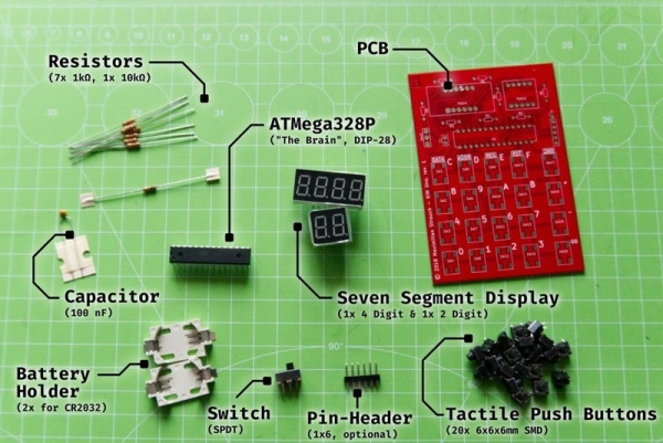
For an upcoming project I need a signal generator that produces a sine wave and a cosine wave*. The easiest way would be to buy a signal generator. I also could buy one of those amazing integrated circuits that Analog Devices makes and build a generator with that, but where is the fun in those options?
So I build one.
* (A cosine is just a sine wave shifted 90 degrees in phase.)
EDIT! I changed the schematic, take a look at new_schematic in step “The Hardware”
Supplies:
1 x STM32F407VGT development board (Ebay)
2 x LMH6645 Opamps or equivalent (Mouser, TME)
1 x LMH6643 (Dual) Opamps (Mouse, TME)
1 x Rotary Encoder + Switch (Ebay)
1 x 4 MHz crystal oscillator (Mouser, TME)
4 x NPN transistors, BC547 or equivalent (Mouser, TME)
1 x LM7805, LM7905 and LP2950-3.3 (Mouser, TME)
1 x Transformer 240V / 7.5V (or what is needed in your country)
1 x Small signal relays e.g. OMRON G6S-2 4.5V (Ebay)
1 x LCD ST7735 (Ebay)
1 x perf-board 100mm x 150mm (don’t remember where it came from)
handful or resistors and capacitors (see schematic)
PC with Linux, Windows or Apple
STM32IDE, STM32CubeMX, Notepad++ and what else you want
STLink-V2 or Segger J-Link
The STM32F407 datasheet
RM0090, the reference manual of the STM32F407
AN4013 cross reference timer overview
AN4031 using DMA in STM32F2.4.7
AN4566 extending DAC performance
much coffee and a lot of time
Step 1: Direct Digital Synthesis
The usual way to generate a waveform with a micro controller is to use an algorithm called Direct Digital Synthesis (DDS) and that is what is used here. I’ll try to explain how it works. (https://en.wikipedia.org/wiki/Direct_digital_synthesis)
Don’t let the name scare you off, once you see how it works it is simple.
(picture stolen from Wikipedia)
Step 2: DDS Explained
You can skip this Step if you are not interested in how DDS works, or if you already know. The basis is a table with the values of a sine wave, (see the picture). To produce the signal you need to take those values and feed them in the DAC. Shown in the table are 32 values (in the program for the micro controller we’ll use more)
We need a counter to select te wanted value from the table, a so called phase counter, let us use one counting from 0 to 65,535 (16 bits). This counter is coupled to the values in the table but after dividing the number by 2048. So to go from one value in the table to the next the counter needs to be increment by 2048.
(All numbers we use are integers, that means that there are no fractions, so 12/5=2 but also 2047/2048=0 2048/2048=1 2049/2048=1 and so on.)
Next we use a timer to increment this phase-counter let’s take a timer that does this 1,000,000 times per second (1 MHz). At each tick of this timer we increment the phase_counter with a certain step size e.g. 1 or 13 or 3465. Let’s keep it at 1. So after 1,000,000 / 65,536 ticks we have completed 1 full sine wave and we can do that 15 times in a second. That’s a sine wave with a frequency of 15 Hz. A rather low frequency.
Also remember that we divided the phase-counter by 2048 to select a value from the table, this means that each value was sent 2048 times to the DAC before we jumped to the next value. Let’s see what happens if we increase the step size from 1 to 16.
We now need just 65,536 / 16 = 4096 ticks to make a full sine wave, that is done in 1,000,000 / 4096 = 244 times a second, 244 Hz. Each value from the table now is send just 128 times to that DAC before the next one is selected.
So the step size determines the output frequency, and the formula to find this step size for a wanted frequency is this:
step size = frequency * 65,536 / 1,000,000
As a check, we want 1000 Hz: step size = 1000 * 65,536 / 1,000,000 = 65 (remember no fractions!) To go from 0 to 65,536 with increments of 65 we need 1008 ticks. We do 1,000,000 ticks per second so that can be done 1,000,000 / 1008 = 991 times per second. Not quite 1000 Hz but close enough. And still we send out each value 31 times before the next one.
How about 100 kHz? The step size = 100,000 * 65536 / 1,000,000 = 6553. We now race through the table in 10 steps, that means that of the 32 values in it only 10 are used, that will make the sine wave a lot less like a real sine wave.
So for high frequencies we will start to skip values in the sine wave table. That will produce a more distorted sine wave at the output of the DAC so we cannot go too far with that. Nyquist-Shannon may say that 2 values are enough for a sine wave, I think 7 or 8 values is a reasonable lower limit.
In the signal generator described here, the reference frequency is 7 MHz, the sine wave-table has values numbered from 0 to 1023 and the counter runs from 0 to 4,294,967,295. So the counter goes all the way from 0 to 4,294,967,295 and the sine wave values are numbered from 0 to 1023 we need to divide the counter by 4,194,304 to be able to get 1024 values from the table.
As said the counter is incremented 7,000,000 times per second (the reference) so if we increment the counter by 1 each time it will take 4,294,967,295 / 7,000,000 = 613 seconds to go one round trip. And in these two minutes! each value of the sine wave table will be send to the DAC 4,194,304 times.
One cycle per 2 minutes, that’s a very low frequency of 1.63 milli-Hertz. Not very useful unless you do seismographic work. If instead we increment the counter each time with a higher number, lets take a step size of 1000, we get 1.63 Hz, ah that’s better. With a step size of 613,566 the output frequency is 1000 Hz. That’s more like it.
Let’s go to 500 kHz, the step size is 500 * 613,566 = 306,783,378
But now it takes just 14 steps of the counter to go from 0 to 4,294,967,295 this means that there are just 14 values taken from the sine wave table to construct the sine wave at the DAC. As I think that 7 or 8 is the lower limit this fixes the maximum output frequency of the generator to around 1 MHz. Good enough for me, and as it turns out, also at the limit of the capabilities of the STM32F407.
So the value of the step size defines the output frequency via this formula:
step size = (frequency * 4294967296) / reference
As you see the numbers in this calculation get very big, so we need to use 64 bit variables. In the program I use even bigger numbers because I do not want to use floating point variables. I multiply both the frequency and the reference by 100 to be able to work with frequencies with 2 decimal digits.
I hope this explains the workings of a DDS.
Step 4: The Hardware
The hardware I decided to use a small development board with a STM32F407VGT, available on Ebay (and others) for less than 8 euro. This microcontroller has two Digital-Analog-Converters (DAC) and it can run at 168MHz. So it is cheap and fast, I like that.
Because the output of a microcontroller working on +3.3V is always positive and I want the signal to go positive as well as negative I also need two opamps to shift the signal down in voltage. To give the opamps a bit room for the outputs I decided to supply them with +5V and -5V.
So the powersupply has to deliver three voltages. It is also nice to be able to change the amplitude of the waves, one here with an attentuator made with four small signal relays in 16 steps of 3dB, from 0dB to -45dB.
The STM32F407 development board is cheap and that means they had to use less quality components. Most important here is the *stability* of the crystal oscillator. It turns out that it isn’t a crystal at all that is soldered on the board but a ceramic resonator. It should resonate at 8 MHz but the one I got actually worked at 7,936 MHz
This isn’t in itself a problem, I can adjust the value of the reference in the program to the actual frequency but the ceramic resonator is very sensitive for variations in temperature. So I chose to use an external crystal oscillator and removed the ceramic resonator (and 2 capacitors next to it) from the board.
The power supply: Mains voltage is brought down with a transformer of 7.5V eff, two diodes rectify the positive and negative phase and the rest is all the usual stuff, 2200uF capacitors, a 7805 and a 7905 for the +5v and -5V. I wasn’t to sure that the 3.3V linear regulator on the development board could supply enough current for what I had in mind so I took that off the board as well and used a LP2950-3v3 instead. In the end that probably wasn’t needed.
The opamps are LMH6645’s with a BW of 55 MHz (Texas Instuments), the offset voltage for them is generated with a pulse width signal coming from one of the many timers in the STM32F407.
A nice trick to increase the bandwidth of the DAC is to disable the internal buffer of the DAC and use the output *current* of the DAC to feed the opamp-amplifier. It is explained very well in application note AN4566 by STMicroElectronics.
The LCD display is a ST7735 controlled via SPI. The library for it was made by adapting a library from Olexandr Davydenko (https://github.com/o-m-d) who in turn build it standing on the shoulders of Dmitry LonelyWolf (https://github.com/LonelyWolf/stm32). The ST7735 is a colour display, but I use just two colours of it, white and blue. It is simply a small display I had lying around. To get it in the project box it wasn’t small enough, I had to cut off part of it and remove the SD-card socket.
Frequency, amplitude and offset is controlled with one rotary encoder, that is another consequence of wanting to build it in a rather small aluminium project box. But it works quite well. When you have more space on the frontpanel an extra rotary encoder for the amplitude would be nice.
The last thing to mention is the attenuator. It uses 4 small signal relays that switch in or out part of a logarithmic attentuator. (http://www.eijndhoven.net/jos/attenuator-calculator/index.html) You can go in sixteen 3dB steps from 0dB to -45dB. The impedance of the attenuator is 1k ohm. The original idea was to put a buffer between the attenuator and the output of the generator to lower the impedance to the usual 50 ohm but I don’t think I’ll do that, I like the output and the impedance as it is now.
It is all build on perfboard, no printed circuit was designed as I need just one signal generator.
EDIT: It turns out that I did not like it that the offset changed with the attenuator. So It did build the buffer. In the new_schematic it is added to the signal generator. The pwm-generated offset voltage is now rerouted to the output buffers and the offset for the first opamps (amplifier) is made with a 10 turn, 10k trimmer.
The pin numbers for the LMH6643 are wrong, it is a dual opamp, I couldn’t find the right layout in Kicad, check it before you start soldering.
Step 5: Pictures of Building and Testing
I always forget to make pictures during the build, this is the rest of what I have. Notice that I needed to cut of part of the LCD to make it fit in the project box.
Step 6: The Code
INIT
As I was trying to get the most performance from the micro controller I discovered CCMRAM, core coupled memory. This memory is directly coupled to the processing core and could be used to speed up execution of your code. Unfortunately in the STM32F4 series it is only coupled to the D-bus. This means you cannot use it for code. And even more unfortunate, it cannot be used by the DMA controller! But I had changed things in the linker script to use this CCMRAM so I needed to tell the linker not to put the dac-buffers in CCMRAM, but in normal RAM. If you do not change the linker scripts, leave out the __attribute__((section(“ram”))). It didn’t speed up anything anyway.
From the line
uint32_t const reference = 699994750; //~7 MHz
you can tell that the crystal oscillator does not generate the exact 4 MHz that it should, it actually is 3999970 Hz, thirty Hz too low. That doesn’t matter, the reference is adjusted accordingly.
To transport the data from the arrays to the DAC, DMA is used. Here the STM32F407 DMA shines, you can make it use double buffer mode. That means that while the DMA is busy sending the contents of one buffer to the DAC, the processor can work on the other buffer, undisturbed. In the DMA-IRQ routine we’ll see how this is done.
Timer3 has Channel4 connected to GPIOB_1 port to generate a PWM signal that is used to make the offset voltage for the opamps.
Timer4 is connected to the Rotary Encoder, as I’m only interested in whether it is turned up of down, the actual value of the counter is set to 100, if it is higher than 100 it is turned up, if lower it is turned down. After registrating this, the counter is again reset too 100.
Timer7 is responsible for the timeout after you stop using the Rotary Encoder.
Timer8 is the most important one, it generates the ticks for the DMA, at each tick the DMA has to send the next value in one of its buffers to the DAC. Experimentally I have found that the maximum speed at which this still works reliably is 7 MHz. If you go higher the first thing you will notice is that the output signal isn’t stable when you use the Rotary Encoder, and if you go even higher the DAC starts to skip values send to it. ST claims in application note AN4566 that it should be possible to get the DAC to accept data at a rate of 10.5 MHz (when the micro controller runs at 168MHz) but I could not get it higher than this 7MHz.
This instructable is designed to help you build a simple game buzzer system for classroom review games. In this Instructable, you will create simple cardboard switches that will work with a Makey Makey and will be coded using Scratch.
Supplies:
4 Pieces of Cardboard (3 x 3 inches)
4 pieces of Tin Foil Tape cut to 3 x 3 inches
4 Pieces of Foam
2 Rubber Bands
Colored Paper or Tape
1 Makey Makey
1 Computer
Step 1: Prepping Your Supplies
Take your tin foil tap and put it on 1 side of each of the pieces of cardboard.
On the opposite side from the tin foil, attach your colored paper or tape.
Step 2: Make Your Switch Sandwich
Add two pieces of foam and place them on the tin foil tape side of 1 piece of cardboard.
Make sure the foam is spaced out on the ends of the cardboard to leave space in the middle.
Take the piece of cardboard that has the colored paper on it and place the tin foil tape side down onto of the pieces of foam.
Repeat Steps 1-3 for the other two pieces of cardboard.
Take your rubber bands and wrap it around the cardboard sandwich.
* Make sure that rubber band it not too tight around the cardboard sandwich and that the space is still preserved in the center.
Step 3: Connect Your Makey Makey
Take two alligator clips and attach one to each piece of cardboard of the cardboard sandwich. One on the top and one on the bottom. Make sure that the alligator clip is touching the tin foil tape.
Repeat for the other cardboard sandwich.
Take one cardboard sandwich. Take the open end of the alligator clip and put one into the Up Arrow spot on the Makey Makey and take the other alligator clip and attach it to the earth.
Now, take the other cardboard sandwich. Take the open end of the alligator clip and put one into the Space spot on the Makey Makey and take the other alligator clip and attach it to the earth.
Connect the USB Port on your Makey Makey to your computer.
I have been experimenting using different ESP32 development boards, recently I ordered of the TTGO T-Beam variety which come with a Battery socket to add your own 18650 Lipo, this really takes some of the power regulation complexity out of building a small robot, as it has the battery and charger circuit in place already.
However to directly drive something from this board it needed something low powered, so I decided to add some continuous rotation servos I have had for a while.
The ESP32 board I used here has a lot of functionality including Lora radio and GPS, which may be useful in the future, but you can get ESP32 boards without these extras which make the board a bit smaller and still come with the 18650 battery holder.
So let’s start talking about the build.
Supplies:
4 x Continuous rotation Servos
4 x Wheels that fit on the Servos
1 x strip of 5 x Neopixels if you want to add them.
1 x ESP32 with ideally built in rechargeable battery, or an ESP32 with an external battery.
I bought mine from Lilygo Aliexpress which shipped way quicker than I expected the one i used can be found here https://www.aliexpress.com/item/32967228739.html?spm=a2g0s.9042311.0.0.206f4c4dXaqAU9
1 x Small piece of perspex, that can be cut and drilled to form chassis.
1 x small piece of veroboard
some wire, and I used a mini jst socket as a connector, but this could just be soldered.
4 x Servo Headers, so you can just plug the servos in to the connector veroboard
Some plastic circuit board standoffs.
Step 1: Building the Chassis
I wanted a real basic chassis that any body could make using some perspex or plastic, even an old plastic lunch box or takeaway could potentially be used.
I cut a piece of perspex out a little wider than the ESP32 board, but about the same length, I then marked where I would want to add the 4 holes to mount the ESP32 using circuit board standoffs.
Attaching the Servos
I positioned the Servos so that they were all orientated the same way, so when wired up they would drive the same direction. I used some plastic glue to put these in place and added some more standoffs to aid in holding them.
I drilled holes for the servos wires to go through the base of the chassis so they could be plugged into the small veroboard I used which I will detail later on.
I bundled up the servo excess wiring the best I could and used a couple of small cable ties to hold them in position.
Covering it all up
As a final step I covered it all in with a piece of perspex the same size as the first piece I cut. I drilled holes for the extra standoffs and added standoff screws to hold it all in place.
I was surprise how light this once together was in weight, much lighter than my motor based one I made the previous week.
Step 2: Making a Custom Veroboard
I wanted to make a small board that would allow me to plug my ESP32 into the board and be easy to remove when needed. So I created it as show in the photographs, I added some header pins so I could plug in the Servos and later a neopixel strip.
I also added 2 small jst sockets I had some of so I could use these for power from the ESP32 and also to provide the Servo signal connections.
I cut one of the copper tracks on the underside of the board, so that the signal pin to each servo was different, I then used a small wire connector to move it by the wire by one track so the two jst pins would connect with one side or the other.
As there were two servos on each side of the vehicle I used the board to connect the two servos each side to each other, so i could run the left hand side servos or right hand side ones with a single servo connection, to each side. All I am doing here is connecting the connections together for each side to simplify the amount of wiring needed.
I allowed the Vcc and GND connection to connect all the way across the veroboard via the copper tracks, however I cut the signal line so I could control the different sides I wanted to drive independently.
Step 3: The Wiring
To wiring diagram here shows the connections and how with as few wires as possible I connected the Servos and Neopixel strip.
Step 4: Putting It All Together
Once I had everything wired I fitted the custom veroboard, and added the ESP32 to the chassis, it all fitted well.
The wiring was mostly concealed and hidden and sides could easily be added and a top to fully enclose the ESP32.
Step 5: Controlling and Testing
I wanted some simple controls and found that at the website https://randomnerdtutorials.com/ they provided a good example how to run a webserver and have controls displayed so you could get the robot car to drive around. I modified the example to use servos instead of motors, and added code to use the neopixel strip, as well as to display on the Oled screen the IP address I would need to connect to so I could control the robot.
Step 6: Code for the ESP32
Here I attach the code which can be modified for your own purposes, full credit goes to randomnerdtutorials which form the basis of what I have here. I would highly recommend buying the course they have on the ESP32, it takes you through lots of the complexities using the ESP32, with some really good example projects.
I hope this has been useful to others trying to get up to speed in using the ESP32 for robotics.
You can follow me on twitter to see more of what I do here @elliotpittam or you can visit my website for other information. www.inventar.tech
Fun display of current and upcoming Splatoon 2 stages in Turf War and Ranked games, Ranked game type, and Salmon Run schedule using an Adafruit PyPortal. Cycle through the schedule by pressing on the touch screen. Backgrounds are randomly cycled for eye candy. The optional Amiibo stand is for Amiibotronics that spin Amiibos toward the screen when there are schedule changes.
This project is really easy if you just want to display the schedule on a PyPortal and use what I have. Basically you just have to update the configuration files for your network settings, Adafruit IO account information, and time zone.
The project gets slightly more involved if you want to customize further depending on how well you are with image programs and Python programming.
Adding the Amiibo animation is optional and will require quite a bit more of work with soldering and 3d printing.
Caveat
The PyPortal is not as fast as your 1ms HDMI gaming monitor. The display takes a few seconds to finish drawing everything to the screen.
Download the SplatSchedule project from GitHub. Create a secrets.py in the src/conf directory with your information using the example in src/conf directory. Update application_configuration.py in the same folder.
Create a backgrounds directory on the micro SD card at its root. Copy all bmp files from the project images directory into the backgrounds directory you just made. Insert the micro SD card into the PyPortal.
Install the SplatSchedule_[date].uf2 file from the firmware folder to the PyPortal by pressing the reset button on the back of the PyPortal twice quickly to open the Boot drive. Then copy the file over. The PyPortal will automatically reboot when the file is done copying. This firmware is CircuitPython 4.0.1 with the required Adafruit libraries built in.
Copy all files from the src directory onto your PyPortal and you should be good to go. The PyPortal should automatically reboot itself and startup.
The following are a quick explanation of the configuration files.
secrets.py – Each configuration should be self-explanatory. Replace SSID with your WiFi’s SSID and so forth. You will need to grab your time zone from http://worldtimeapi.org/timezones, eg. my time zone is Pacific/Honolulu.
# This file is where you keep secret settings, passwords, and tokens!
# If you put them in the code you risk committing that info or sharing it
# which would be not great. So, instead, keep it all in this one file and
# keep it a secret.

secrets = {
    'ssid': 'SSID',             # Keep the two '' quotes around the name
    'password': 'PWD',  # Keep the two '' quotes around password
    'timezone': "TIMEZONE",  # <a href="http://worldtimeapi.org/timezones" target="_blank">http://worldtimeapi.org/timezones</a>
    'aio_username': 'AIO_USERNAME',
    'aio_key': 'AIO_KEY',
    }
application_configuration.py – You only really need to update time_adjust to quickly get up and running. I didn’t figure out a way to get that number timezone setting from secrets.py so you will need convert your time zone adjustment into seconds. The rest of the settings should be self-explanatory.
configuration = {
    'battle_schedule_url': 'https://splatoon2.ink/data/schedules.json',
    'salmon_schedule_url': 'https://splatoon2.ink/data/coop-schedules.json',

    'time_service': 'https://io.adafruit.com/api/v2/%s/integrations/time/strftime?x-aio-key=%s',
    'time_service_strftime': '&fmt=%25Y-%25m-%25d+%25H%3A%25M%3A%25S.%25L+%25j+%25u+%25z+%25Z',
    # Adafruit IO strftime is %Y-%m-%d %H:%M:%S.%L %j %u %z %Z see http://strftime.net/ for decoding details
    # See https://apidock.com/ruby/DateTime/strftime for full options

    'time_adjust': -36000,  # hours in seconds
    'touchscreen_touch_throttle': 2,
    'sd_mount_directory': '/sd',
    'background_images_directory': '/sd/backgrounds/',
    'background_timeout': 900,  # 900 = 15 minutes
    'schedule_change_timeout': 180,  # 180 = 3 minutes
    'schedule_refresh': 43200,  # 43200 = 12 hours

    # If you built the turntable stage, set to True
    'enable_turntable': False,

    # The follow are optional and used for testing and debuggin
    # 'debug': False,
    # 'disable_wifi': False,
    # 'use_test_files': False,
    # 'test_battle_schedule_file': '/test_battle_schedule.json',
    # 'test_salmon_schedule_file': '/test_salmon_schedule.json'
    }
That’s all there is to getting a PyPortal Splatoon 2 Schedule display. Read on if you want to customize a background and/or tweak text placement.
Step 2: Background Customization
Included in the SplatSchedule project is a GIMP project file used to create the backgrounds. Use this as an example if you like using GIMP. Or use your favorite image editor to make backgrounds. Follow some of the guidelines below to help you make backgrounds that are displayable.
The stage backgrounds were grabbed from Inkipedia.
As mentioned earlier, the PyPortal is not fast at rendering the display. To help cut down on what the PyPortal has to process, place static text on the background.
Backgrounds must be 320×240 pixels in size and in bitmap format. I saved the backgrounds in 24-bit format as 16-bit looked horrible and 32-bit had a blue tinge to them.
That is pretty much it for backgrounds. The next step describes text font and placement.
Try not to use more than 3 fonts for the issues noted below.
Use your image editor to help you find the coordinates of where you want to place text so that you are not just wildly guessing. Usually the pointer tool of image editing software will have its x and y coordinates displayed somewhere in the editor, most of the time in the status bar.
Issues
The more fonts you use, the longer the PyPortal takes to startup as all the fonts used are loaded up during setup.
Bitmap fonts take up lots of space and will eat into PyPortal’s onboard storage space.
You can create a fonts directory on the micro SD card and point there (eg. /sd/fonts/), but I’ve run into a weird problem where the same font will run from the onboard storage but not work from the micro SD card. I could not resolve what the issue was about loading from an SD card.
Step 4: Read on to Build Amiibtronics Display
The next bunch of steps are for building the DJ Turntable Amiibotronic stage display.
You can stop here if you just want the PyPortal for displaying the Splatoon 2 schedules.
Step 5: PyPortal I2C 3.3V
I found the onboard Real Time Clock (RTC) stops ticking if you connect a 5V I2C device. I think this is due to the RTC has pull-ups to 3.3V. Then adding a 5V I2C device that has its own pull-ups to 5V throws off the RTC.
There is a jumper near the ports on the side of the PyPortal to select the voltage output ports. See Adafruit Pinouts for reference.
Cut/scrape away the little itty bitty trace connecting the center pad to the 5V pad. ***Important*** Cut/scrape away from the ribbon cable!
Use a multi-meter to check that there is no continuity between the center pad and 5V pad. Also check that the port voltage pin has no continuity to the 5V pad.
Solder a little solder bridge from the center pad to the 3V pad.
Use a multi-meter to check the continuity of the center pad to the 3V pad. Check that there is no inadvertent connection with the 5V pad too.
Step 6: Power Connector – Wiring PyPortal
We will power the PyPortal by connecting directly to the 5V bus instead of using the PyPortal’s micro USB port.
The wire that comes with the JST RCY connector is too big to squeeze through the Adafruit PyPortal enclosure. You will need to solder smaller 24AWG wire to the PyPortal and then to the JST RCY connector. Use the conventional colors of red for positive and black for ground for the wires.
Strip and tin the ends of the 24AWG wires. Snip the end to just the size of the 5V solder pad (the pad we just disconnected in the previous step).
Tin the 5V pad and solder the red wire to the pad. Then carefully bend the wire to go between the I2C port and D3 port.
Tin the ground pin of the D3 port (the top pin) and solder the black wire to it. Bend this wire to follow the red wire.
Step 7: Power Connector – Adding Connector End
Trim the wires attached to the male end of the JST RCY to a reasonable length, like an inch or two. I chose the male end to make the connector consistent with the side ports.
Slip on head shrink tubing on the wires before solder splicing them together.
Solder the connector wires to the wires we soldered in the previous step.
Shrink the tubing into place.
Step 8: Disconnect Onboard Speaker
We will connect external speakers and need to disconnect the onboard speaker. See Speaker and Speaker Connector for reference.
There are two solder pads connected by an itty bitty trace to the left of the onboard speaker. Cut/scrape away that tiny little trace.
Use a multi-meter to check that the two pads are no longer connected to eachother.
If you want to make the digital compass portable, you may consider get a battery holder.
Any 3V battery holder with JST connector should be ok. The battery can be CR2032, 2 x AAA batteries, 2 x AA batteries, etc.
Step 3: Optional: 3D Printed Cover
I feel direct view the SMD LED light is not so comfort, so I have made a 3D printed cover diffuse the light and make every LED like a perfect square pixel :>
If you also like the pixels, you can download and print the cover here:
micro:bit have a magnetic field sensor, just like a normal compass needle, it can sense the magnetic field produced inside Earth. micro:bit library translate the field value into 360 degrees relative to north.
Output
micro:bit have 5 x 5 LED matrix, it is good enough to show an arrow in 8 directions. (North, NE, East, SE, South, SW, West, NW)
Please reminded that the magnetic field sensor and the LED are placed on different side of the PCB. So when you look at the LED side the magnetic field reading is flipped. Or you can treat the reading is counter-clockwise start from North.
Step 6: Angle Mapping
The input is a 360 degrees value and the output is 8 directions arrow, here is the angle mapping:
 23 -  68 NW
 68 - 113 West
113 - 158 SW
158 - 203 South
203 - 248 SE
248 - 293 East
293 - 338 NE
Others    North
Step 7: MakeCode
Here is my sample block code:
https://makecode.microbit.org/_RfA4jH2Rae78
Simply download and copy to micro:bit drive to run.
If you are not yet familiar with using micro:bit please read the official quick start guide first:
The KIM Uno is a portable, software defined dev kit for (retro) microprocessors. But let me introduce the idea of it by going back in time:
Back in late 2018 it came to my mind, that I wanted to build a small portable microprocessor dev kit, just like the famous KIM-1 from MOS Technology, Inc. and designed by Chuck Peddle who was also involved in creating the 6502 CPU.
But building a “bare-bone” dev kit with discrete logic components was no option since it needed a big power supply (since those ancient devices tend to take some serious current) and also the development would be very time intensive. And I want it now!
Therefore, I designed the KIM Uno as a portable device, which fits in one hand and is powered by two CR2032 batteries. It uses the ATMega328p (“Arduino”) microcontroller running at 8 MHz to emulate (or simulate) a desired CPU. This architecture also makes sure, that the emulated CPUs are interchangeable to anything which fits inside the microcontroller’s flash memory. So it is a multi-purpose device.
By coincidence I later watched a really good talk – called The Ultimate Apollo Guidance Computer Talk (34C3) – on YouTube where “One Instruction Set Computers” or OISCs are mentioned. I did not know about them and found this as the perfect candidate to implement it.
The KIM Uno emulates a CPU with just one instruction: subleq – subtract and branch if less than or equal to zero.
If you follow along with me through this Instructable, you can build your own KIM Uno in no time. And the best part – beside the fact that you can modify it to your taste – is, that it only costs 4,75 € to make (as of end 2018).
One hint: there is a Git repository which contains all the files provided by the different steps of this instructable. In case you want to modify some resources and share them with us all you can make a PR. But you can also download all files at once there. Simply to to https://github.com/maxstrauch/kim-uno. Thanks!
There is another pretty interesting project, called the same (KIM Uno), which does a real replica of the 6502 KIM Uno. Check it out here. The creator even sells the kit. So if you are interested in 6502 and like this project, you should take a look there!
Step 1: Sourcing the PCB
As you can see, I used the opportunity to design a PCB and let it be professionally made. Since manufacturing it externally and shipping it to you will take a lot of time (depending on where you are in the world ), getting it ordered it is the first step. We can then continue with the other steps while the PCB is made and shipped to you.
I ordered my PCBs in China at PCBWay for just $5. I don’t get any benefit for presenting PCBWay as my goto manufacturer for PCBs, it’s just that it worked fine for me and might also work fine for you. But you can order them at any other place like JLCPCB, OSH Park or any local PCB company.
But if you are willing to order them at PCBWay you can download the attached ZIP file “kim-uno-rev1_2018-12-12_gerbers.zip” and upload it directly to PCBWay without any change. This is the original file I used to order the PCBs you can see in the images.
If you are ordering them from an other manufacturer you might need to re-export them from the original KiCad sources, because I generated them with the specifications from PCBWay you can find here. For the original KiCad sources, download “kim-uno-kicad-sources.zip” and extract it.
But there is even a second way: if you don’t want to order the PCB, you can build your own version using perfboard or even a breadboard.
Anyway: since the PCBs are now on the way, we can focus on the other parts! Come, follow me.
Step 2: Sourcing the Components
Now you need to get the components. For this you’ll find an overview image of all components and quantities you need, attached to this step as well as a BOM (bill of materials).
The BOM contains links to eBay. Although those offers might be closed when you read this, you can use it as a starting point. The used components are pretty standard.
In the following I’ll explain to you all the needed components:
7x 1 kΩ resistors for the seven segment displays. You can reduce the value (e.g. to 470 Ω) to make them shine brighter, but reduce it not too much otherwise the LEDs will die or the battery is drained very quickly. I found that this value works for me
1x 10 kΩ as a pull-up resistor for the RESET line of the microcontroller
1x 100nF capacitor to smooth out any voltage spikes (which should not happen since we are using batteries, right, but for good measure …)
1x ATMega328P in the DIP-28 package (usually named ATMega328P-PU)
1x the main PCB – see the previous step; either ordered or built by yourself
2x CR2032 battery holders
1x SPDT (single pole, double throw) switch which basically has three contacts and in every of its two states (either on or off) it connects two contacts
20x tactile push buttons for the keyboard. To use the backside of the PCB I used SMD tactile push buttons (the standard 6x6x6 mm ones) – they are pretty easy to solder as you will see
OPTIONAL: 1x 1×6 pin header for connecting the programmer, but this is optional as you will see later
1x seven segment display with 4 digits and 1x seven segment display with 2 digits – the board will take only 0.36 inch (9,14 mm) elements with common anode wiring. Both requirements are important in order to get a working unit. But also this type of seven segment display are very common
Attached to this step you can find the file “component-datasheets.zip” which contains more precise information on dimensions and types of the used components. But most of the components are very standard and can be sourced easily for little money.
Now you need to wait until you have all components ready to continue to soldering. During this time you can already jump to the end and read a little bit about using the KIM Uno if you like.
Step 3: Soldering Tool Overview
For soldering and building the KIM Uno you need the tools shown by the images:
Wire cutter (to cut the end of the component wires)
Flat pliers
Pair of tweezers
(decent) Solder which is not to thick – I use 0.56 mm solder
A soldering iron – you don’t need a high-end soldering iron (because we are also not doing rocket science here) – I use the Ersa FineTip 260 for a long time now and it is really good
A flux pen: adding flux to the components and pads makes it so much more easier to solder them since the solder then “flows” by its own to the right place*
Optionally: a sponge (from metalwool) for your soldering iron
To later program the KIM Uno you’ll also need:
a computer with the AVR-GCC toolchain and avrdude to upload the firmware
an ISP (programmer) – as you can see on the image I’m using my Arduino Uno as an ISP with a special sketch – so no need to buy any fancy hardware
* some guidance by humans needed
Are you ready? In the next step we are going to start assembling the KIM Uno.
Step 4: Soldering #1: Adding Resistors and Capacitors
You should always work from the smallest (in terms of component height) components first, to the highest components last. Therefore, we start by adding the resistors and bending over the legs at the back so that the resistors are easy to solder and stay in place. Afterwards cut the long wires.
Also, not shown in the images, add the small 100 nF capacitor the same way.
One tip: keep those wire legs in a small container, they sometimes come in handy.
What is ultimate? Infinite RGB? How about a cool LCD touchscreen? Maybe even some completely unnecessary wifi capabilities? How about all of them- in a gumball machine. DFRobot reached out to me to create a project that uses their 2.8″ TFT screen, so I made the most amazing gumball machine ever (of course).
As usual, almost everything that’s more complex than making a few simple connections and a basic box needed a design in Fusion 360. I started out by sketching what I wanted the machine to look like. It needed to be tall, have enough room for all of the electronics, and also be able to support the weight of 12lbs of gumballs. So then I tried to make a simple and elegant dispensing mechanism. It had to only dispense one gumball at a time, not get jammed, and not let more than one gumball fall through what it turns. I came to the realization that all I needed was a simple wheel with 4 holes, and that the dispensing hole would have a cover on the top of it to stop excess gumballs from falling through. After my design was finished I exported all of the 3d-printable parts and generated toolpaths for CNC routing the housing. Thingiverse link
Step 2: Housing and Fabrication
I started by gathering the dimensions for the gumball machine’s legs and then sketching them out on a huge sheet of plywood. Then I took a jigsaw and cut the four legs out. I also cut out the main housing from plywood with my CNC router. Then I drilled holes into everything and painted it red. The LED strip got glued onto the bottom plate so it could cast a nice glow onto the machine’s stand below.
Step 3: Webpage
In order for users to interact with the gumball machine there needs to be an easy interface. I chose to create a simple webpage that lets users dispense gumballs and change the LEDs’ color. After an action happens the webpage POSTs data to a custom Node.js webserver via AJAX.
Step 4: Webserver
I needed a webserver to act as an intermediary between users on the webpage and the gumball machine. Therefore, I decided to use Node.js to both send and receive data. Users send a POST request to control LED color and dispense. Then the ESP8266 sends a GET request to get the status of the machine. And what happens if someone keeps clicking “dispense”? The server keeps track of all the IPs that have clicked the dispense button and blocks them from dispensing twice.
Step 5: Electronics
A TFT screen takes a lot of processing power to drive, so I had to choose a fast and powerful board, leading me to use the Teensy 3.5. But now you might be thinking to yourself: “How does a Teensy use Wifi?” That was a very hard problem for me to solve. I needed to get the Teensy to listen to a local server for changes made by users. Then it dawned on me to just use an ESP8266 to check the server and then “talk” to the Teensy via Serial, which made it a lot easier.
Step 6: Software
The Teensy runs a simple script that first loads the image from the SD card and displays it onscreen. Then it checks serial data to see if it needs to change the color of the LEDs or dispense.
Step 7: Usage
Using the gumball machine is pretty simple: just go to the webpage and click the “dispense” button. Or, better yet, just go up and push the button. Then just reach in and grab your rightful prize.
In this tutorial we are going to show you how to make an interactive sound wave print within a picture frame, so you can see and hear your favourite song at the same time! When you touch the print through the glass of the frame, it will play the song shown in the sound wave image. Printed Sensors behind the print act as a proximity sensor and are connected to a Touch Board and speaker behind the frame.
First, you need to create your sound wave print. We used this website here to generate a sound wave from a song. Simply upload the song you want to use, download the generated wave and design your sound wave print. We recommend printing the sound wave on card instead of paper, so the sensor pattern doesn’t show through.
Step 4: Upload the Code and the Song
If you haven’t set up your Touch Board yet, do so now by following this tutorial here .
In this project, we used our Proximity_MP3 sketch. In order to detect touch through glass and paper, the sensors of the Touch Board need to be more sensitive. Therefore, the Proximity_MP3 code is more suitable than the Touch_MP3 code. Simply open the Proximity_MP3 sketch, which is located under File > Sketchbook > Touch Board Examples > Proximity_MP3 and hit upload! You also need to upload your song to the Touch Board. Read this tutorial here if you haven’t changed the sounds on the Touch Board before. We will use electrode E0 to trigger the song, so upload your chosen song named TRACK000.mp3 to the SD card.
Step 5: Prepare the Printed Sensors
Attach a strip of the Printed Sensors to the back of the picture frame, where we’ll connect it to the Touch Board. Cables aren’t necessary, as the Printed Sensors can be bent. Carefully cut away part of the Printed Sensor so you are left with a reversed L-shaped sensor. Make sure that the long part of the sensor has an access node, as this is where you are going to connect the board.
Step 6: Assemble Sound Wave Print Frame and Sensor
Now it’s time to assemble! Firstly, place the sound wave print inside the picture frame. Now, add the Printed Sensor behind it, the pattern facing the same way as the print, and make sure the strip extends beyond the frame. Secure the frame backing in place, and bend the Printed Sensor down. Stick it down with Blue Tack, or double-sided tape.
Step 7: Attach the Touch Board and Cold Solder
This project only uses one electrode – we used E0. Before you can attach the Touch Board to the frame, you need to make sure that the other electrodes won’t interfere. Do this by simply adding masking tape behind the other, unused electrodes.
Attach some Blue Tack or double-sided tape to the back of the Touch Board and place it so that electrode E0 lies over the access node of the Printed Sensor. Cold solder the electrode E0 to the Printed Sensor with Electric Paint. If you haven’t cold soldered before, have a look at this tutorial here . Finally, securely attach the speakers and connect the board to a power source.
Step 8: Touch the Sound Wave Print
Now, when you touch the sound wave in your print, it will play your song! Well done, you have your very own interactive sound wave print.
If you are having difficulties playing the track when touching the picture, try playing around with the thresholds of the sensors, as described in this tutorial here . We’d love to see your creations, so send us your images either at info@bareconductive.com, or send us your images on Instagram or Twitter .
After completing my GSM Home Alarm V1.0 and some time of using, I decided to make some modifications.
In the hardware the main changes are the replacement of the ultrasonic sensor and the introduction of a keypad. On the software, I change the SMS notification by e-mail. Also I decided to scale down the circuit and design and 3D print a box for the circuit.
The FireBeetle ESP32 IOT Microcontroller will be the brain of this project. The big advantage is that you can get WIFI and Battery management in one very small footprint. It is powered directly from the USB port (+5V) but I also added a battery as backup power (this last one is opcional).
The keypad is connected from pin D2 to pin D8. The led is connected to pin MOSI/IO19. The PIR Sensor signal pin is connected in pin A1/IO39.
A +5V power supply (normal smartphone wall adapter) needs to be connected to the nano USB connector. One +3.7V battery can be also added as backup power.
Step 3: Pushing Box
During this project I discovered this IOT service that allows you to setup several notifications.
5- Configure the email that will receive the notification.
6 – Go to “My Scenarios”
7 – Press “Test”.
8 – If everything is ok, you should get an email in you inbox.
Step 4: Code
For you to use my code, some changes are necessary.
Define your WIFI network name and password.
Copy the DEVID from “My Scenarios” on Pushingbox and paste it in the code.
Upload and open a Serial Monitor window to check if everything is working. For activating the system just press “1234”, my default password, and the alarm will be armed in 8s (this can be also changed in the code).
The iconic scene from Jurassic Park came in the car where the glass of water resonated with the approaching footsteps of the T-Rex (spoiler). The original scene was done according to web blogs by someone carefully boinging a musical string attached to the support for the glass–they had tried other methods but this was the only one they could get to really work. There you are perched with your glass on the beach with your solar charging bluetooth coaster about to dramatize the approach of humanoid behemoths on your piece of sand (gargantuan mortals seem to abound these days and with cheaply constructed floors maybe this device is unnecessary but getting water to shake with sound is difficult in small packages… ) so you flip on some base heavy sound cloud channel and watch in horror as the water surface stirs to the beat! Well, underwhelming to be sure so you just relax and enjoy the sound from one of many bluetooth speakers that now fill up the world.
This is a simple project involving a transducer–essentially the guts of a speaker, a lipo-battery, a bluetooth module and some solar cells. It works by transmitting sound waves to anything that touches the active plate on the surface of the coaster. Glasses (beer, martini, highball) work well–the volume declining (liquid and auditory) while you sip. Solar charging is on the bottom side and when you flip it a tilt switch turns off the device.
Step 1: Gather Your Materials
All the parts are pretty cheap–about $25. The main Bluetooth board is off the web and they all have issues…but generally its performed well. The charger board for the solar panels is a TP4056—cheap and efficient. I did not include a blocking diode in the circuit and I’m not sure if there is one in the charger but you can easily do it. Go for big on the Lipo battery so you can play it for a couple hours and it should take a good bite out of the sun when charging. The transducer is available from a couple sources some have wires attached and some don’t–as soon as you wire it up protect the connections with hot glue because they are quite fragile. The Jurassic Park front cover is a printed aluminum plate about 5 x 5 off a web picture done by mail order–really easy.
1. KNACRO 3W+3W Wireless Bluetooth 4.0 Audio Receiver Steady Digital Amplifier Board $12.00 on AMAZON
2. DAOKI 10PCS PFM Control DC-DC Converter Step Up Boost Module 600MA USB Charger 0.9V-5V to 5V
3. XCSOURCE 5 pcs 1A 5V Micro USB TP4056 Lithium Battery Power Charger Board Module TE420
4. Lithium Ion Polymer Battery – 3.7v 1200mAh Adafruit or Amazon
5. Bone Conductor Transducer with Wires – 8 Ohm 1 Watt Adafruit or SparkFun
6. uxcell 5Pcs 5.5V 60mA Poly Mini Solar Cell Panel Module Charger 90mm x 30mm Amazon
7. Tilt sensor–Amazon
8. Epoxy–big box store the stuff to make bar tops with.
9. Aluminum print–Collage.com
Step 2: Wire It
The fritzing diagram has all the connections for the components. There is no on/off switch. When the Solar Coaster is face up the tilt switch turns on and sends power to 5 volt boost circuit which powers the Bluetooth and Amp. When the Solar Coaster is flipped over the tilt switch cuts off power and the solar cells just power the charge controller and battery. The elements are just wired up on the back of the Aluminum plate and then hot glued down for stability when the epoxy goes on. The transducer is not connected up until after the epoxy pour so leaves the wires for this hanging out in the center.
Step 3: Build It
Cut out a window in your aluminum plate that fits the transducer. Build a dam around the plate with cardboard or whatever you want to seal in your project for the epoxy pour. Hot glue works well for sealing these temporary partitions. The center hole where your transducer will go also has to has its own dam–this can be done with even packing tape. Make a hole through the dam where you can feed the connecting wires from the rest of the circuit. The tilt switch is placed through a small drilled hole in the plate to stick out on the side of the logo. The big box store epoxy is pretty easy to pour–you just need enough to cover your components–you don’t have to cover the solar cells as they have their own epoxy cover thats probably more UV resistant anyway–just enough to attach them. I contact cemented some cabinet rubber runner material over the epoxy but you can leave it open if you like the circuit look. Finishing the transducer installation takes some finesse. There is a plate on the top side that must be above the surrounding stratum to provide contact with the glass bottom. Too high and the glass will want to tilt constantly–too low and no sound. Also you want a spongy glue contact to mount it to the Solar Coaster to minimize transferring vibrations to the coaster alone without the glass–I used silicon which absorbs most of the vibrations.
Step 4: Using It
The Bluetooth dongle starts to connect as soon as you flip it over. You know the drill for connecting it to your phone or Alexa. To use–get on an airplane and fly to a warm beach with really good sand and leave it charging for a time while you swim in the ocean. Then as the sun sets place a cold beer in a glass and set it on the Solar Coaster and totally ignore the whiny Taylor Swift voice coming from it and enjoy the view.
Because of the remake of the animation and movie of Space Battleship Yamato, in addition to the attractive design of Bandai model. It make me interest to build this space battleship model again. Bandai not mention its scale, maybe ~1:2500 by estimation.
Step 1: Start
Design the assemble Sequence and Drill Holes for Those Lighted Parts
Step 2: Making of Wave Motion Engine
– The main engine is built by a mini DC motor and surround with 0603 LEDs, the slow motion rotation and LED effect is control by the microcontroller.
Step 3: Microcontrollers
– The main Microcontroller of this project is using 8pino, which is the world smallest Adafruit Trinket compatible controller in 2014. Seems it still the one now.
– Minor modification with IC socket to add main LED there – 100mm circular platform purchased from Tokyu Hands, embedded with LED try to build effect of star in dark sky, the side holes were used for soft switches.
Step 4: LEDs
– Light effect to be added to primary and secondary bridge, captain’s room, ship sides, space fighters depot entrance, main and auxiliary engine and wave motion gun
Step 5: Battleship Interior and Body
– Basically follow the wiring diagram. Most parts without glue together for future maintenance if any.
– Main color is dark grey, german grey and red
Step 6: Assemble and Test
– Total length is ~12.5 cm
Step 7: Making of Planets
– The planet earth (before and after attack) and moon are make by ping pong ball with paper clay


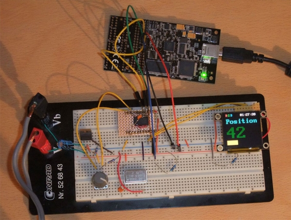
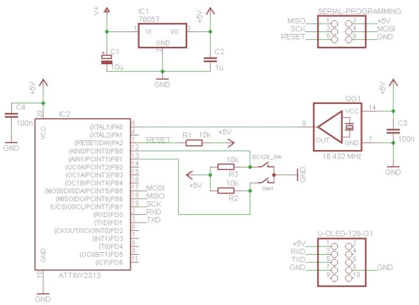
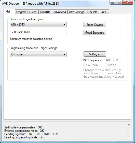

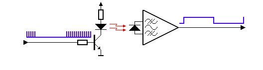
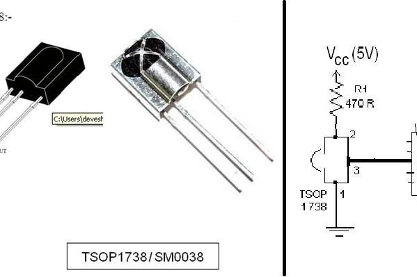
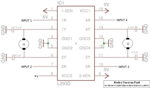
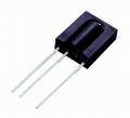


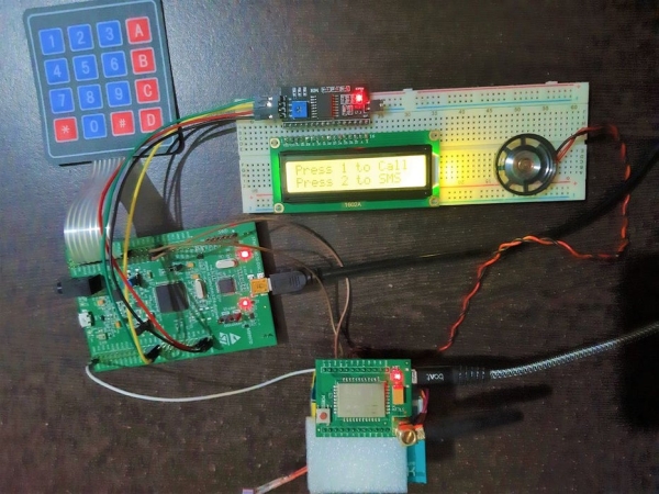
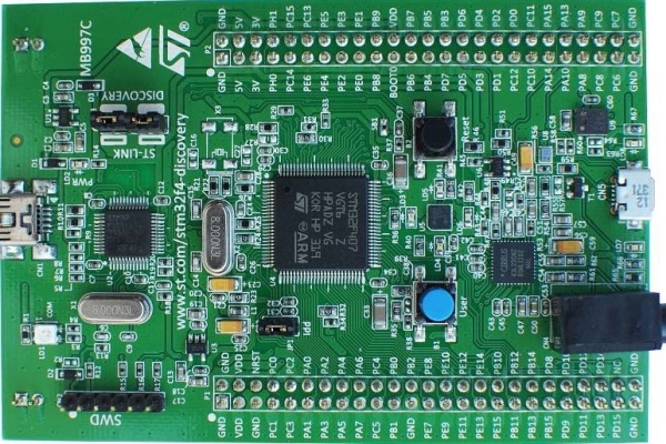
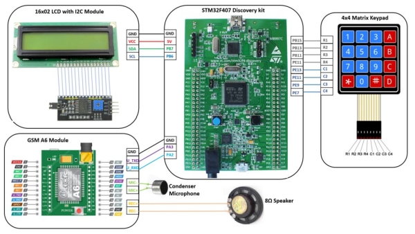

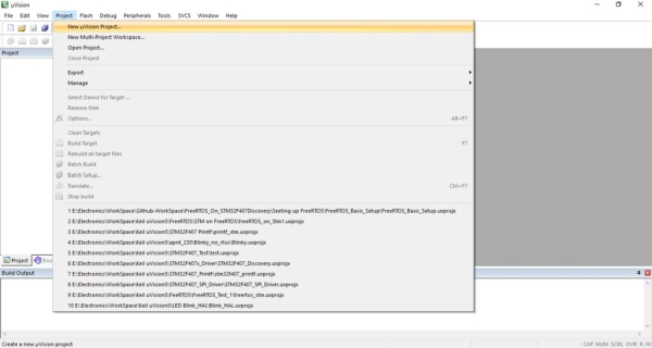
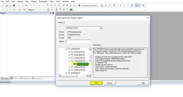
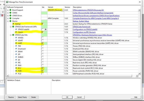
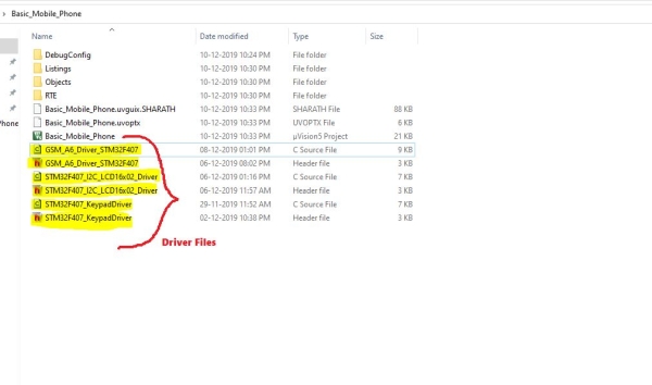
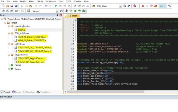


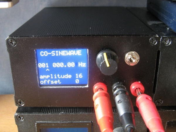
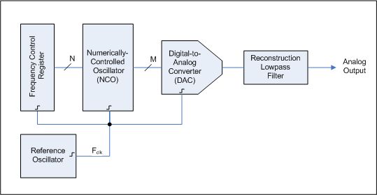
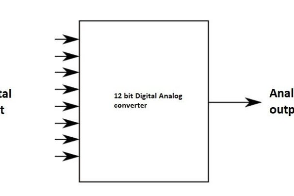
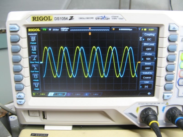
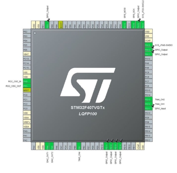
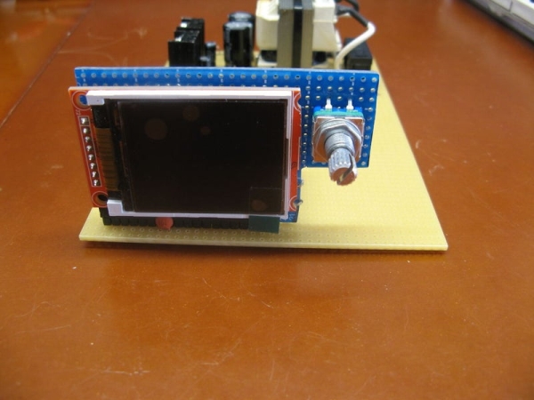


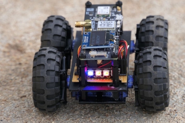
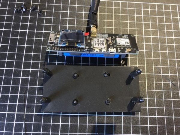
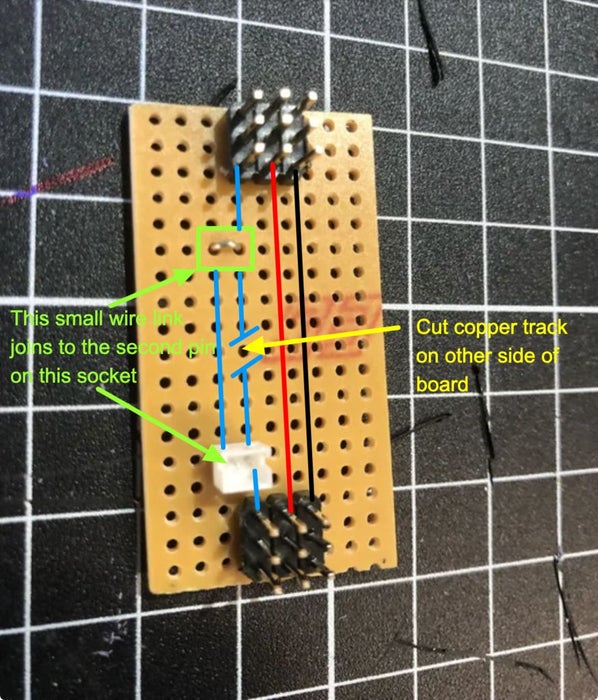
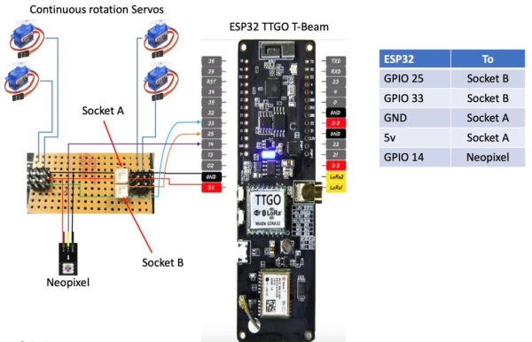
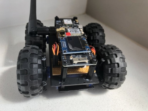
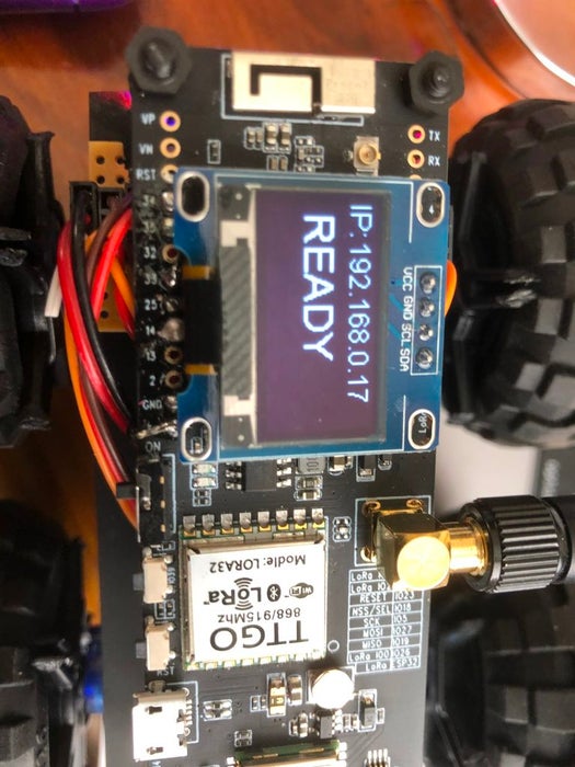


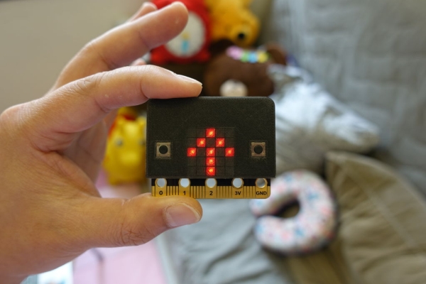
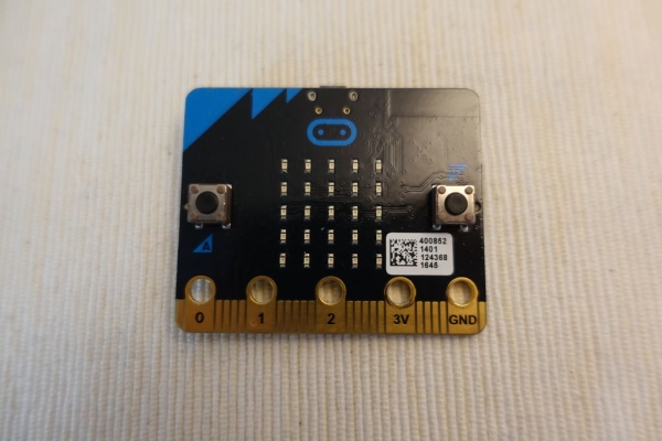
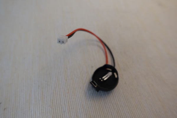
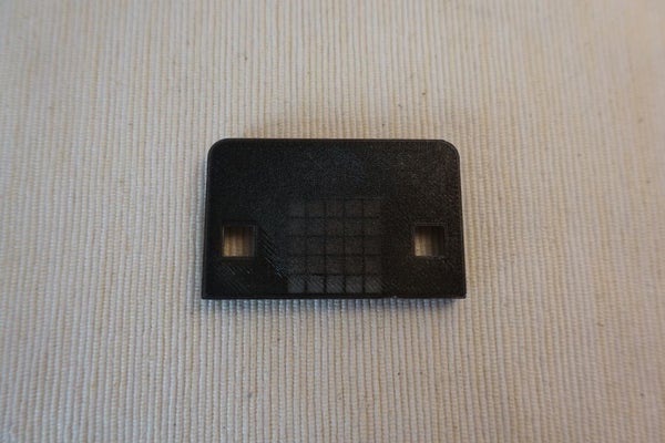
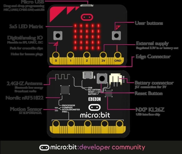
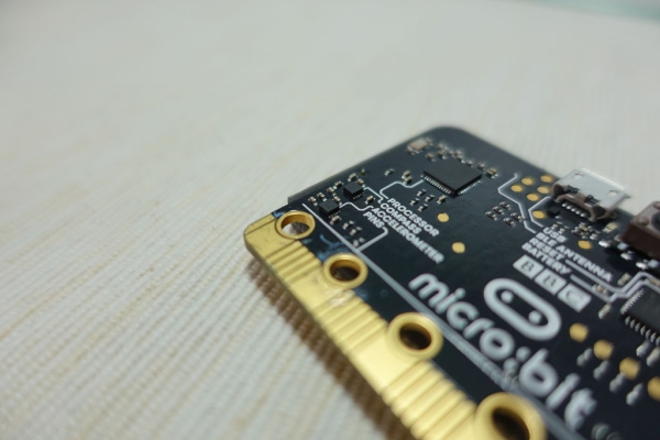
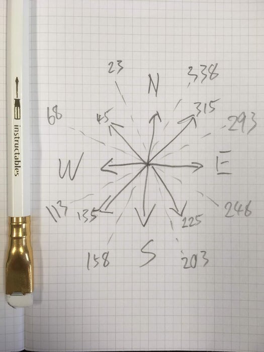
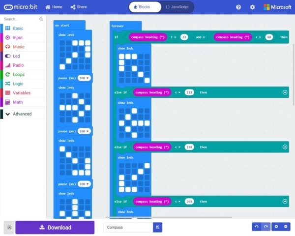
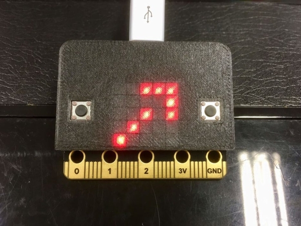
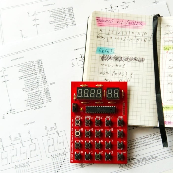
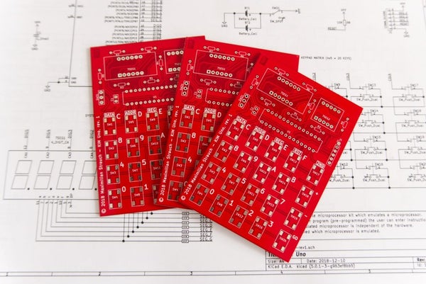
 ), getting it ordered it is the first step. We can then continue with the other steps while the PCB is made and shipped to you.