After you have collected the materials from here.Now connect the Ultrasonic Sensors to the EBot Board{A0-A1} color coded properly. If you have done that, Let’s get on with codin’.
Step 3: Debugging
Now to make sure our Infrared sensors are working perfectly we need to debug it which means to identify and remove errors from (computer hardware or software).
Open up your EBot Blockly app on your computer.
Select Input Readings/Debug.
Select from the drop down list- ‘Infrared Sensor’.
Select the pin in which your first Infrared Sensor is fitted upon. (P.S. you can only check one sensor at a time.)
Click ‘Debug’.
Do the same for the second sensor.
After the downloading is complete and showing values from both the sensors, we can proceed with coding.
(Note: If the debugging encountered with an error, try again, check the connection. If not, then replace the sensor and try again.)
Step 4: Coding
Now you can simply go ahead and copy our code from here or copy the blockly code. Though we recommend the blockly method as shown n the picture as its easier to understand
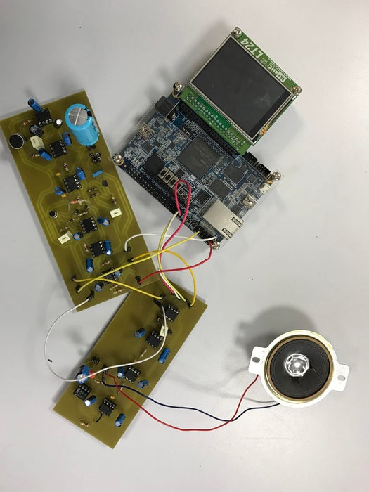
This music synthesizer is quite simple : you just have to blow, sing, or even play music in front of the microphone, and the sound will be modulated and sent through the speaker. Its specctrum will also appear on the LCD display.The Music Synthesizer exists in two versions : you may choose to implement it on a PCB, or if you can’t, a simple Breadboard will do.
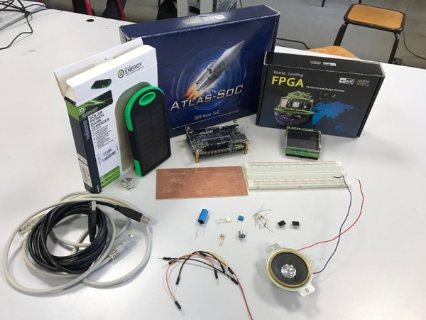
Step 1: Material Needed and Recommendations
To implement this system, you will need the following :
a DE0-Nano-SoC board
a LT24 LCD Display from Terasic
an electret microphone
a basic two-wires (ground and supply) speaker
an Ethernet wire
a PCB or a breadboard
a soldering iron and a PCB engraver, if you decide to implement the synthesizer on a PCB
a battery and its USB connecter (optionnal)
a LM386 power amplifier unit
a MCP4821 Digital/Analog Converter
a LT1054 Switched-Capacitor Voltage Converter
a LM317 Adjustable Reulator
7 TL081 OPAs (DIP-8)
a TL082 OPA (DIP-8)
a 2N5432 transistor
a 1N4148 diode
17 10 µF polarised capacitors
a 1µF capacitor
5 100nF capacitors
a 680nF capacitor
a 100 µF capacitor
a 2.2 µF capacitor
a 1000+µF polarized capacitor (4400 for example)
a 220 µF polarized capacitor
a 0.05 µF capacitor
4 100 Ohms resistors
1 2.2kOhms resistor
1 10kOhms resistor
1 470 Ohms resistor
1 1.8kOhms resitor
1 1MOhm resistor
1 150 Ohm resistor
4 1500 Ohm resistor
Please keep in mind that you may need more components than expected.
We also highly recommend to possess basic knowledge in electronics and SoC design before starting this project.
Step 2: Acquisition Board
Now that you’ve got everything you need, let’s start by making the acquisition board. The microphone collects nearby sounds, then the signal is filtered by a low-pass filter in order to sample it (and thus respect the Shannon theorem) before it is amplified and is finally recorded by the DE0.
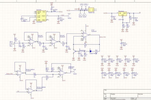
If you are familiar with Altium Design Software and have access to a PCB engraver, you just have to reproduce the schematic shown in the image above, and place the components as we did in the second picture. Otherwise, you may simply recreate this circuit on a breadboard.
In both cases, the values of the resistors, obviously given in Ohms, and the values of the capacitors, given in Farads, are as follows :
R4 : 2.2k
R5 : 10k
R6 and R7 : 100
R3 : 470
R1 and R2 : 18 (these resistors are used to adjust the output voltage that should be 2V so these values may be slightly different for you)
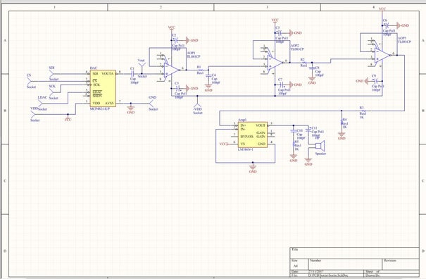
Being able to record sounds is great, but being able to reproduce them is even better! Thus, you’ll need an audio output board, simply consisting of a digital/analog converter, a smoothing filter, a power amplifier and a speaker.
Of course, you can still reproduce the circuit on a PCB (and place the components as shown in the second image) or on a breadboard. In both cases, here are the values for both the capacitors and the resistors :
R1 and R2 : 100
R3 and R4 : wires
R5 : 10
C1 : 1µ
C2, C3, C5, C6, C7, C9 : 100µ (polarized)
C4 and C8 : 100n
C10 : 0.05µ
C11 : 250µ
We’re done with the audio output, so let’s move to the software !
Step 4: Quartus Project
To keep things simple, we decided to start from the “my first-hps-fpga” project provided in the CD-ROM included with the DE0-Nano-SoC. All you have to do is open this project and launch “Platform Designer” or “Qsys” from the tools bar, and reproduce the project above. Then, generate the design and compile with Qsys (see the demonstrations for more details).
Step 5: Enjoy !
Now that the HDL files are generated, you just need to launch the Quartus project. Fort that purpose, plug the USB cable into the USB connector (JTAG) of DE0-Nano-Soc. Then, select Tools > Programming on Quartus. Click on Auto Detect, then select the second option. Afterwards, click the FPGA device (the second one), then “Change file” and select the .sof file previously generated. Finally, click “Program/Configure” check board and click “Start” button to launch the file.
Finally, upload the following C code into the DE0 memory. For that purpose, install Putty on a PC (Linux), link the board to it through an Ethernet connection and by plugging the USB cable into the USB connector (UART) of DE0. Launch and configure Putty with a baud rate of 115200, no parity, one bit stop and no flow control settings. Afterwards, force a fixed IPv4 adress to your PC Ethernet port, enter “root” on Putty shell, then “ifconfig eth0 192.168.XXX.XXX” and “password” followed by a password. Open a shell on your PC, go to the project repository, and enter “scp myfirsthpsfpga root@192.168.XXX.XXX:~/”. Eventually, on the Putty shell, enter “./myfirsthpsfpga”. Enjoy !
BBC micro:bits are great! They are easy to program, they’re packed with features like Bluetooth and an accelerometer and they’re inexpensive.
Wouldn’t it be great to be able to build a robot car that costs next to NOTHING? This project is inspired by the desire for elementary school students to be able to build robots using a minimum of parts and wherever possible, use recycled materials. It takes very little time and encourages students to learn coding, some engineering and to use their craft skills. There’s no cutting or drilling with power tools and no soldering. The primary building materials are a FACIAL TISSUE box (ex. ‘Kleenex’) and a bit of box cardboard. It can be completed in a few days of class time.
You’ll learn some electronics, basic micro:bit coding and how to use the accelerometer and Bluetooth features of micro:bit.
So let’s get started!
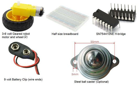
Step 1: Parts List
Parts List
Item Cost Quantity
Tissue box free 1
Box cardboard (corrugated) free 2 pieces that fit in the bottom of the box for stiffening.
Solid core wire minimal Enough for the wiring for the project
BBC micro:bit retail 2 – one for transmitter, one for the car controller
micro:bit GPIO Edge Connector $6 to 15 US 1
Geared Motor /wheel $3 US each 2
Mini breadboard $0.75 US 1
9Volt Battery clip $0.25 US 1
SN754410NE Motor Chip $0.40 US 1
Ping Pong Ball minimal 1
Ball caster (optional) $1.20 US 1 – can use half a ping pong ball or marble instead
Two-sided foam tape $2 at dollar store 1roll – for mounting the motors to the base
White glue You’ve probably already got some
Tools Needed
A ruler
A small utility knife
Hot Glue Gun (optional)
Paper clip or compass for piercing small holes in the tissue box
Rotary cutting tool(optional) or razor saw to cut the ping pong ball in half.
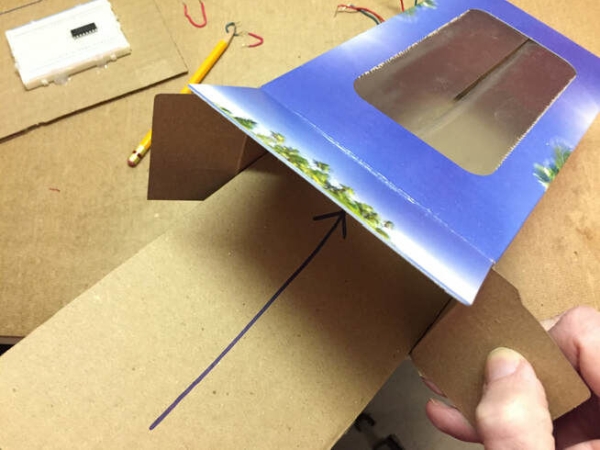
Step 2: Robot Construction
Place the tissue box on the corrugated cardboard sheet so the long side of the box is in line with the ridges of the cardboard. Trace the base of the tissue box on the cardboard. You’ll need two pieces. Carefully cut out the pieces with the knife and ruler. You should trim them so they will fit flat inside the box.Carefully open one end of the tissue box to test fit the cardboard sheets.
Use white glue or carpenter’s glue to glue one piece of the cardboard to the inside base of the box. Put some heavy objects like batteries inside the box to weigh down the cardboard so it will fasten securely to the box. Let it dry.
Before we go further, you may wish to solder short lengths of solid-core wire onto your motor wires and 9 volt battery clip wires. Then cover the joints with heat shrink tubing. It will make it easy to insert these wires into the breadboard. I know I said, “No soldering”, but hey, this IS electronics!
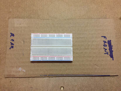
Step 3:
Now start laying out the parts on the other piece of cardboard as shown. Try to mount the breadboard towards the end that will be the rear of the car so the micro:bit and edge connector fit. For consistency, the red-rail of the board is at the top of the pictures. It’s recommended you orient yours the same way for ease of assembly.
Hot glue is great for attaching the breadboard. Then you can easily remove it if you want to use it for another project. DO NOT USE THE TWO SIDED TAPE on the bottom of the breadboard. It holds the metal connections inside the breadboard. If you pull it away, it’ll wreck the breadboard.
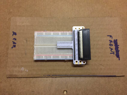
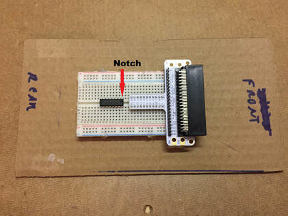
Step 4: Attach the Micro:bit Edge Connector
Now attach the edge connector to the breadboard as shown with the connector pointing to the front of the robot. The pins should straddle the trough(ravine) that runs along the middle of the breadboard.
Step 5: Install the SN754410NE Motor Control Chip
Carefully install the SN754410NE motor chip on the breadboard. The small notch should be pointed towards the edge connector.
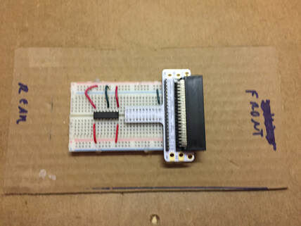
Step 6: Wire the Motor Chip
If you look down on the motor chip from above, with the notch on the right, the pins on top are numbered 1 to 8 from right to left and then the pins on the bottom are numbered from 9 to 16 on the bottom. An explanation of how the motor chip works will be provided at the end of this project.Use small lengths of wire to join,
Pin 1 to the red rail
Pin 8 to the red rail
Pin 9 to the red rail
Pin 16 to the red rail
Use a short length of wire to join the edge connector ground to the blue rail of the breadboard.Use a small length of wire to join the top-side blue rail to pin 4 OR 5 of the motor chip. It’s the chip’s GROUND point and you only need to ground the chip with one wire.
I’m currently building a temperature logger for some guys doing a research in biology. Tried to make it as small as possible, with temperature sensor that can be crammed in small space.
Since the first revision slash prototype of the device was incredibly simple to make and featured easily procured parts, I decided to write up every step of making the device.
The detailed guide with sources and schematics can be found on my blog, I’ll be publishing slightly abridged version here.
Step 1: Gathering Parts
DS18B20 temperature sensor. You can get one in metal package, or a bare IC. I used the latter, because I hope to come up with something smaller than this steel cylinder encasing it.
Blue pill. Inexpensive and versatile board with STM32F103C8T6 as its core.
STLink v2 programmer. You’ll need it to upload your code to STM32 and debug it.
microSD memory card + adapter for it. We’ll convert microSD to SD adapter into microSD to microcontroller one. You can omit this part and just opt for an adapter board for microcontrollers (especially if you don’t want to go further than a prototype) – less soldering, but maybe less fun.
Pushbutton, some jumper wires (these or these), one 4.7k resistor.
Step 2: (Optional) Parts for End Product
The list of parts in the previous step is only good for a prototype. If you want to build something you can give to other people without being scared for the life of your… device, then you’ll additionally need:
Two toggle or rocker switches (both SPST – one to switch operating mode and another as a power switch)
Enclosure-mount connector for temperature sensor. I used XS9K4P: a circular polarized 4-pin connector. Just make sure it can’t be plugged any other than the right way (make it polarized, in other words). This connector is pure awesomeness. It looks like the plug is locked into place after being screwed into receptacle, but it is actually self-locking. You have to pull the outer ‘collar’ part of a plug to unlock it, otherwise it won’t budge.
Coin cell battery. How big depends on what kind of autonomous time you expect to get from this logger, I’m using the beefy-looking CR2477 (25mm diameter, 7mm height, 1Ah on average) to get as much as years. The standard CR2032 (20mm diameter, 3mm height, 220mAh on average) won’t last as long, but it’s encountered more frequently in daily life.
Polarized 3-pin connector to configure temperature logger via UART. I’m going to be using old familiar Molex KK series pin header that everyone knows simply as ‘motherboard fan connector’.
Load switch IC with at least one channel. You’re going to need it to switch off your memory card to conserve power. DS18B20 consumes so little current it can be switched from IO pin. Load switch is not a part that every tinkerer has in their part bin, but luckily I had one that I ordered a long time ago as a sample from Texas Instruments (TSP22960). Well, your time to shine’s finally come, little buddy, after years of laying in a dusty box! You can order one from distributor like Mouser, Farnell, etc..Miscellania like standoffs and tiny screws and 3d-printed enclosure.
I’ll just leave the picture of all the parts I had (excluding the lid of the enclosure with indicator LED and mode switch associated with it) prior to assembling first revision of this device.
Step 3: Prototype
With a device as (relatively) complex as this one, you gotta prototype to make sure all this technology can integrate. Temperature logger will involve FAT filesystem access via SPI, temperature sensor access via OneWire, usage of real-time clock with battery backup.
Got to admit, I never even as much as dabbled in any of those before, at least on STM microcontrollers.
Let’s cobble up something that can read temperature and write it to memory card upon a click of a pushbutton – using only jumper wires! Why solder something as impermanent as this? Prototype code can be found on my blog here.
Step 4: (Optional) Make a Finished Version of Your Device.
Whoo, this prototype building was really educational. Hopefully it taught you something about these little inexpensive Bluepill boards with STM32 microcontrollers, their power saving features and so on. You can stop it here, or you can build a more finished version of this device. To do that, you’ll have to print out the enclosure and solder your device together. For the schematics and finished device’s code, as well as STL models for the enclosure, check out my blog.
Next revision will feature a PCB, serial flash memory instead of microSD and USB configuration instead of Serial.
Thank you for reading this far, and leave your comments and suggestions on this build! Also make sure to post your builds of this simple temperature logger here!
The instructable created by me will help you to build a huge memory capactiy which will come in handy for many projects and measurements. The memory card is suitable for multi-usage and can be way more realaiable in comparison to flash cards and other type of soft memory. The life span of those CMOS EPROM’s is several hundred years.Also one can add additionally an binary 8-bit display just to see the output data on the leds. I have them 2 x 8 led’s on my card.
Step 1: Collecting the Needed Parts to Build the Memory Card…..
Working with electronics prototyping and especially with microcontrollers does require some memory which might be not enough for some tasks involving big programs and data which must be stored…….
In order to build the memory-card, we need EPROM’s. In most cases those EPROM’s are UV-EPROM’s, or EEPROM’s, which stands for electrically earasable/programmable read only memory. In case of UV-EPROM, Ulta-violet based earasable/programmable read only memory. Which means, the EPROM can be programmed once, but then needs an ultraviolet erasable device to clear the memory for further usage. This is not as convinient as the first one, but still quite easy to handle. One can buy such devices in electronics shops. Those EPROM’s are very fast and mostly handle access times of at about 45 ns. Ideally suitable for microcontroller fast read/write cycles. They utilize the parrallel interface which do require some amount of GPIO of the microprocessor. In my case, as one can see from pictures above, I have plenty of those AMD CMOS UV-EPROMs available brand new. So its suits perfect for creating memory card, where several of those IC’s can rest, and thus making ideal solution for bigger memory projects without SPI or other types of memory cards and hassle and complexity which they do bring with them.Beside the CMOS EPROMs, a copper/epoxy based prototyping board is need, size may vary depending on how many of the EPROM’s one plans to embed. The higher the number, the better for capactity. Next thing would be (green) smd leds, and one tht led (red). Low power, low current (c.a. 20mA) should be fine. One needs resistors for each of those led’s (R=150-180 Ohm) for smd leds and (R=470 Ohm) for tht led will do the work. For more convinience I recommend using headers to mae the hole card plugable module, (on solderless breadboards or anywhere else), size of the headers also depend on the amount of embedded IC’s. Jumper wires are needed if you plan to connect them by hand and not on PCB. Each CMOS EPROM require 16 x 10KOhm resistors for address bus data lines and 8x 10 KOhm for data-bus data lines.Each AMD EPROM has 8 ports for data lines and 17 for address lines. So a lot of jumper wires should be available.
Step 2: Assembly Process in Several Steps….
The assembly starts by checking that all the EPROM’s are erased and empty.
>>Step No0.>> Start soldering a power-bus (+/-) 5.0 V for the entire memory card breadboard. This will help to bring the juice to each IC.
>>Step No1.>> Calculating the space for IC’s to be installed, in my case 4 x EPROM’s are embedded, with insertion adapters DIP package. This adapters are soldered to breadboard, not EPROMs, which will help you to replace them in case of failts, and or other maintanance works, without hassle.
>>Step No2. >>Soldering the adapters to breadboard, then checking the power-bus rail and connecting the green smd-led with suitable R=150 Ohm resistor to power rail through the EPROM power-bus. That should be done for each embedded EPROM. The aim is to have power running through led to EPROM, so that one can see visually status of each IC.
>>Step No3. >>On breadboard on lower right corner, a tht red-led with suitable R= 470 Ohm resistor should be soldered. It must be connected directly to breadboard’s power-bus, or barrel connector, to ensure that the memory card is powered-up and running (when led is on system powered).
>>Step No4. >> In this step we need to connect each EPROM’s 17x address-bus data lines to Ground GND with R= 10 KOhm resistors. Pull them down, in case that we are not used by CPU.On the other hand we need the same 17 address-bus data-lines connect to GPIO on CPU, 17 x GPIO dedicated pins, to enable the address read/wite cycles. The 8 bit data-bus data lines are connected to digital pins on CPU (bi-directional) 8 x GPIO. Also one can additionally add 8 x leds with R=470 Ohm just to have a binary display, I find its very helpful for learning and or troublshooting purposes. The 8 data-bus data lines can be shared and interconnected for all EPROMs, In my prototype I did 2×2, with 2 binary displays green, and red, but one can connect all of them to same pins, up to convinience.
Step 3: Control GPIO and Programming ……
Besides the addess-bus data-line, data-bus data-lines and power-bus, each EPROM has control-bus GPIO. Those ones are used for enabling read/write cycles and access to each EPROM, as well as programming them and turning on/off, entering low-power modes etc….. those ports are:
1. PGM-program enable input
2. OE-output enable
3. CE-chip enable
4. Vpp-Program voltage input
Those pins shoud have dedicated GPIO besided all the address/data GPIO. I highly recommend reading the datasheet and having some idea how the EPROM functions before starting to build the memory card. It will help you understand mosty everything with respect to functionality, programming. part No: AM 27C010 1-Megabit, CMOS EPROM/UV-EPROM.
This table will help you to control the functionality, lets say, if we want to write to EPROM which is same as program, we lookup on table what we need to activate: That is CE=LOW, OE=HIGH, PGM=LOW, Vpp=Vpp=12,75 Volt only for programming… particular address line which we want to program should be HIGH, all other address lines = LOW .
Data-bus meanwhile has to be configured as outputs, in order to output the needed data through the 8-bit data-bus. Simple pinMode(), syntax can be used as usual.
In two words: we give Vpp=12,75 program voltage to Vpp pin, then pull down both CE and OE, PGM, after that we put data on CPU data-bus , by pulling the needed address HIGH the EPROM will save the mentioned data at that adrdress. Easy as that. For reading the data from the EPROM, one should refer to that table again, and check what status should those GPIOs be in order to commence other procedures, reading from it, or leting the EPROM go into low power mode. (Standby)
Step 4: Programming the EPROMs
At this point when all the hardware setup is done, and everything is double checked, one can proceed to the next stage.
After going through all the stages above, we can easily start the programming of the memory card, as many times as we want, saving tons of data in each address. Also would be possible to read data from any random address.
There is suitable code (send me pm if code is of interest) together with this device.It very simple one.It will guide maker and help him understand how to program such devices and how everything works. The code configures the suitable GPIO on CPU and then using simple commands runs through every address and writes data there…..if the binary display is connected then, one can see the data output through that leds.It will look like a bar which will start fully lit up and then will gradually decrease when the CPU reads through each address.
Step 5: Summery…..
After all the steps we went through, when the memory-card is ready and powered-on, and the EPROM’s are correctly configured, all the leds on the binary display will lit-up. Also, if we purge the contents of the EPROM’s into serial monitor, it will all be 1, 1111111 meaning that all the led are on. That means EPROMs are empty and factory earsed with all 1’s.
Step 6: Ready to Accept Data…
Now it is possible to program it with the microprocessor, and use the device as external memory module.
At this point you can intergrate it into your projects… and benefit from parallel interface speed combined with speed coming so cheap..
In this tutorial I’m going to tell you about how we can interface keypad with 8051 and displaying keypad numbers in 7 segment display
Step 1: Software Used
As we are showing proteus simulation so FOR CODING AND SIMULATION YOU REQUIRED:
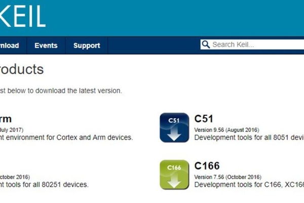
1 Keil uvision: Their are lots of product from keil. so you will be required c51 compiler. You can download that software from here
2 Proteus Software for simulation: This is the software to show simulation. You will get lot of information to download this software.
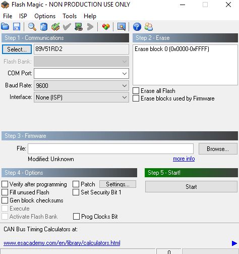
If you are doing it in hardware then you would require one software that is flash magic to upload the code in your hardware. Remember flash magic is developed by nxp. So you can not upload all 8051 family microcontroler through this software. So Philips based controller only you can upload.
Step 2: Components Used:
Here in our demo video we are using proteus simulation but definetly if you are doing it in your hardware you will be required these components for this project:
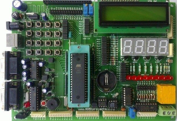
8051 Development board: So if you have this board it will be better so that you can easily upload the code by yourself.
Seven Segment Display: In this project we are using one Common Anode Display.
4*3 Keypad Matrix: Herewe are using 4*3 keypad matrix. So you can use 4*3 matrix or any other matrix like 4*4, no issue. For that a little more step we need to add in our code
USB to UART converter: This is 9 Pin D type male Connector For RS232 O/p Jumper Wires Some Jumper Wires
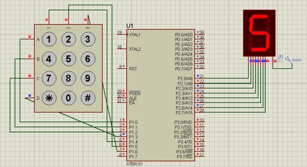
Step 3: Circuit Diagram:
Step 4: Code and Video
The whole Project Description is given in above video
If you have any doubt regarding this project feel free to comment us below. And if you want to learn more about embedded system you can visit our youtube channel
Please visit and like our Facebook Page for frequent updates.
Hello everyone, In this tutorial we are going to tell you about how to count from 0 to 99 using two 7 segment display.
Step 1: Software Used:
As we are showing proteus simulation so FOR CODING AND SIMULATION YOU REQUIRED:
1 Keil uvision: Their are lots of product from keil. so you will be required c51 compiler. You can download that software from here
2 Proteus Software for simulation: This is the software to show simulation. You will get lot of information to download this software.
If you are doing it in hardware then you would require one software that is flash magic to upload the code in your hardware. Remember flash magic is developed by nxp. So you can not upload all 8051 family microcontroler through this software. So Philips based controller only you can upload.
Step 2: Components Used:
Here in our demo video we are using proteus simulation but definetly if you are doing it in your hardware you will be required these components for this project:
8051 Development board: So if you have this board it will be better so that you can easily upload the code by yourself.
Seven Segment Display: There are two types of 7 segment display one is Common Anode and other is Common Cathode. In our Proteus simulation we are using Common Anode Display
USB to UART converter: This is 9Pin D type male Connecter For Rs232 O/p Jumper Wires
As we are using two segments so we have used two 8051 I/O ports for our project. The whole project description are given in the above video.
If you have any doubt regarding this project feel free to comment us below. And if you want to learn more about embedded system you can visit our youtube channel
Please visit and like our Facebook Page for frequent updates.
In this tutorial we are going to tell you about how we can interface lcd with 8051 in 4-bit mode.
Step 1: Software Used:
As we are showing proteus simulation so FOR CODING AND SIMULATION YOU REQUIRED:
1 Keil uvision: Their are lots of product from keil. so you will be required c51 compiler. You can download that software from here
2 Proteus Software for simulation: This is the software to show simulation. You will get lot of information to download this software.
If you are doing it in hardware then you would require one software that is flash magic to upload the code in your hardware. Remember flash magic is developed by nxp. So you can not upload all 8051 family microcontroleer through this software. So Philips based controller only you can upload.
Step 2: Components Required:
Here in our demo video we are using proteus simulation but definetly if you are doing it in your hardware you will be required these components for this project:
8051 Development board: So if you have this board it will be better so that you can easily upload the code by yourself.
LCD 16*2: This is 16*2 lcd . In this lcd we have 16 pins.
USB to UART converter: This is 9Pin D type male Connecter For Rs232 O/p Jumper Wires
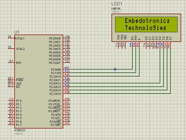
Step 3: Circuit Diagram:
Step 4: Working Principle of This Project:
As in 8 bit we need to connect all 8 data pins of lcd to microcontroller. So total 11 pins of microcntroller we need to use as we have 3 control pins(rs,rw,e) in lcd as well. So the advantage of lcd in 4 bit is that we are saving 4 pins of microcontroller so that we can use these pins for other work.
Now the working principle of code is very simple. First you just download the code.
Ok, Now I will take one function from the code and will tell how that command or data lcd is receiving. In our code first command instruction is
cmd(0x28);
So now it will go to it’s definition
void cmd(unsigned char a) {
unsigned char x;
x=a&0xf0;
cmd1(x);
x=(a<<4)&0xf0;
cmd1(x);
}
so in the above function you can see a is nothing but 0x28. Now through x=a&0xf0, lower nibble will become 0. as we are using AND operator with 0xf0. So in higher nibble only we have data, then through cmd1(x) we are sending 0x20 to port 2 and lcd is connected to higher bits of port 2 so it will receive 2, now immediately we need to send the next nibble which is nothing but 0x8. So for that you can see in the function x=(a<<4)&0xf0, we are shifting a value 4 times and then we are using and operation with 0xf0.
So just understand this
a<<4 is nothing but 0x28<<4, which means 00101000<<4, So we will get
10000000 and we are anding with 0xf0 and we will get 0b10000000 which is 0x80, and from next function cmd1(x) we are sending that data to lcd and now it will receive 0x80 so this way we have sent the whole data 0x28.
So the same way every command and data lcd will receive.
I hope you understand this. Still you can checkout the video which is in the next step. The whole project description is given in that video.
The whole project description is given in the above video.
If you have any doubt regarding this project feel free to comment us below. And if you want to learn more about embedded system you can visit our youtube channel
Please visit and like our Facebook Page for frequent updates.
This channel just now we have started but daily you will get some videos regarding embedded system and IoT.
This is a very basic project of 8051. In this project we are going to tell you about how we can interface 16*2 lcd to 8051 microcontroller. So here we are using full 8 bit mode. In the next tutorial we will tell about 4 bit mode as well.
Step 1: Software Used:
As we are showing proteus simulation so FOR CODING AND SIMULATION YOU REQUIRED:
1 Keil uvision: Their are lots of product from keil. so you will be required c51 compiler. You can download that software from here
2 Proteus Software for simulation: This is the software to show simulation. You will get lot of information to download this software.
If you are doing it in hardware then you would require one software that is flash magic to upload the code in your hardware. Remember flash magic is developed by nxp. So you can not upload all 8051 family microcontroleer through this software. So Philips based controller only you can upload.
Step 2: Components Required:
Here in our demo video we are using proteus simulation but definetly if you are doing it in your hardware you will be required these components for this project:
8051 Development board: So if you have this board it will be better so that you can easily upload the code by yourself.
LCD 16*2: This is 16*2 lcd . In this lcd we have 16 pins.
USB to UART converter: This is 9Pin D type male Connecter For Rs232 O/p
Sonoff is a device line for Smart Home developed by ITEAD. One of the most flexible and inexpensive devices from that line are Sonoff Basic. It is a Wi-Fi enabled switch based on a great chip, ESP8266. This article describes how to set up the Cloud4RPi service on a Sonoff Basic smart switch.
In the previous instructable, we explained how to flash the new MicroPythonfirmware on the Sonoff Basic or Sonoff Dual smart switch. In this article, we are going to restore a part of the original Sonoff-enabled functions using Cloud4RPi.
Step 1: Connecting Via WebREPL
Earlier we accessed the Python REPL interface via the UART protocol. Since the ESP8266 is a Wi-Fi module, we can communicate with it wirelessly. Turn your MicroPython-enabled board on, access its command line and enter the following command to enable the WebREPL:
>>> import webrepl_setup
This command starts the configuration wizard where you can configure the WebREPL auto-start, set the password, and reboot once finished.
After rebooting, connect to your Wi-Fi network by executing the following commands (replace the Wi-Fi configuration with your data):
>>> from network import WLAN
>>> STA = WLAN(0); STA.active(1)
>>> STA.connect('__YOUR_WIFI_NETWORK_NAME__', '__PASSWORD__')
>>> STA.ifconfig()
Wait a few seconds and check the STA.isconnected() output. If it outputs False, double-check the Wi-Fi credentials, reconnect, and check that the STA.isconnected() outputs True. To get the ESP8266’s IP address in your network, execute the following command.
>>> STA.ifconfig()[0]
'192.168.1.108'
You can now connect to the ESP8266 via the WebREPL (download this HTML document and open it with your browser).
At the right-hand side of the WebREPL interface, you can see the file-manager fields allowing you to upload and download source code files to the ESP8266’s virtual file system.
Step 2: Connecting to Cloud4RPi
Download the required files to your computer:
simple.py: The MQTT Library for MicroPython. Save this file as mqtt.py when downloading.
cloud4rpi.py: The Cloud4RPi client library for MicroPython.
Open the main.py file in a text editor (for instance, Visual Studio Code) and replace the following strings:
__SSID__ with your Wi-Fi network name.
__PWD__ with your Wi-Fi network password. If you have an open network, remove the ‘__PWD__’ element without removing the trailing comma so that the WIFI_SSID_PASSWORD variable becomes a tuple with one element.
__YOUR_DEVICE_TOKEN__ with the token displayed at the top of the device page on cloud4rpi.io. If you do not have a token, open the Devices page, create a device using the New Device button in the top right corner, and use its token.
Change the LED_PIN to 13 and the BUTTON_PIN to 0.
Save the file main.py and upload the mqtt.py, cloud4rpi.py and main.py files to your ESP8266 via the WebREPL’s right-hand side panel.
Reset the ESP8266. You can use the console for this:
>>> import machine
>>> machine.reset()
The file named main.py is started automatically on boot.
If everything goes well, you can see the device is on the Cloud4RPi device page.
Step 3: Setting Up Control Panel
Go to the Control Panels page and add a new control panel and add the Switch widget and bind it to the LED variable.
Use the LED switch on the control panel to turn the Sonoff LED on.
Add a Text widget and bind it to the Button variable. Configure different colors for the “true” and “false” strings. You can now press the hardware button and see how the widget changes.
You can control the Sonoff Basic relays by adding a new variable bound to the hardware pin 12.
Lets describe a clock… “Clock is a device that counts and shows time(relative)”!!!
Guess I said it right so lets make a CLOCK with ALARM feature.
NOTE: it will take 2-3 minutes in reading please read the whole project or else I will not be responsible for any part damage.
Step 1: COMPONENTS REQUIRED
6 components needed :
1. Microcontroller (I have used AT89S52-8051 family), any programmable microcontroller can be used.
2.7 segment display
3.Crystal oscillator (12MHz)
4.Capacitor (10uF, 33pF/22pF)
5.LEDs
6.resistances (330 Ohm)
7.buzzer (piezo)
8.push switches
And I’m not including soldering iron, wire, flux….. electricity !!! help me out
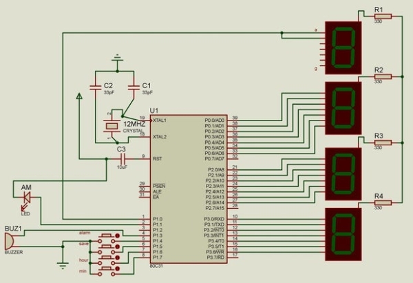
Step 2: Circuit Diagram
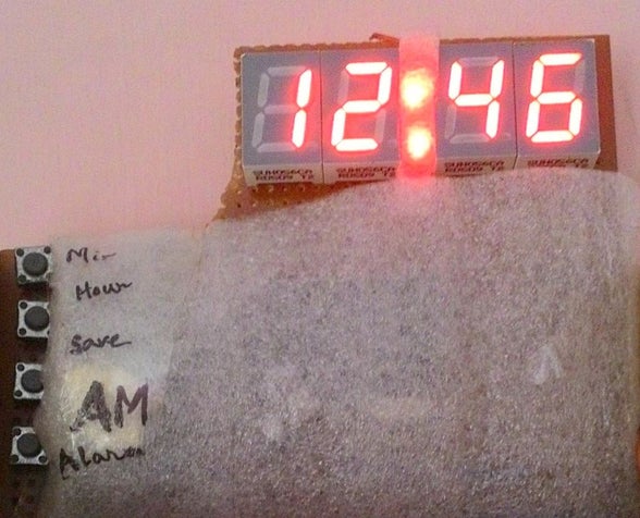
This is the circuit diagram of the digital clock using 8051 microcontroller.
As we can see the microcontroller is connected to three 7 segment display with distinct ports not multiplexed and the last hour digit is only connected to a pin as it only shows 1.
LED and buzzer are self explanatory according to the code.
1 of the LED is for AM and I have connected another LED not shown in the figure for alarm.
Crystal Oscillator of 12MHz is connected to clock speed and attaining the exact 1second counting using the interrupt property of the microcontroller.
THE MIDDLE LEDS DENOTING SECOND ARE CONNECTED TO “28TH AND 32ND” PIN.
Please pardon me, 3 LEDs aren’t shown in the circuit diagram for my laziness.
28th pin LED: first 30 second blink
32nd pin LED: rest 30 second blink
****contributing to a whole minute!!*** i’m sure after this project I came to know 60 second makes a minute!!! WOW
Step 3: Coding
I have used keil software to built a C code for the RTC using microcontroller and getting hex file.
The fundamental thing in the coding part is, when the pin of each port will toggle for showing the digit related to each 7segment display.
The interrupt property of 8051 is used to count and reload per second. for example only, Just like creating a delay function with argument 1 causing 1second delay. (TMOD,TL0,TH0,IE every value contributes to the time making)
The LED for AM is programmed for alternate 12 hour.
As well as alarm can also be set for AM or PM specifically and the buzzer pin is passed with frequency code to buzz on the alarm time. Alarm button with min, hour & save switch is used for setting alarm. On twice clicking alarm disables alarm feature.
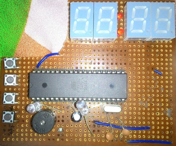
Step 4: Finally…
ALL done !!! Now iT’S time to enjoy the clock that’s bright and exact.
NO DISCREPANCIES WITH REAL TIME…
IF you liked it “make it” and “make it your favorite”…
Sonoff is a device line for Smart Home developed by ITEAD. One of the most flexible and inexpensive devices from that line are Sonoff Basic and Sonoff Dual. These are Wi-Fi enabled switches based on a great chip, ESP8266. While the Sonoff infrastructure may work quite well for basic users, others may want to hack into that hardware and run their own code on it. The hardware of Sonoff Smart Switches is amazing, considering its low price:
ESP8266 with 1MB flash
220V AC integrated power adapter
10A Relay (or two in Sonoff Dual)
Onboard LED (or two in Sonoff Dual)
Onboard Button
If you want to take a full control over this hardware using your favorite programming language, this tutorial is for you.
Step 1: Hacking the Hardware
ESP8266 is programmed via the serial port. Both Sonoff Basic and Sonoff Dual have it on the PCD.
You may need to solder a pin header on the PCB to easily connect a USB-UART adapter.
Step 2: Preparing to Hacking the Software
I love Python, so I’m going to use the MicroPython firmware. You can also use any supported SDK. Let’s proceed to flashing MicroPython instead of the proprietary Sonoff firmware:
Install the esptool python package that makes flashing the ESP8266 easier:
pip install esptool
Download the latest stable MicroPython firmware from the MicroPython downloads page. Connect a USB-UART adapter to the board. For safety, it’s recommended to power the board from the adapter instead of the 220V AC socket. Note that you may only use 3.3V, if you connect the ESP8266 chip to a 5V power source, it will die.
Boot ESP8266 into the Flash Mode. You can do it by pulling down the GPIO0 pin while powering the device on:
On Sonoff Basic, the GPIO0 is simply the button. Connect the USB-UART adapter to your PC while holding the button and you are in the Flash Mode.
On Sonoff Dual, things are a bit harder. You need to short circuit two pads on the PCB while powering the board. The required pads are shown on the picture above. Use tweezers or solder a small wire between them.
When the ESP8266 is in the Flash Mode, the board’s LED should not flash.
Make sure that you can access the serial port opened by the the USB-UART adapter. On Linux it’s probably \dev\ttyUSB0, on Mac you should search for something like “usbserial” or “usbmodem” in the ls \dev\cu.* or ls \dev\tty.* command output, on Windows it should be COM3 or higher. Install the USB-UART adapter drivers if necessary.
Erase the flash using the esptool. Replace the /dev/ttyUSB0 for your port if required:
esptool.py --port /dev/ttyUSB0 erase_flash
You may need to run esptool.py as a superuser to access the serial port.
Step 3: Flashing
If the erasure was successful, cut the board’s power, boot the ESP8266 in the Flash Mode again, and flash your firmware:
If the flashing was successful, cut the board’s power, connect it again without pressing the button, and open the serial port in a terminal. On Linux and Mac you can use screen /dev/ttyUSB0 115200 (replace the /dev/ttyUSB0 for your port if required), on Windows you can use PuTTY (the default baud rate is 115200). Once you connect, press Enter, and if you see three angle brackets of Python shell, than everything works!
>>>
>>> help()

Welcome to MicroPython!

For online docs please visit http://docs.micropython.org/en/latest/esp8266/  .

For diagnostic information to include in bug reports execute 'import port_diag'.

Basic WiFi configuration:

import network
sta_if = network.WLAN(network.STA_IF);
sta_if.active(True)
sta_if.scan() # Scan for available access points
sta_if.connect("<AP_name>", "<password>") # Connect to an AP
sta_if.isconnected() # Check for successful connection
# Change name/password of ESP8266's AP:
ap_if = network.WLAN(network.AP_IF)
ap_if.config(essid="<AP_NAME>", authmode=network.AUTH_WPA_WPA2_PSK, password="<password>")

Control commands:
CTRL-A -- on a blank line, enter raw REPL mode
CTRL-B -- on a blank line, enter normal REPL mode
CTRL-C -- interrupt a running program
CTRL-D -- on a blank line, do a soft reset of the board
CTRL-E -- on a blank line, enter paste mode

For further help on a specific object, type help(obj)
>>>
In the next instructable, we will describe how to interact with the Cloud4RPi platform via an MQTT protocol.
This project uses green surface-mount LED’s along with an AVR ATTiny45 microcontroller to simulate the behavior of fireflies in a jar.
(note: the firefly behavior in this video has been greatly sped up in order to be easier to represent in a short film. The default behavior has significantly more variance in its brightness and delay between plays.)
Step 1: About This Project
The inspiration for this project comes from having never lived in an area where fireflies were common and being deeply fascinated whenever I encounter them in my travels.
The flash patterns have been digitized from firefly behavioral research data found online and were modeled in Mathematica so that variations of speed and intensity could be generated. The final output was transformed by a lightness function and written into header files as 8-bit PWM data.
The software is written in avr-gcc C and source code is provided along with a pre-compiled .hex for convenience. The code has been significantly optimized for efficiency and to minimize power consumption. Crude runtime estimates predict a 600mAh 3V CR2450 battery should last between 4 to 10 months, depending on the song pattern used. RIght now the source comes with two patterns, song1 and song2, with song2 as default. Song2’s estimated runtime is 2 months, song1’s is 5 months.
This project involves a fair amount of surface-mount level soldering. However the circuit design is trivial and the fact that we’re able to use an off-the-shelf SMD prototyping board rather than having a custom PCB made greatly saves on cost. It would be very simple to create a non-surface mount version using the PDIP version of the ATTiny45 and through-hole LED’s.
The cost of the electronic components comes in at around $10-$15 (after shipping) or so and assembly time is on the order of 2 hours.
Step 2: Parts
In this section I list the parts I used in the construction of this project. In many cases, the exact part is not required and a substitute will suffice. For instance, it isn’t required that you use a CR2450 battery to power the circuit, any 3V power supply will suffice and CR2450’s just happened to be the cheapest battery that I found which fit the size and capacity requirements I was looking for.
– 1 AVR ATTiny45V microcontroller, 8-pin SOIC package (DigiKey part# ATTINY45V-10SU-ND) (see note 1) – 1 Surfboard 9081 SMD prototyping board (DigiKey part# 9081CA-ND) – 6 Green LED’s (DigiKey Part# 160-1446-1-ND) (see note 2) – 1 22.0K Ohm 1206 resistor (see note 3) – 2 100 Ohm 1206 resistors (see note 2) – 1 CR2450 battery holder (DigiKey Part# BH2430T-C-ND) – 1 CR2450 battery (any 3V power supply will do) – 1 spool of #38 Magnet wire (Ngineering.com Part# N5038) – 6 inches or so of bare thin wire, I used stripped wirewrapping wire but about anything will do
Notes:
#1 – The difference between an ATTiny45V and an ATTiny45 is that the ATTiny45V is spec’d to run on voltages between 1.8V – 5.5V while the ATTiny45 wants 2.7V – 5.5V. For this project, the only implication is that the ATTiny45V can possibly run for just a little bit longer as the battery dies. In reality this probably isn’t the case and the ATTiny45 can be considered interchangable with the ATTiny45V (guess which one I happened to have on-hand when I started?). Use whatever one you can get your hands on. Also, the ATTiny85 will work just fine too for a little bit more money.
#2 – Substituting a different model of LED with different current-draw characteristics will have implications on what resistor you use. See the Circuit Schematic section for more information and check the spec sheet for your LED’s.
#3 – This is only a pull-up resistor, the specific value is not important. It just needs to be ‘big enough’ without being ‘too big’. See the Circuit Schematic section for more information.
Step 3: Tools
These are the tools I used:
Radio Shack #270-373 1-1/8″ Micro Smooth Clips “clip-on-a-stick” – One of the Micro Smooth Clips mounted on a nail or other sort of stick. Temperature-Regulated Soldering Iron with a fine tip (I use the Weller WD1001 digital soldering station with 65 watt iron and 0.010″ x 0.291″L micro tip). On a budget however, a 15-watt Radio Shack style soldering iron should be fine. Helping Hands Multimeter (for circuit testing) Wire shears Flux (I like the Kester Water-Soluble Flux-Pen, available at HMC Electronics (part# 2331ZXFP)) Solder (the thinner the better) Tweezers Exacto Knife / Razor blade
Step 4: Circuit Board Assembly – Part 1 of 3
Preparing the circuitboard and attaching the resistors –
Flux the pads –
I tend to flux everything, even when using solder that already contains flux. This is especially true when I’m using the water-soluable flux-pen since cleanup is so easy and the pen makes it easy to not get flux everywhere.
Solder jumper wire across pads as illustrated –
The consequence of not having our own PCB made for this project is that we have to add our own bus wires. Also note the bus wires on PIN_C, PIN_D, and PIN_E. These are not strictly necessary but it looks cleaner this way and also gives us some elbowroom when attaching a clip to the microprocessor for programming.
Solder resistors to the board –
There are a number of good guides on the internet with examples of how to solder surface mount components. In general, you want to start by puting a little bit of solder on one pad. Holding the component in a pair of tweezers, heat the solder and hold one side of the component in the solder until it flows onto the pin. You want to keep the component flush with the board while you’re doing this. Then, solder the other side. See the pic.
Step 5: Circuit Board Assembly – Part 2 of 3
Soldering the microcontroller to the board –
Bend pins on the microcontroller –
Another consequence of not having our own PCB made is that we have to deal with the unusual width of the ATTiny45 chip which happens to be slightly wider than will comfortably fit on the Surfboard. The simple solution is to bend the pins inwards so that the chip stands on the pads instead of sitting on them.
Solder microcontroller to board –
Again, there are many SMD soldering guides out there but the executive summary is this:
– Flux the pins of the chip (I find this makes it *much* easier to get a good solder joint, especially with the weird surface topology of these bent pins) – Hold the chip to the pad and draw solder down from the square pad and onto the first pin of the chip (add more solder if there isn’t enough on the square pad but you’ll typically have enough already). – Make sure that the solder actually flows up and *onto* the pin. The soldering motion is sort of like “pushing” the solder onto the pin. – Once the first pin is soldered, go to the pin on the opposite corner of the chip and solder that down as well. Once those two corners are tacked down, the chip should remain firmly in place and the remaining pins become simple to complete.
Also, be very careful that you solder the chip to the board in the correct orientation! If you look closely on the chip you’ll see a little round indentation on the top in one of the corners. That indentation marks pin #1 which I’ve otherwise marked as the “reset’ pin on the chip (see diagram). If you solder it down in the wrong orientation, I promise you that it won’t work
Step 6: Circuit Board Assembly – Part 3 of 3
Test all connections –
Since everything is fairly small here, it’s quite easy to make a bad solder joint that looks fine to the eye. That’s why it’s important to test everything. Use a multimeter and test all of the pathways on the board for connectivity. Make sure to test everything, for instance don’t touch the probe to the pad that the pin of the chip looks soldered onto, touch the pin itself. Also test the resistance values of your resistors and make sure they match with their expected values.
A small problem now is easy to correct but becomes a big headache if discovered after all the LED strings have been attached.
Step 7: Making a Firefly LED String – Part 1 of 4
Prepare the wires –
Ngineering.com has a good writeup of how to work with this magnet wire and covers tinning as well as twisting it which are two steps of making a firefly LED string. However I’ve never been satisfied with the results of burning away the insulation as they describe in the guide and have instead settled on gently scraping the insulation away with a razor. It’s quite possible that I simply wasn’t doing the tinning steps right (despite many attempts) and your own mileage may vary.
Cut red and green wires to desired length of string. I prefer to use different lengths of wire for each firefly string so that once assembled they don’t all hang at the same “altitude”. Generally I calculated the lengths that I was going to use by figuring out the shortest string (based on measuring the jar I was going to use), the longest string, and dividing the interval between them equally into 6 measurements. The values I ended up with for a standard widemouth jelly jar are: 2 5/8″, 3″, 3 3/8″, 3 3/4″, 4 1/8″, 4 5/8″.
Strip one end of each wire exposing a millimeter or less. Using the razor method, gently scrape the insulation away by softly dragging the blade over the wire. Turn the wire and repeat until the insultation has been removed. Using this method I find it hard to only strip a millimeter of wire so I simply cut off the excess.
Step 8: Making a Firefly LED String – Part 2 of 4
Preparing the LED –
Using a microclip, pick up an LED so that the bottom side is facing out, exposing the pads.
Mount microclip + LED in the helping-hands and apply flux to the pads on the LED.
Step 9: Making a Firefly LED String – Part 3 of 4
Soldering the LED –
Using another microclip, pick up the green wire first and mount it in the helping-hands.
Now comes the hardest part of the project, soldering the LED. Manipulate the helping hands so that the exposed part of the green wire is resting gently on the cathode pad of the LED. This is the time-consuming part that requires patience and cannot be rushed. Plan your moves in advance and act slowly and with deliberation. This is basically ship-in-a-bottle type delicate work and shouldn’t be underestimated. However you don’t have to be the favorite son of a watchmaker in order to pull this off either, it *is* within the realm of mortals. I find it considerably easier to manipulate the arms of the helping hands rather than the wire itself or the microclip.
Rest the exposed part of the wire on the cathode pad and arrange your mangifying gear and lighting to make sure you can perfectly see what you’re doing in preperation for soldering.
Using a soldering iron set to around 260 degrees C, pick up a very small blob of molten solder onto the tip of the iron and, very gently, touch the tip of the iron to the cathode pad on the LED. A small amount of solder should instantly run off of the tip and onto the pad (thanks to the flux), securing the wire to the pad in the process. Be careful not to burn the LED by holding the iron to the pad too long (3 seconds max, when done right you need less than 0.10 seconds of tip contact, it’s very fast).
Unfortunately what tends to happen here is that you knock the wire off the pad with the tip of the iron, forcing you to go through setting it all up again. For that reason you have to be *very* slow and gentle with the iron. I tend to place my elbows on the workbench on either side of the helping-hands and hold the iron with both hands in a seppuku type grip, gently bringing the iron down towards the pad. This grip is sometimes the only way I can get enough control. Another tip: don’t drink a pot of coffee before attempting this.
This does get easier with practice.
(Very gently) tug on the green wire to test that it’s firmly secured. Release the wire from the microclip and, without changing the orientation of the LED, repeat the process with the red wire, only this time soldering it to the anode pad of the LED. Since the red wire will be flying over the cathode (green) pad, it’s important to not have too much exposed red wire, lest it come down in contact with the cathode pad and create a short.
Work is of two kinds: first, altering the position of matter at or near the earth’s surface relatively to other such matter; second, telling other people to do so. The first kind is unpleasant and ill paid; the second is pleasant and highly paid.
Bertrand Russell
The joy of measuring work or in this case power that comes from biking. Units that parse the tiniest efforts in specialized crank arms and bottom brackets are pretty expensive. There was recently even a new variety that somehow used algorithms related to your rear tire pressure to measure…something: http://www.velonews.com/2017/09/bikes-and-tech/aro… Now that Load Cells and their attendant amplifiers have become very cheap and the software is really easy to use I have adapted a couple of these for use in a modified bike pedal. When you are done with your ride the WEMOS D1 inside the pedal publishes its data to a couple charts on https://thingspeak.com using MQTT. A wireless Qi charger for the unit makes it easy to maintain.
Step 1: Gather Your Materials
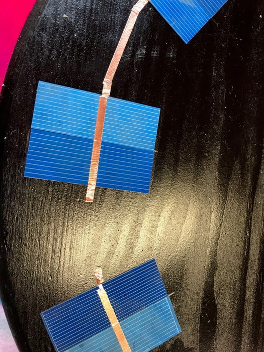
1.The heart of the unit is the micro load cells–I used the ones from:
They come with included amp and are really cheap–about $6.
A pair of them worked well connected in parallel–and even though the weight limit seemed iffy it worked for all my rides. If you want to go for the 50kg limit you will find it below:
Give or take the total cost for these parts is about $30.
Step 2: Build the Mechanicals
The load cells are really easy to use. Sparkfun has a great introduction to load cells and the HX711 amplifier that you need to make them work: https://learn.sparkfun.com/tutorials/getting-star… The setup and the software that you need to download and calibrate them are all on their website. Load cells have to be cantilevered out with a stable platform on one end and the load you are measuring on the other. In the design I used a metal cutting wheel to get rid of the upper deck on the pedal. It is aluminum and easily done. Each pedal is slightly different but you want to develop a stable platform to mount the load cells with bolts. They are tapped for 5mm on the stable end and 4 mm on the load end. You will have to drill mounting holes in the lower deck to accommodate these holes. The upper deck is made out of aluminum diamond plate from the big box store. I placed a crosspiece of heavier aluminum bar to share the load over the ends of the load cells and mounted the diamond plate over this.
Step 3: Sensors and Such….
The hall sensor is enclosed in epoxy within an aluminum housing for stability. The sensor included an LED within it that made testing it much easier. The Neopixels were epoxied to the upper deck cover under holes drilled to the size of the round LED turrets. The Qi charger was epoxied to the lower deck cover on the outside. It has to be in close proximity to the charger unit and cannot be mounted under the aluminum shell. The unit itself seems to resist the torture that occasionally results from stepping on this side of the pedal. The output of the Qi charger is a microUSB connector that is led in to the charger unit (TP4056) through an opening that is sealed with epoxy.
Step 4: Electronics
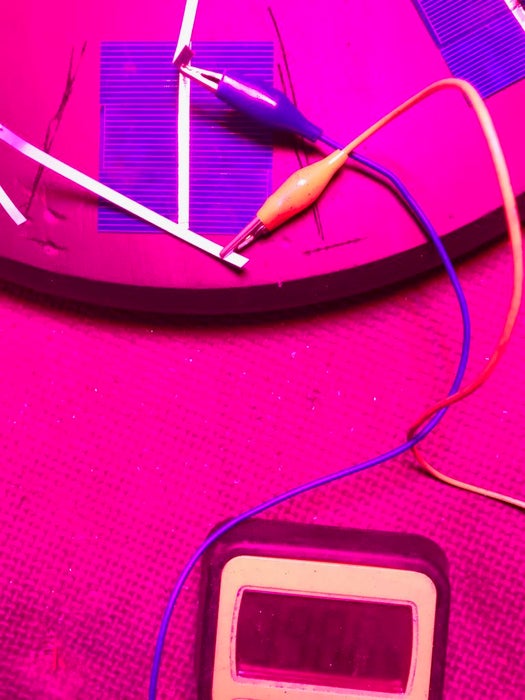
The fritzing diagram will show you the layout of all the electronic components. Get started by wiring up the load cells in parallel. Four wires come out of the strain gauges that are inside the aluminum bars. They are color coded and you connect like colors together and then attach them to the HX711 amplifier as described in the Sparkfun tutorial. The software will then lead you through getting a calibration factor for your load cells and then using the example program to test and make sure that your setup is weighing things correctly. I temporarily attached a oled output so I could carefully monitor the setup–and even tried it on my bike. Unfortunately you can’t read the output well in the light which resulted in using the LEDs for color calibrated output instead. The components are mounted on a perf board and the on/off switch is connected between the charger and the booster. The battery and the charger unit and booster are located on one side of the pedal and the WEMOS and amp are located in the other.
Step 5: Software
The software uses one function to obtain the maximum weight applied to the pedal within a 5 second measurement window and then another function to figure the cadence for the next 5 second window. I looked through a variety of sources for figuring the power associated with each stroke and you can get pretty “granular” with this material. The weight on the pedal will be vary with each stroke from some maximum to a minimum with the other pedal stroke. It will have a myriad of inaccuracies associated with this including measuring force in the down direction only. So compromising I designed the software to look for the highest kg weight for a set period and figured it would compensate for a variety of errors. If you want you can have the system sample constantly, find the average wt and then double it for both pedals. The cadence is measured in a separate timed function so the two samples with not interfere with each other. The calculation for power is force, distance moved and cadence. P[W] = F[N] * l[mm] * w[rpm] * 2 * pi / 60,000
The software has a running average for both weight and power that stops when the bike stops. About once a minute it dumps the averages into two arrays with a capacity for 100 integers each to record your history. The light output from the 3 LEDs varies with power output and runs from a cool blue to a hot red if you get into Lance territory. At the end of your ride you set the pedal so that the Hall sensor is constantly on and after about 30 seconds it will begin the upload sequence for the thingspeak web page. So make sure your back at home within wifi range when you do that or you can set up your phone for a wifi hub if you are on the road. You have to change the code for the name of your network and your wifi password. The information for uploading MQTT on the thingspeak is located here and I just followed their example carefully: https://www.mathworks.com/help/thingspeak/use-ard…
You will have to set up a channel and set up the graphs that you want to populate. You get your api key as well as the channel number to allow you to upload to the correct spot. The minimum time between uploads is 20 seconds so it will take about 1/2 hour to upload an 90 minute ride. You can also add cadence to the upload or anything else that you want recorded. The Qi charger straps on to the the pedal to recharge while you’re downloading. The software goes into wifi sleep when its done.
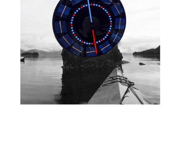
Step 6: Using It
I have been using the pedal power meter on my fat tire bike–you can see in the photo its the only thing not covered in mud. (Notice the bear spray in the water bottle cage–Alaska biking has its own unique risks…) To activate the hall sensor just use a standard magnet that comes with a bike computer and stick it onto the crank arm where it will activate the sensor with each pedal rotation. I used a web based calculator that estimates your power output on a hill climb given your weight, height of your climb and time and found the result was within spitting distance of what the meter was reading. http://www.u.arizona.edu/~sandiway/bike/climb.htm…
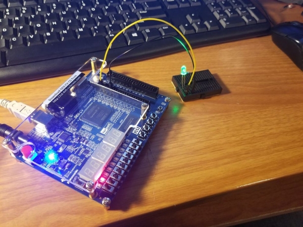
This tutorial will show you how to turn on an LED using both the built-in LED on a development board as well as using a GPIO pin. I happen to be using a DE0 CV Dev board from Terasic. We will be using the Quartus design environment to do this.
– USB blaster drivers (they should be included in the Quartus download)
Hardware Requirements
– FPGA Dev Kit
– LED with resistor (330ohm- 1kohm should be fine)
Step 1: Project Setup (1)
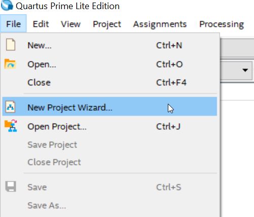
Create a new project in Quartus
Step 2: Project Setup (2)
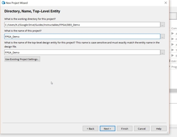
Set your save locations
Step 3: Project Setup (3)
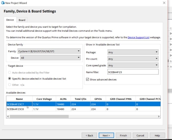
– Select empty project type
– Click next on the add files screen
– Select your chip
Step 4: Project Setup (4)
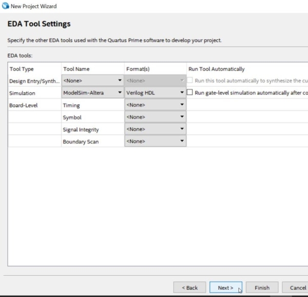
-Select your tools
– Click finish
Step 5: Project Setup (5)
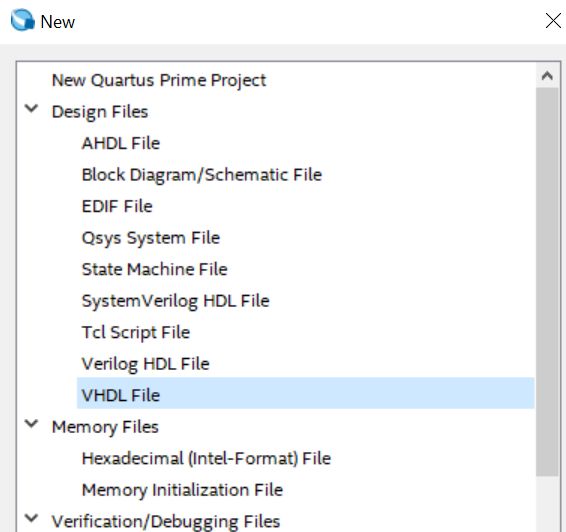
– Create new vhdl file
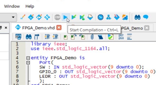
– Copy the code below into it
–START
library ieee; use ieee.std_logic_1164.all;
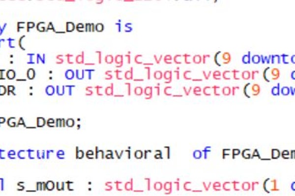
entity FPGA_Demo is
Port(
SW : IN std_logic_vector(9 downto 0);
GPIO_0 : OUT std_logic_vector(9 downto 0);
LEDR : OUT std_logic_vector(9 downto 0)
);
end FPGA_Demo;
architecture behavioral of FPGA_Demo is
signal s_mOut : std_logic_vector(1 downto 0);
begin
process(SW)
begin
s_mOut <= SW(9 downto 8);
end process;
GPIO_0(0) <= s_mOut(1);
LEDR(8) <= s_mOut(0);
end behavioral;
–END
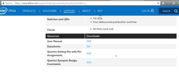
Step 6: Add Your Board’s .qsf
– The QSF file sets the pin assignments for your board.
– using this link you may be able to find the .qsf file for your dev kit…download it.
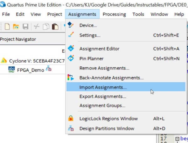
Step 7: Import Pin Assignments
Import the pi n assignments and select the .qsf file you just downloaded
Step 8: Configure Your Pins
I happen to have a board with 10 LED and switches as well as 2 2×20 GPIO headers. Your board may be different. You may need to check some of the PORT settings in the .vhdl file and make sure they will work with your board.
I have configured the GPIO_0(0) and GND pins to my resistor on the breadboard. The code is sett up assuming this and may need editing to make it work for you.
Step 9: Compile Project
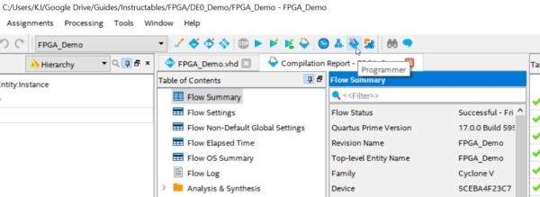
Step 10: Open the Programmer
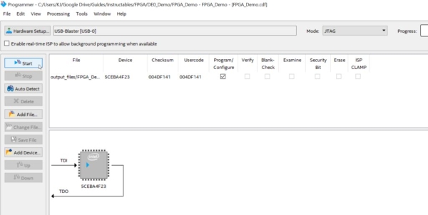
Step 11: Download Program to Chip
Step 12: Wrap-Up
Hopefully you should have a working circuit by now. FPGAs can be quite tricky so your setup may have created obstacles along the way. just post a comment and we’ll see if we can help out.
Tides. In Anchorage Alaska we live on a point located between two enormous tidal bays–so big in fact that Captain Cook on his initial survey of the area thought (hopeful thinking) that this entrance would prove to be a “northwest passage”. It is shallow and all boats traversing to the port are aware of the difficulties involved with a tidal basin considered to be the second largest tide flow in the world. Strangely enough when you go through a tunnel to another port not 1/2 hour away the tidal flow is the exact opposite from the high and low tides near anchorage. Tides are dependent on the moon, sun, configuration of the ocean floor and surrounding land masses–in other words they are complicated. Old tidal clocks attempted to simplify these arrangements by reducing the periods of high and low tides to the moon movements. This works in certain locations, but is generally useless for most areas. If you look up tidal calculations you find that NOAA has great tide tables: Tide Predictions – NOAA Tides & Currents. There is lots of software out there that runs on a computer to generate these tables: JTides Home Page – Arachnoid (this guy is super smart and his web site is wonderful!) But I wanted this thing to be solar-rechargeable, low energy, go unattended for years, not rely on tons of memory, and run by a microcontroller. So I found this guys website: http://lukemiller.org/index.php/2015/11/building-a-simple-tide-clock/ He was able to take the calculations for getting tide height and reduce them into algorithms that are microcontroller size comparable.
Step 1: Gather Your Materials
So there are a couple neat parts to this build. I built a solar powered conch screamer previously: https://www.instructables.com/id/Solar-Powered-Co… didn’t like the perched solar panel as part of the design–I wanted custom cells that would become part of the instruments practicality. So you have to buy small cells from eBay or amazon and glue them together which is really fun. I also wanted to use servo control for low energy, repeatability and no need for endpoint feedback with steppers. But due to the limitations of the control to about 180 degrees I had to build a gear chain to control the 360 degree movement. For low energy I went with the Adafruit TPL5111–which has an enable to ground pin that turns off the processor unit after setting the tide-time every two hours.
4. Adafruit PowerBoost 500 Basic – 5V USB Boost @ 500mA from 1.8V+
5. USB / DC / Solar Lithium Ion/Polymer charger – v2 Adafruit
6. HS-225BB Servo–servo city
7. 32P, 24T C1 Spline Servo Mount Gears (Acetyl)# of teeth60T–servo city
8. 1/4″ Bore 32 Pitch Shaft Mount Pinion Gears# of teeth32T–servo city
9. 1/4″ Stainless Steel D-ShaftingLength4.00″–servo city
10. Aoshike 100pcs 0.5 V Micro mini Solar cell for solar panel 52 x 19mm/2 x 3/4 inches Polycrystalline Silicon Photovoltaic Solar Cells Sun power for DIY Cell Phone Charger–Amazon
11. 1/8 inch x 55 yds Copper Foil Tape – (3mm x 50m) – EMI Shielding Conductive Adhesive–Amazon
13. Edge-Glued Round (Common: 1 in. x 17-3/4 in.; Actual: 1.0 in. x 17.75 in.)–Lowes
14. 18650 Lipo Battery and battery sled–Bangood
Step 2: Build Your Solar Panel
Well the first thing that you learn when you work with these solar cells is they’re fragile. I work with glass on a regular basis so I thought I would be used to fragile. But these are like potato chips–so buy some extras. Construction is basic–each cell produces 0.5 volt and you need about 6 volts to charge the lipo battery so you need 12 groups of cells in series. How many you put in parallel in each group is up to you and will determine how many mAmps you get on a sunny day. I went with three in each group–so 36 total cells. The back side of the cell is positive and the front is negative so when you join them its front to back for series and front to front and back to back for parallel. There are a million youtube videos on doing this with solder and special solder coated copper tacers but I found this not fun. So I used conductive adhesive copper strip to attach them together–it worked great. Solder the connections between groups of cells to make firm connections–this was the only point where I had failures with the sticky tape. Monitor your work carefully–putting the cell groups and then the whole unit under a grow light to check if voltage and mAmps output is correct through the whole process–failure is readily apparent. The neat thing about building with your own cells is you can design them in anyway you want–go wild with them–make a huge wave mosaic “The Great Wave off Kanagawa” or not. So when you want to lock things down connect the plus wire to the last back and minus wire to the last front and feed them through the board your building this on–I used a cheap unfinished round blank from Lowes. Surround it with a moat of tape and pour a couple layers of bartop clear epoxy to seal it all in. Then you can exhale as the chips are no longer fragile.
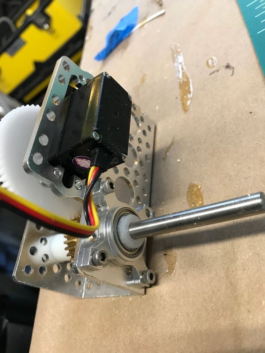
Step 3: Build the Servo Gear Train
You need about a two to one ratio of gears from the servo to your output shaft so that 180 servo control will be translated into 360 movement of the hand. So I chose the appropriate size gears from servo city. You have to check and make sure that your gear hub is designed to fit your servo–there are a large variety. The servo I used was a small but not micro–I found that too tiny was not good in this case. The gears had to be rather robust too. I mounted the servo and gears in one of the servo-city housings that seem to fit together so well. They also had an included bearing which makes the action smoother but is probably not necessary.
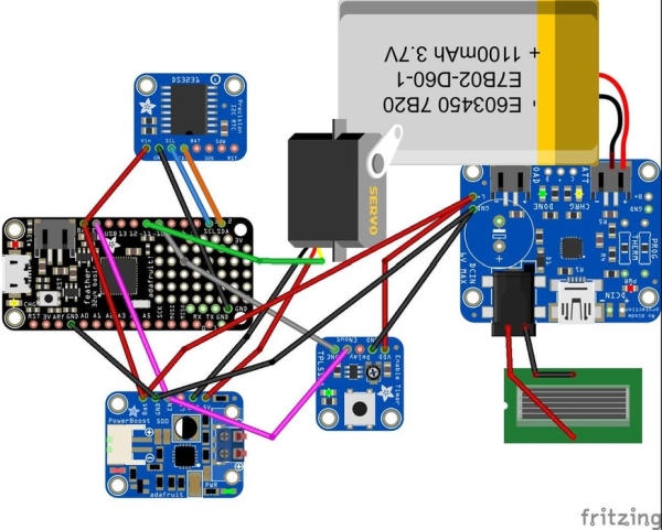
Step 4: Electronics
The electronics are best looked at on the Fritzing diagram. To get enough power through the possible long periods of light draught I used a 18650 battery with a sled to hold it. This was connected with a JST connector to the Adafruit Solar charge controller. The other input to this unit was the output from your beautiful solar array through a barrel connector. The output of this unit was distributed to the microcontroller, the Adafruit TPL 5111, and the boost device that powers the Servo. The 3.7 volts from the battery might be good enough for some servos but mine was stuttering quite a bit on this low power feed so I boosted it to 5 volts. The RTC is powered through the microcontroller. Pin 11 on the microcontroller is used to control the Servo. Pin 10 is used to signal the TPL 5111 that it needs to turn off power to everything by connecting the Enable pins on the microcontroller and Boost device to ground. The TPL 5111 is set to its maximum time between wakes of about 2 hours. I also put a slide switch on the TPL 5111 enable line that allowed me to trouble shoot and send new software out to the microcontroller without having it shut down. All the parts were assembled on a perf board.
Step 5: Putting It Together
I hollowed out the back of the board to accommodate the parts. A central large hole was drilled for the servo unit to sit in. The servo gear unit was mated with a aluminum shaft pointer that was painted for RED for high tide and BLUE for low tide and large ‘map pins’ were also placed on the front surface to delineate the hours and quarter hours. No attempt was made to make the parts waterproof but this could easily be done with a rear housing.
Step 6: Programming
If you go to http://lukemiller.org/index.php/2015/11/building-a-simple-tide-clock/ you will see what a wonderful job Luke Miller did with building the infrastructure to program this device. Using the RTC you obtain the current time and then get the current water height by using an TideCalc object called myTideCalc. You can get the software bones at: http://github.com/millerlp/Tide_calculator. Every tide station has an associated software library that you must download and include with my program in a library to have it function correctly. In this case I am using the library from the Sitka sound in southeast Alaska, but you will find a variety of locations that he has set up software for. My adaptation of his software is to enable the microcontroller to find the next high or low tide when it is powered up by the TPL 5111. It does this by slowly increasing the time by 15 minute intervals and measuring when the tide changes slope from positive to negative or negative to positive signaling high or low tide and then moving the servo to the appropriate spot on the dial. Every two hours the next high or low tide is checked for and the RED or BLUE end of the clock is moved into appropriate position. When initially setting the servo position you will have to check where your servo limits are on the dial and program them into the map and constrain functions in the software. The other tricky part is using writeMicroseconds instead of servoWrite commands to control servo function as the latter does not really give you 180 control for most servos! Another note is that the software is designed for regular time not daylight savings time so there is an if statement that modifies your output depending on where you live.
Nearly all of our wireless communication is done using radio waves*, including phone calls, text messages, and WiFi. With its built-in radio transmitters and receivers, the Micro:Bit microcontroller makes it super easy to build all sorts of projects with radio communication.
This particular project is a simple & quick way to send text messages between two Micro:Bit** microcontrollers – the sender writes a (short) message that is transmitted via radio to the receiving Micro:Bit, which shakes a lil’ puppet using a servo motor, and then displays the message on the Micro:Bit LED screen. Each Micro:Bit can be both a sender and receiver.
It’s sort of like a two-person Twitter.. if the tweet notified you via dancing cardboard robot puppet!
**A huge THANK YOU to Adafruit for donating the Micro:Bit microcontrollers used in this project for educational purposes! yayy thank you for supporting this educational endeavor!!
Step 1: Build a cardboard puppet like the one shown in the photo or create your own! Use the paper fasteners to make joints.
Step 2: Build a mounting system to attach the puppet to the servo with skewers and cardboard.
I used a magnet to attach the puppet to the servo mounting system because magnets are awesome, but you can also use glue, tape, velcro, or a variety of other adhesives!
Step 3: Build a stand for the puppet.
On an approx. 6 in. x 12 in. cardboard sheet, measure, mark, and cut a hole for the servo body so that the arms of the servo rest against the front of the cardboard sheet.
Cut two triangles out of cardboard and glue them on the back of the stand so that the stand, well, stands upright!
Cut a hole for the Micro:Bit wires to thread through and add two pushpins on the front to hold the Micro:Bit.
Step 3: Code the Two Micro:Bits!
To start, choose one Micro:Bit to be the sender and the other Micro:Bit to be the receiver. Once both are working as expected, add in the code for both roles.
Use the Make Code Micro:Bit website to program each Micro:Bit. As this is intended as a beginner project, the whole system can be built using the block-based programming language, although adaptations are encouraged and appreciated!
If there is more than one pair of Micro:Bits in the room (i.e. in a classroom setting), remember to set different radio group numbers for each pair.
The sender sends a (short) text based on user inputs over radio, like the example above. Pretty simple! The receiver moves the servo when an incoming text is received, then scrolls the message text on the LED screen, like in the example below.
Press the reset button to stop sending/receiving the incoming message.
Step 4: Connect the Servo!
Connect the servo red wire to the Micro:Bit 3V power pin, the servo black wire to Micro:Bit ground pin, and the servo white (or yellow) wire to the Micro:Bit input pin P0.
Step 5: Send All the Messages!
Program both Micro:Bits to be both a sender and a receiver so you can communicate back and forth. Then switch power from the laptop to the battery pack and test out your wireless communication system! When the sender sends a message, the puppet will notify you to check the LED screen so that you can see the incoming message.
How far of a range can you get? Test it out!
There are tons of other extensions to this introductory project, here are some possibilities:
Add more message options by adding more inputs or changing how those inputs are read;
Instead of a table-top alert system, build a wearable alert system;
Theremin are those unique instruments use to make those alien show theme songs or sound effect. You may have also heard it in Star Trek, Big Bang Theory, or even a haunted house. They produced a unique sound from the electromagnetic effects between wires.
Here we will duplicate a similar sound digitally using a buzzer controlled by Pulse Width Modulations and an Light Dependent Resistor (LDR) for the input of reading values as the hand moves over it.
Step 1: BoM
* ESP32
* Light Dependent Resistor (LDR)
* Buzzer
* Jumper Wires
* Breadboard
Step 2: Soldering
We will solder a voltage divider onto the LDR to make the wiring simpler.
* Take a 10kΩ resistor and solder it to one of the pins of the LDR.
* Then take two different coloured wires and solder it to each pin of the LDR.
That’s it! Now you have a voltage divider!
Step 3: Wiring
Follow the following table when wiring the LDR and Buzzer to the ESP32:
I/O
Pin #
ESP32 Pin #
Buzzer*
1
D4
Buzzer*
2
GND
LDR
Resistor
D5
LDR
Grey
3.3V
LDR
Red
GND
* Order is arbitrary
Step 4: Code
int photopin = 5; // Pin where the photo resistor is connected to
int photValue; // The analog reading from the photoresistor
int buzzerPin = 4; // Connect Buzzer to Pin 4
long buzzerFreq; // The frequency to buzz the buzzer
// You can experiment with these values:
long buzzMAX = 2500; // Maximum frequency for the buzzer
long photoMAX = 1023; // Maximum value for the photoresistor
void setup() {
    pinMode(buzzerPin, OUTPUT); // set a pin for buzzer output
}
void loop() {
    // read the values of the potentiometer
    photValue = analogRead(photopin); // Values 0-1023
    // normalize the readings of a photoresistor to thatof the buzzer and photoresistor
    buzzerFreq = (photValue * buzzMAX) / photoMAX;
buzz(buzzerPin, buzzerFreq, 10);
}
void buzz(int targetPin, long frequency, long length) {
long delayValue = 1000000/frequency/2;
long numCycles = frequency * length/ 1000;
for (long i=0; i < numCycles; i++){
digitalWrite(targetPin,HIGH);
delayMicroseconds(delayValue);
digitalWrite(targetPin,LOW);
delayMicroseconds(delayValue);
}
}
Step 5: Enjoy!
It’s easy to use but takes a lifetime to master and to play good music. Move your hands over the LDR to change the tone.
In this indestructible I will demonstrate how to make your Own Solar power Monitoring station .With materials ,Code and electronics parts. we will start with the PCB designed on a fritzing program to sending off for the PCB ,Soldering it and Installing it into a junction Box , then we will Build the solar Junction Box and install the components and power up everything ,Run some simple code and start monitoring
www.penteon.io (Particle Power Shield with monitoring capability )
Step 1: PCB Design
The Program I used is called Fritizing ..Http://www.fritzing.org you can download and install a PCB design program which is free to use ..You can even order the PCB’s directly from the program if you wish or export it as a gerber file for any PCB manufacturer depending on where you live. I went for a company called PCBWay.(PCBWay.com) they are an excellent company who manufacture any PCB you can design ..The turn around from Ordering to delivery into the heart of Canada was 6 days ..Cool huh The design was simple ..I wanted to be able to power the board with either 18-30 Volts AC or 12-30 Volts DC ..I wanted screw terminals because these are going to be deployed all over the place and I need a perminant solution … I added a temperature sensor , Current sensor , and a voltage divider circuit to monitor the Solar output and battery state ,and 2 relays controlled by the Micro Controllers through an NPN transistor. I used a microcontroller called a Particle ..http://particle.io ..These are a great DIY device with Wifi or if you wish cellular connectivity The electronic parts I purchased from digikey ..www.digikey.ca or www.digikey.com ..They are a parts wholesaler with everything you would need
Step 2: Soldering the PCB
Here is a soldering tutorial. For many soldering is scary and a real challenge and I hope this helps for todos you will need 1. A good soldering iron 60 Watts is plenty…Amazon.ca or Amazon.com is a good start 2. No Clean solder smaller the solder the easier it is to work with 3. A good set of cutters ..Amazon.ca or Amazon.com 4. PCB holder is handy but not necessary 5. Flux(cleaning agent for soldering tiny parts or non through hole pieces (I will demonstrate) 6. Wet sponge 7. Steady hand
Ok now if your ready have all your parts on hand ..Start from the inside to the outside ..Going slowly and methodically insert the pieces and solder them one by one. I found it handy to have the soldering iron hot and ready to go ..Just touch the board and the piece to be soldered momentarily and add a little bit of solder to the piece and the iron at the same time ..it takes a bit of practice but once you get it ..it’s easy. Follow the pictures I’ll post them in order..Hope it helps
Step 3: Junction Box Design and Integration of the Parts
For building an effective junction Box lay out all your Materials and equipment and place everything on the back box ensuring you have enough space for everything.
You will need
1. Battery operated Drill
2. Hex head self tapping screws 3/4″
3.Hex head driver
4.Hacksaw for cutting (din rail )
5.Step bit for drilling holes on the bottom of the box
6.Safety glasses and Gloves (You are working with sharp tools and flying debris…Better to be safe than blind and bleeding )
Most hardware stores have everything you need for the install..Most electrical supply stores have everything else.
Step 4: Building Your Solar Array
Your Going to need some things
1.Solar Panel..
you can source what size of panel you need by researching what the Watts of the Device or devices you are powering ..Rule of thumb ..ie 60 Watt light bulb x 12 hours a day =720 watt hours of battery usage x 4 days backup ..1200 Watt solar panel 4×12 Volt 100Ah batteries should suffice
2. …
the battery is what you are going to power you systems when its dark so you need to size it accordingly I recommend at least 4 days usage without sun ..you never want to completely drain your battery ..it will cause wear and tear and you will end up replacing it sooner than later ie ..30 watt hours x 4 days = 1200 watt hours of battery’s .
3. Charge controller ..
The Charge controller must be sized for charging amps and panel voltage ..If you need help there are many resources ..A typical Solar 12 volt solar panel will put out about 30 Volts DC in direct sunlight..
NOTE..The Solar panel will immediately produce voltage in sunlight or daylight so care is needed
4. Wiring ..You should size your wiring to handle the load of your System ..#14 is NOT good for 30 amps #10 is good for 30 amps..I recommend at least #10 30 Amp rated wiring from your panels to the charge controller and Battery
5.Protecting your wiring …
I recommend a flexible non metalic conduit and connectors to interconnect you devices (NEVER JUST RUN THE WIRES OPEN AIR) it will wear eventually and sun and rain will cause degradation .
Step 5: Powering Up the Solar Array and Voltage Measurement
Step 6: The CODE , MONITORING and Alarms
For the monitoring and alarms I used …. 1. Librato Monitoring (https://www.librato.com) 1 month trial free 2.Particle IDE (Http://www.particle.io) free 3.Twillio (https://www.twilio.com) free trail SMS service
Create your own Interactive LED Beer Pong Table! This instructable will guide you through all of the steps to in order to create a one-of-a-kind beer pong table complete with cup detecting RGB pods, automatic ball washers, a 32×12 ping pong ball LED grid, side LED rings for spectators and an RF interface to communicate wirelessly with a PC! It will teach you everything from theory of operation to modifying the table to suit your needs. First, I will take you through the modification and wiring of the table before we dive into the software side of things.
The toughest part about this project is just getting it started. There is a lot of prepping and labour to do before you can get anything real exciting working. However, if you can stick it out until you get the 32×12 LED grid in place, you will do just fine. Once you get up to that point, you can really start to see the potential for the table and it makes working on it a lot more enjoyable. I worked on this table on and off over the course of one year. If I were to build another one and had a set schedule of 8-hours per day to work on it, I could easily finish it within one week. The majority of the time that I spent on this project went into prototyping, development and writing the software rather than actually assembling the project.
Now come and take a tour with me through this Instructable and let us find out if you are up for the challenge!
Final Update I have published a new Instructable that details the operation of the X5 kit and its capabilities. Although I modified the size of the table in the new Instructable, the X5 kit can handle everything that this version can do as well as more. In otherwords, customize your table however you like, whether you build off of this tables layout, the new tables layout or you completely design your own table layout. Thank you to everyone who has been patient with me! There was a lot of time needed to completely re-design the electronics and go through a few revisions before I had a solid product. Cheers!
Step 1: Intro: Gallery
Before we get started we are going to need a little bit of motivation, take a look at these pictures and realize what you will be making. This project is not for the faint of heart, not because it’s difficult, but because it is very tedious and time consuming. Any time that you get frustrated while making this project, take a deep breath, come back to this step, take a look at the pictures and remember what you are working towards!
The pictures and videos that I took don’t even do the table justice either, it really is something else to see up close and personal. The reward outweighs the risk and this one-of-a-kind project is definitely worth building! But we’ve got a long road ahead of us so lets get to it!
Step 2: Theory: What Is Beer Pong?
Beer pong is a drinking game in which players throw a ping pong ball across a table and try to hit one of the ten 1/3 filled beer cups on the other side. Once a cup has been hit, the beer is drank from it and it is removed from the table. The first team to clear the opposing teams cups wins the game. Although it is called beer pong, the game can be played with any beverage in the cups such as beer, juice or water. In fact, the World Series of Beer Pong (WSOBP) has switched to only using water in its tournaments so that they abide with all laws and regulations for playing beer pong in bars and public places.
There are many variations to the game so it is a good idea to go over the rules with each team so that each player knows what rules apply before the game begins. If you are unfamiliar with the game of Beer Pong, check out the link below.
Now before we start building this project we should get a little bit of theory under our belts! The playing surface on this beer pong table is a 2’x8′ Lexan sheet which is considered regulation size. There is 6 inches of extra table on each side of the Lexan sheet which is only used for spectators and their drinks, giving the table a total size of 3’x8′.
The table contains 384 individually controlled LEDs with half of a ping pong ball over top of each LED, 20 RGB Pods that are able to detect whether a cup is over top of the pod and 2 ball washers that will pump a ping pong ball from one side of the table to the other with water, clean it, then blow it back up so that the player can grab it. On each side of the playing surface, we have a 6 inch wooden rail with 4 LED rings per rail and two LED rings for each ball washer.
I have attached a PDF of my AutoCAD drawing seeing as the jpg file isn’t very clear. You will want to print this sheet out and use it for reference when we are modifying the table. I have also attached the AutoCAD 2012 file if you need to modify the table to suit your needs. You may notice that the creation date on that file is August 16, 2011. I actually designed this table and demoed the RGB pods, ball washers and LED grid quite a few years ago. I had just never got around to building the table and integrating all of the features together up until one year ago.
32×12 LED Grid In the center of the table we can create any animation that will fit into a 32×12 pixel grid. We are able to display scrolling text across it, watch a pong animation, display a sine wave, display the score of the game, etc. There is a huge amount of possibilities! Since we are able to detect when a cup is removed from the table we can make specific animations that trigger exactly when that happens. We’ll get more in-depth with that later.
20x RGB Pods w/ Infrared Sensors At each end of the table you will see 10 pods. The 16oz cups that are used for beer pong are placed over top of these pods. Each pod contains 4x RGB LEDs and 1x infrared sensor and we are able to light up the pods with any color that we would like. The infrared sensor will detect whether or not a cup is over top of the pod, so if a cup is removed we can change the color of the pod, begin an animation on the LED grid, run an animation on the RGB pods, etc.
Ball Washers There is a ball washer on each side of the table. The purpose of the ball washers are to…wash the ping pong balls (who would have thought, right!?). The 4x cyan colored holes on the AutoCAD drawing are used to mark the ball washer placement. A player drops a ball into the ball washer hole that is to their left, an infrared sensor will detect the ball and activate the water pump, the water will then push the ball down the pipe while cleaning it, all of the water will be strained out before the end of the pipe and then a fan will turn on and blow the ping pong ball up and out of the ball washer hole to the right of the player. Once the ball is grabbed by the player, the infrared sensor on the right side of the ball washer will detect that the ball is gone and shut off. Each ball washer hole also has a LED ring around it that can be used for animations.
LED Rings There are a total of 12 LED rings on the beer pong table. The outer railing of the table contains 8 LED rings and the ball washers use the other 4. Much like the 32×12 LED grid, the LED rings are just used for animations. They can be set to go in accordance with music (VU Meter feature must be turned on), fade in and out, flash rapidly or any other cool animation that you can think of. Beer cups can be set inside of the LED rings on the railing which provides a cool effect on the upper lip of the cup.
VU Meter I have implemented a microphone and an audio amplifier which feeds into the ADC on the microcontroller so that we are able to detect different intensities of sound with the microcontroller. This really adds to the effect of the table and looks really cool as you can turn on different features of the table to different intensities of sound, display a VU Meter on the LED grid and much much more.
RF Module I have added support for an nRF24L01+ RF module on this beer pong table so that we can control the beer pong table from a laptop. We can send text from the PC to scroll across the LED grid, we can individually select the color of each RGB pod, we are able to set the grid brightness, etc. Seeing as I am still learning the USB protocol, I do not feel comfortable posting my PC software source code yet as it is still really messy and may contain a few bugs. When I get it cleaned up I will be sure to post it! Not a big deal though, I have posted the RF transmitter source code, the PC executable and the source code for the beer pong table in step #82 so that we can still test it out.
The cost to make this beer pong table is around the $400 – $500 mark. The major costs are the 2’x8′ 1/8″ Lexan sheet which was $83, the table itself which was $30 (I got a good deal on a used one) and the 500′ feet of CAT5 (you won’t use all of the CAT5, better to have too much than not enough though) which you should be able to find for $30 – $60. Seeing as I worked on this project over the course of a year, I purchased everything that I needed at different times throughout the year. I never had to fork over $400 at once, just $50 here and $50 there, so it didn’t seem as expensive at the time.
This was just a brief overview of the table. We will go much more in-depth as we get to each feature that is available to us. Take a deep breath, in the next few steps we are going to prepare for construction!
Step 4: Preparation: Skills and Software Required
If you look at this project as a whole it may seem very intimidating. The trick is to break each part down into ‘mini’ projects and integrate them together. You don’t build the whole project, wire everything together and then turn it on hoping that it will all work because chances are that it won’t. Instead, we take baby steps and separate the project into smaller sub-projects, testing the workings of each sub-project before moving on to the next one. By doing it this way you can work out any issues one at a time as you progress.
The following knowledge and skills will help aid you through this project.
An understanding of digital electronics (multiplexing, data transfer, etc)
An understanding of C Programming (The whole project is written in C with MPLAB’s C30 Compiler)
An understanding of binary and hexadecimal numbering systems
How to solder (This includes SMD components)
How to crimp ends and create connectors (RJ45, Molex, etc)
How to use test instruments such as a multimeter
How to operate power tools (table saw, drill, jigsaw, etc)
How to create PCBs or set up circuits on veroboard
If you are not good at soldering SMD components you may want to get somebody who is good at it to help you. The PIC24HJ128GP506A has 64-pins that are 0.22mm wide and only have a 0.28mm space between pins.
Software All of the software for the beer pong table has been written in C. You will need to download the MPLAB IDE and install it, as well as the C30 compiler to go with it. If you plan on using the RF feature of this table, you will also need the C18 compiler as the RF Master Board uses a PIC18F4550 to control USB and wireless operation.
Step 5: Preparation: Electronic Components
There are 24 PCBs that are required to create this project. Now, 20 of those PCBs are actually single RGB Pods that are placed under the cups (10 on each side). There is then 2 RGB Pod controllers (1x for each side of the table), the 32×12 LED grid controller PCB and the Master PCB which contains the microcontroller. I have created a component list for each category and added up the total amount of components that are needed to assemble the required amount of PCBs in that category.
The majority of these components can be found on eBay but there are a select few which may prove more difficult to find. I have attached a Bill Of Materials to this step which has each component, the required quantity, the price and the vendor where the component(s) can be purchased. The total bill for all of the components (including both power supplies and blue LEDs) listed below comes to $154.66.
Power 1x 12V 5A Power Supply (I used a 12V 10A power supply, only a 5A is needed) 1x 5V 5A Power Supply (I used a 5V 10A power supply, only a 5A is needed) 1x 120V Power Bar 2x 24″ 120V Power Cords
32×12 LED Grid Controller (1x PCB)
2x HT1632C LED Drivers
1x 2.1mm Power Jack
2x Quad RJ45 PCB Mounted Jacks
3x Single RJ45 PCB Mounted Jacks
16x Quad 150Ω 0603 SMD Resistor Networks
500x 5mm Blue LEDs (these are not on the PCB, they are mounted on the table)
The passive components and connectors I usually purchase from DIPMicro or eBay. Many of the components/connectors can be changed according to what the user likes, the footprints might just not match the PCB layout. If you are breadboarding or point to point soldering everything together then this wouldn’t be a problem.