Okay, I admit I don’t have a monkey. But would you be looking at this if I didn’t mention monkey? And this would work for a monkey.
Does your monkey or dog wander off? Would you like to see where he/she is? Well, they make dog trackers (see picture). However, most are over $100 and require a monthly tracking service fee.
So this Lazy Old Geek (L.O.G.) decided to make my own. This requires a collar module (see picture) and a display module (see picture).
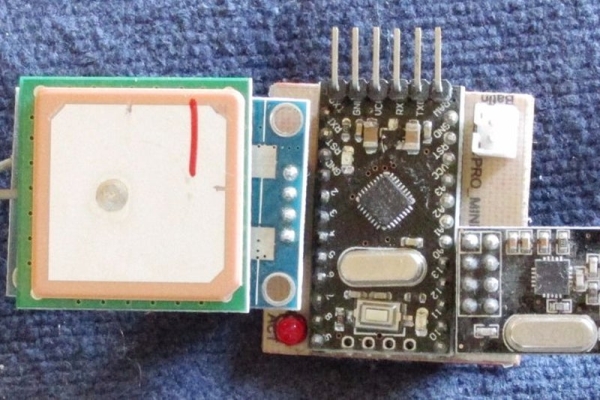
HowItWorks: The collar module is battery-powered based on Arduino, has a GPS module and an nrf24L01+ transceiver to talk to the display module. The display module is battery-powered based on Arduino, has a GPS module and an nrf24L01+ transceiver to talk to the collar. It also has a compass module and an LCD display. The collar transmits its GPS coordinates and battery voltage to the display. The display module calculates its own GPS coordinates and calculates the distance and direction between the two. The LCD shows which direction the collar is and the distance between the two.
Step 1: Collar Module
What It Does: The GPS calculates the location of itself and sends it to its Arduino. The Arduino sends this information along with the battery voltage to the nrf24L01+ module which broadcasts it wirelessly (to the display module).
The collar module consists of four major components:
A Ublox NEO-6M GPS (see picture)
An 8MHz 3.3V Arduino Pro Mini (see picture)
An nrf24L01+ wireless transceiver (see picture)
A Lithium battery (see pictures)
There’s also a custom made PCB, an LED, some connectors.
For my battery-powered Arduino projects, I’m standardizing on JST2.0 2 pin connectors for power. The four main components can be bought on ebay for a good price.
I wrote an Instructable on setting up the Ublox NEO-6M GPS:
For the battery, I selected a 3.7Vdc Lithium Ion battery also bought on ebay. This is a common size for replacement batteries for some smartphones and tablets. These come in various sizes and capacities. I had to solder a JST2.0 connector to the batteries. I hadn’t really decided on which one to use.
I also purchased a USB Li Ion 1A battery charger and added a JST2.0 connector to charge these batteries (see picture).
Warning: The standard USB port on a computer will often only put out 0.5A. While this will work, it will take longer. The charging will be faster if a 1 or 2A source is available, such as a USB 2A AC adapter.
I designed the PCB to connect the components. (see schematic) R1 and R2 form a voltage divider to monitor the battery voltage.
Technobabble: The technically inclined may notice that there is no voltage regulator in this design. While Li Ion batteries are nominally rated at 3.7Vdc, depending on the charge they will actually vary from about 4.2Vdc down to about 3.0Vdc. This Arduino Pro should operate from 1.8 to 6Vdc. The nrf24L01 from 1.9V to 3.6V. And the Ublox neo-6M 3V to 5V. So everything should work down to about 3V which is probably limit I want to discharge Li-ion battery.
Eagle cadsoft files for both the collar(PetTrackee) and the base(PetTrackerBase) are attached.
Step 2: Display Module
What It Does: The nrf24L01+ receives the GPS and battery voltage from the collar module.
The internal GPS calculates the location of itself. The Arduino calculates the distance and direction between the two GPSs. The LSM303DLHC magnetometer is an electronic compass. It is used to find out where North is so that the display will point towards the collar module. The distance will also be displayed.
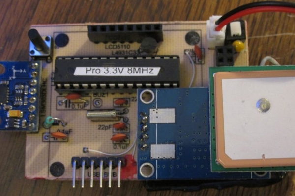
The display module consists of several major components:
A Ublox NEO-6M GPS
An nrf24L01+ wireless transceiver
An LSM303DLHC magnetometer (3.3Vdc)
An LCD5110 display (3.3Vdc)
A custom Arduino PCB
A Lithium battery (see pictures under collar module step)
Arduino PCB schematic is attached. Power is regulated with a 3.3Vdc regulator. U$1 is a pushbutton on/off switch:
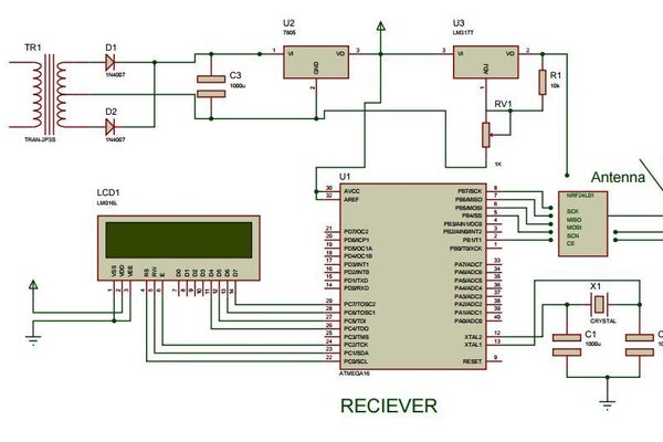
This Project is Based on Atmel’s Atmega16 Microcontroller as the main brain for computation.
NRF24L01+ Wireless communication module is used for the Wireless data transmission.
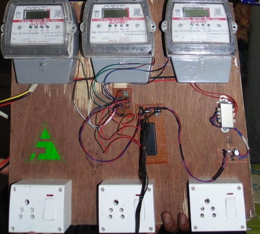
Today we have hundreds and thousands of Energy Meter installed in an Apartment Complex , Shopping Mall, School, University , Hostels and Lot more. The problem arises when meter is read by an employee to compute the bill per Energy Meter. Its require lot of manpower and cost.
Here I have come up with a simple project that will save manpower and cost by automatically transmitting the Energy count of multiple Energy meter to the Host Or Service provider.
I have taken he data from Three Energy meter and transmitted the Data to the receiver, which computed the load and the the total consumption per meter.
If the load exceeds the permissible level then a buzzer starts.
Data gets saved in sender’s side so no data loss is produced if the receiver is switched off or connectivity is lost.
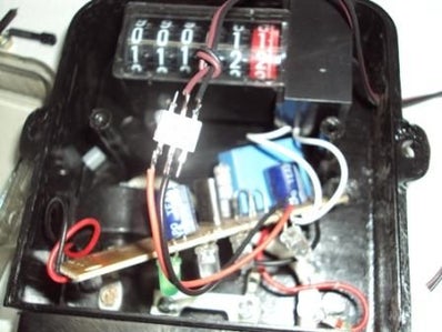
4. Connect the Cathode of the LED to the Pin1 of the Opto-coupler (MCT2E) and the other end of the LED to the Pin2 of the Opto-coupler
5. Connect pin 4 of the opto-coupler to a Black wire and Pin5 to the brown wire. Connect the Black wire to the ground of the circuit board for the projects Prepaid energy meter or Auto meter reading projects. The Brown wire carry’s the pulse output.
6. Connect the power supply and load as per this picture.
Step 2: Basic Algo for Calculation
Here meter is interfaced with microcontroller through the pulse that is always blinked on the meter. Further that pulse is calculated as per its blinking period, using this principle we calculated it for one unit and accordingly what charge will be for a unit.
After 0.3125 watt energy uses Meter LED (calibrate) blinks. Means if we use 100 watt bulb for a minute then the pulse will blink 5.3 times in a minute. And this can be calculates using given formula.
The nRF24L01 module is an awesome RF module that works on the 2,4 GHz band and is perfect for wireless communication in a house because it will penetrate even thick concrete walls. The nRF24L01 does all the hard programming fore you, and even has a function to automatically check if the transmitted data is received at the other end.There are a couple of different versions of the nRF-family chips and they all seem to work in a similar way. I have for example used the nRF905 (433MHz) module with allmost the same code as I use on the nRF24L01 and the nRF24L01+ without any problems. These little modules has an impressive range, with some versions that manages up to 1000 m (free sight) communication and up to 2000 m with a biquad antenna.
nRF24L01 versus nRF24L01+
The (+) version is the new updated version of the chip and supports data rate of 1 Mbps, 2 Mbps and a “long distance mode” of 250 kbps which is very useful when you want to extend the broadcast length.The older nRF24L01 (which i have used in my previous posts) only support 1 Mbps or 2 Mbps data rate.Both the models are compatible with each other, as long as they are set to the same data rate. Since they both costs about the same (close to nothing) I would recommend you to buy the + version!
Part one – SetupConnection differencesThe nRF24L01 module has 10 connectors and the + version has 8. The difference is that the + version instead of having two 3,3 V and two GND, have its ground (the one with a white square around it) and 3,3 V supply, next to each other. If changing module from a new + version to an old one, make sure not to forget to move the GND cable to the right place, otherwise it will shorten out your circuit. Here is a picture of the + version (top view), where you can see all the connections labeled. The old version has two GND connections at the very top instead of at the down right corner.
Power supply (GND & VCC)The module has to be powered with 3,3 V and cannot be powered by a 5 V power supply! Since it takes very little current I use a linear regulator to drop the voltage down to 3,3 V.To make things a little easier for us, the chip can handle 5 V on the i/O ports, which is nice since it would be a pain to regulate down all the i/O cables from the AVR chip.Chip Enable (CE)Is used when to either send the data (transmitter) or start receive data (receiver).The CE-pin is connected to any unused i/O port on the AVR and is set as output (set bit to one in the DDx register where x is the port letter.)Atmega88: PB1, ATtiny26: PA0, ATtiny85: PB3SPI Chip Select (CSN)Also known as “Ship select not”. The CSN-pin is also connected to any unused i/O port on the AVR and set to output. The CSN pin is held high at all the time except for when to send a SPI-command from the AVR to the nRF.Atmega88: PB2, ATtiny26: PA1, ATtiny85: PB4SPI Clock (SCK)This is the serial clock. The SCK connects to the SCK-pin on the AVR.Atmega88: PB5, ATtiny26: PB2, ATtiny85: PB2SPI Master output Slave input (MOSI or MO)This is the data line in the SPI system.If your AVR chip supports SPI-transfere like the Atmega88, this connects to MOSI on the AVR as well and is set as output.On AVR’s that lacks SPI, like the ATtiny26 and ATtiny85 they come with USI instead, and the datasheet it says:”The USI Three-wire mode is compliant to the Serial Peripheral Interface (SPI) mode 0 and 1, butdoes not have the slave select (SS) pin functionality. However, this feature can be implementedin software if necessary” The “SS” refered to is the same as “CSN”And after some research i found this blog that helped me allot.To get the USI to SPI up and running I found out that I had to connect the MOSI pin from the nRF to the MISO pin on the AVR and set it as output.Atmega88: PB3, ATtiny26: PB1, ATtiny85: PB1SPI Master input Slave output (MISO or MI)This is the data line in the SPI system.If your AVR chip supports SPI-transfere like the Atmega88, this connects to MISO on the AVR and this one stays as an input.To get it working on the ATtiny26 and ATtiny85, i had to use USI as mentioned above. This only worked when I connected the MISO pin on the nRF to the MOSI pin on the AVR and set it as input and enable internal pullup.Atmega88: PB4, ATtiny26: PB0, ATtiny85: PB0Interrupt Request (IRQ)The IRQ pin is not necessary, but a great way of knowing when something has happened to the nRF. you can for example tell the nRF to set set the IRQ high when a package is received, or when a successful transmission is completed. Very useful!If your AVR has more than 8 pins and an available interrupt-pin i would highly suggest you to connect the IRQ to that one and setup an interrupt request.Atmega88: PD2, ATtiny26: PB6, ATtiny85: –
Step 4: Basic Connection Diagram
This Connection diagram is a schematic
Step 5: Code
For CODE Visit GitHub https://github.com/arnabdasbwn
Universal transmitter to control everything! One transmitter to rule them all.
The Devo 10 is a programmable radio transmitter from Walkera. When Deviation is installed with a couple of RF modules, it can almost replace every transmitter for your RTF micro multi-rotors/quadcopters/helicopters and planes. In this video, I show how to mod it with a few parts and flash it with Deviation firmware.
This mod makes the Devo 10 compatible with many protocols including: Spektrum DSM2/DSMX (Blade/E-Flite) FlySky Hubsan Syma WLToys HiSky KN YD … more
I created a poster for Halloween event for kids. It can be a guessing game about what kind of animal they are pretending to be by looking at the mask or by clicking the button next to the animal to hear the sound of a animal on the mask.
Make the button big enough so kids can tab on it easily.
Step 2: Tape the Foil(or Any Material That Conduct Electricity) on the Back Side of the Poster
In order to connect the button to Makey Makey, first cutout the button part from the poster. And on the back side of the poster, tape the foil from button part to near Makey Makey. (Make sure the foils doesn’t overlap each other.)
Select a keys to connect from Makey Makey for each buttons. I chose “w, a, s, d, f, g” keyboard keys from left side(Blue Section from image) of the Makey Makey.
Plug the wire to all 6 holes and tape each wire to the tip of the each tin foils.
Last but not least, plug one wire to bottom side (Ground Section from image) on Makey Makey, so this will be the button that kids will press or hold while they tap the buttons in the poster with other hand. This last wire will allow to close the circuit, which means you will be able to transfer electricity from Makey Makey to all the buttons.
Step 3: Connect Rasberry Pi and Speaker (or Computer)
In order to play the animal sound we need connect Makey Makey to power source like computer or we can use Raspberry Pi (mini computer) and small speaker to fit in back side of the poster like in the image. I used black foam board to make a space where I could place the Raspberry Pi and a speaker.
Connect the USB cable from Makey Makey’s USB connector (Pink section) to Raspberry Pi’s USB port (top right section from image)
Connect the speaker to Raspberry Pi’s audio jack.
Step 4: Program to Play a Animal Sound With Scratch
I used simple visual programming tool called scratch.
In Scratch, I just dragged “Event” and “Sound” Blocks to connect keyboard keys to sound, so for example if “w” is pressed then play a sound “zebra”. (I uploaded all the animal sound to Scratch before I made the command.) Download the project from Scratch.
After Scratch project is uploaded or selected from Raspberry Pi’s browser, you can unplug the computer and just use USB charger for power source by connecting to micro USB port of Raspberry Pi.
WiFi has become an integral part of our life and daily billions of people use WiFi as a method to access the internet. But the range of WiFi is limited, unlike a cellular connection. A normal WiFi router usually has a range of about a 100m in clear sight and about 20m to 50m without clear sight (With walls or any other electronic appliance).
It would great to know the WiFi coverage of your Wireless router so you can place your router in a place at which you would usually get maximum range. The Ideal way to do it is to use a WiFi meter those devices are expensive and not easy to find.
So in this instructable I’m going to show you How to build a WiFi Signal Strength meter using the Particle Photon. If you don’t know what the particle photon is or if you are getting started with the particle photon I would recommend you to check out my previous instructables and also the documentation at the particles website.
The Particle Photon uses an online based IDE to upload code to the photon using OTA Updates. To upload any code to the Photon you will need to get it connected to the Particle Cloud server from where you can program it.
To get it connected to the particle cloud server, you will need an active internet connection and an existing WiFi network.
Next on your smart phone download the Particle.io application and install it. Once it is installed go to particle.io and signup for a new account or if you have an existing account you can skip this part. Next login to your account on the Smart Phone application and you should be presented with the home screen. On the Home screen select add a new photon and follow the on screen Instructions.
Once you have connected the photon to the internet, the on board LED will breath Cyan and you can proceed to the next step.
Step 3: Circuit
The circuit is quite simple, all you have to do is connect the OLED screen to the photon and there are two ways to do this depending on the OLED board you purchased. The 128×64 OLED screens come in two variants an SPI version and an I2C version.
If you are using the SPI version the connection goes as follows.
Particle Photon ————— OLED Display
Pin D0 – DC pin of the OLED Display
Pin D1 – Rst or reset pin of the OLED Display
Pin D2 – D1 pin of the OLED Display
Pin D3 – D2 pin of the OLED
3V3 Pin – VCC of the OLED
Gnd – GND pin of the OLED
IF you are using the I2C version of the OLED the connetion is as follows
Particle Photon ————— OLED Display
3V3 Pin – VCC of the OLED Gnd – GND pin of the OLED
Pin D1 – SCL pin of the OLED
Pin D2 – SDA pin of the OLED\
After the connections you can proceed to the next step.
Step 4: Testing
Before going to the actual design lets test out some test code, to verify that you have made all the connections right and everything is working fine.
The Below code will display the message HI I’m thepaticleguy you can edit this to your preference, the lines to edit in the code can be found in the loop part at the end of the program.
A voice controlled robot takes specified command in the form of voice. Whatever the command is given through voice module or Bluetooth module, it is decoded by the existing controller and hence the given command is executed.
Here in this project, I have used Bluetooth module and Android application to give voice command in the form of hex code. There are certain digits which can be sent directly to the Bluetooth module and automatically the digit is converted into its hex code.
We can use these digits as a voice command for the specified operation pre-programmed in the microcontroller. Using digits as a voice command is easier than using alphabetical commands.
Components required :
1.Microcontroller(AT89S52)
2.40 pin female socket for controller
3. Zero PCB board
4.Crystal oscillator(11.0592 MHz)
5.7805 voltage regulator
6.Relamate pin
7.Shift register
8.Switch
9.Resistance (1 K-ohm)
10.Capacitor (10uF,22pF(2))
11.L293D Driver with female socket
12.16×2 LCD
13.LEDs
14.Bluetooth module (HC-05)
15.Battery (12V)
16.Connecting wires
17.Soldering iron
18.Motors (required rpm)
19.Chasis for robot
20.Wheels
Step 1: Chassis Design
Design a chassis according to your requirement and need.
I have designed the chassis which is a lego chassis and easily available in the market.
Step 2: Connection and PCB Design
Circuit diagram for 8051, voice controlled the robot.
The connections on the PCB is supposed to be done according to the given circuit diagram.
Step 3: Program Code and Hex Code
Assembly Code for those who want to code in assembly language of 8051.
Using Keil Software you can write these Assembly codes for 8051 and generate hex file which is required to burn(upload) on 8051. For uploading (Burn) you need an 8051 burner, which you can find in your colleges or you can buy from the market.
Step 4: Android App
For sending voice command (1,2,3,4,5,6,7,8,9,0) to Bluetooth in the form of hex code a app is available in google play store named – Amr Voice.
In recent days, automatic fire detection and control is becoming very essential to reduce the fire in a building or an industry. It provides real-time surveillance, monitoring and automatic alarm. A key aspect of such systems is to identify a developing fire emergency in a timely manner, and to alert the building’s occupants and nearby fire stations.
In this Instructable, we will learn how to create a low cost fire detection system in which different subsystems communicates with each other over the Internet. This project is a combination of electronic circuits, programming and networking mechanisms working together to detect the presence of fire and provides an alert through a visual medium. Furthermore, the usage of light weight MQTT protocol aids in (almost) real-time execution and parsing of the critical data.
In this project, we consider an example of an organization which has one headquarters(HQ) and four sister institutions. All five firms of the organization has a control room each to monitor the fire status of the sister institutions. All control rooms receive the fire status of the four sister institutions and visually alerts the control room personnel by the glowing of respective LED (for eg., if there is a fire emergency in Institution 1, then LED 1 in all the control rooms glows). At the sister institutions, fire is detected using infrared sensors (Note: Hot objects emit Infrared Rays). The communication between the control rooms are performed using the MQTT protocol. The control room at the sister institutions are based on NodeMCU and acts as a node in the network. On the other hand, the control room at the HQ is equipped with a Raspberry Pi and acts as a broker. To display the fire status, another instance of a node is created at the Raspberry Pi.
This project brushes over the following topics:
SSH Raspberry Pi
Raspberry Pi as an MQTT broker
Port Forwarding
NodeMCU as publisher and subscriber
Raspberry Pi as a subscriber
File transfer over IP address (SFTP)
Step 1: Materials Required
LEDs x 20
Resistor x 5
NodeMCU x 4
Raspberry PI 2 x 1
Ethernet Cable x 1
Network Router with Internet Connectivity x 1
Breadboards x 9
Infrared Sensors x 4
Micro USB Cable x 5
Wires (Male to Male, Male to Female)
Step 2: Enable SSH on Raspberry Pi
Communicating with Pi using SSH has the following advantages:
Connecting peripherals like keyboard and mouse on Pi can be avoided.
We can work on Pi remotely.
By default, SSH service on Raspberry Pi is turned off. To enable this service, the following steps are done:
1. Type the following command on the terminal
$ sudo raspi-config
(Note: You may enter $ sudo -i to enable root access for the user)
2. Select ‘Interfacing Options‘ (#5) on the window that pops up.
3. Select ‘SSH‘ (#2)
4. Click ‘Yes‘ to enable the service.
5. Click ‘OK‘
6. Click ‘Finish‘
Step 3: Access Pi Through Putty
Putty is a terminal emulator.
1. Connect Raspberry Pi to a network router via an Ethernet cable
2. Enter the following command in the Pi’s terminal to know the local IP address of the Raspberry Pi.
$ ifconfig
3. Note down the IP address that is written after “inet addr:”
4. Download and Install Putty on your computer from www.putty.org (Make sure that your computer is connected to the same network as the Raspberry Pi)
5. Open Putty, Select ‘SSH’ and type in the IP address that was noted down earlier.
6. Enter the log in credentials of Raspberry Pi in the terminal window that opens up.
Step 4: Understanding MQTT
MQTT is a light weight messaging protocol that stands for MQ Telemetry Transport. In an MQTT system, several clients or nodes may be connected to a broker(/server). The clients publish certain data as a message under a specific topic. Any other client which is interested in receiving that data, subscribes to the respective topic. All the data transfer is performed via the broker.
As nice as an entertainment center with all the AV equipment neatly stacked behind a glass door looks, the ventilation leaves a lot to be desired, which meant temperatures inside the enclosure were often well in excess of 100F. I could just leave the door open while things were running, but that looked bad. At first I cut a hole in the back and had a computer fan blowing at full power, but the sound was loud enough to be annoying. While putting a potentiometer in series to control speed could work to fix that, I didn’t want to have to tweak it if I added more things to the entertainment center, or have it going louder than it needed to be if not everything was on and generating heat. My solution was to adjust the fan speed based on temperature, using an off the shelf temperature sensor and fan controller module from Mikroe, and control it with an evaluation board from Microchip.
This particular board has the advantage of both its low cost, and the onboard regulator which would allow me to power both the board and the fan from the same source.
Any 4 wire fan will work for this, this one was just cheapest at the time
12V Wall Adapter
I just used one I had on hand, make sure whichever one you use can supply at least 1A.
This breakout board was necessary to use two Click modules on the Xpress board.
Step 2: Electrical Setup
Electrical setup was fairly straightforward. I plugged the breakout board into the Xpress board, then plugged both clicks into the breakout board. I soldered wires onto a four pin male header to connect to the fan, and then put those wires (except for the one for power) into the screw terminals on the fan board. I soldered ground on the power supply to ground on the board, and 12V to both the power wire for the fan, and to V+ on the Xpress board.
Step 3: The Code
I made use of the click module support for Microchip Code Configurator, available here, to handle most of the heavy lifting for device setup. The, code, available here, reads the temperature, and then sets the motor speed proportional to the temperature. At 90F or below, the fan goes at minimum speed, ramping up to full speed at around 100F.
Step 4: Installing the Fan
I drew a circle the correct size on the wood, and used a Dremel cutting tool to cut out the circle. The quality of the cut isn’t great, and if I did it again I would use a drill circle cutter, but the fan will be hidden behind the audio system, so it’s not a huge deal. I installed the fan on the back of the entertainment center to save room inside because I had room in the back, but it would have been fine to have it inside. If you don’t want to cut a hole in your furniture, even just having the fan providing some circulation inside should improve temperatures, although not as well.
Once the fan was installed, I put the control system into the back of the case, plugged the motor wire into the four pin header, and plugged in the power supply.
Step 5: Final Thoughts
The temperature inside the entertainment center is now at a reasonable level, and the sound produced by the fan is barely noticeable. If I ever add any more equipment into the case, the system will automatically compensate for the additional heat, meaning I should never need to update the code on the system. In the future I might add a second fan at the top for a push pull configuration, or add a second temperature sensor to base speed on difference from ambient temperature. Overall I’m very happy with the results, especially given how easy it was to get working.Add Tip
For my first IoT project I wanted to build a Weather Station and send the data to data.sparkfun.com.
Small correction, when I decided to open my account in Sparkfun, they were not accepting more connections, so I choose another IoT data collector thingspeak.com.
Continuing…
The system will be placed on my balcony and will retrieve temperature, humidity and air pressure. The microcontroller selected for this project is the FireBeetle ESP32 IOT Microcontroller supplied by DFRobot.
Please check DFRobot wiki page for more info regarding this microcontroller and how to upload the code using Arduino IDE.
All the physic parameters are given by the BME280 sensor. Also check the wiki page for some more info.
To turn the system completely “wireless” the power necessary is provided by two 6V solar panels that can deliver 2W of power. The cells will be connected in parallel. The energy produce is then be stored in a 3.7V Polymer Lithium Ion Battery with +/- 1000mAh capacity.
The Solar Lipo Charger module from DFRobot will be responsible for the energy management.
The FireBeetle ESP32 IOT Microcontroller is powered by the 3.7V battery that is connected to the Solar Lipo Charger in the battery input port. The solar cells are connected in the PWR In ports. The Vcc and GND ports of the FireBeetle ESP32 IOT Microcontroller are connected to Vout ports of the Solar Lipo Charger.
The BME280 power is supplied by the 3.3V port in the FireBeetle ESP32 IOT Microcontroller. The communication is done trough the I2C lines (SDA / SCL).
To fix all components in the box I used a perfboard, some headers and wires.
For the solar cells, I just used hot glue to fix them in the top cover of box. Since the box already had holes, no need to do more
Note: Diodes should be placed in the solar panels to avoid damaging them and discharging the battery.
For you to use my code, some changes are necessary.
The first one is defining your wifi network name and password. The second is getting an API Key from Thingspeak.com. I will explain it below. Also you can define a new sleeping interval, if you wish so.
Thingspeak.com If you do not have a Thingspeak account, you will need to go to www.thingspeak.com and register yourself.
After your email is verified, you can go to Channels and create a new channel. Add the variables that you want to upload. For this project, Temperature, Humidity, and Pressure.
Scroll down and press “Save Channel”. After this you can click in API Keys. And retrieve the the API write key. Then add it in your code file.
If everything is correct, your Weather Station can start sending data to your channel.
Step 4: Conclusion
As always in my projects I will to give room for future improvements, this is not different.
During the development, I start getting concern with the energy consumption of the system. I already place the ESP32 and BME280 to sleep and even so I have a consumption of around 2mA!!! Being the BME280 the big responsible for this, I will probably need a switch to turn off completely the module during sleeping mode.
Another interesting feature would be to retrieve the battery voltage. After some investigation and testing of some internal functions of the ESP32 nothing worked. So probably I will add a voltage divider and connect it to an Analog Input and read directly the voltage. Please let me know if you come up with a better solution.
Please write me if you found any mistake or if you have any suggestion/improvement or questions. “Do not get bored, do something”
In this instructable, I am going to give step wise procedure of programming a P89V51RD2 microcontroller on breadboard. If you are directly seeing this tutorial, then please see my previous tutorial on basic breadboard power stage here : https://www.instructables.com/id/Breadboard-5V-Pow…
In this tutorial we are going to mount the microcontroller on the breadboard and attach a single led to the microcontroller and program the microcontroller. The Led will blink with roughly 1 second of delay.
Now above is the circuit diagram which would be implemented in the this practical. As mentioned before, in earlier tutorial, that we are going to connect a single led to the microcontroller and program the microcontroller for it. The power stage will be same as the first chapter, so no need to touch the previous setup. Here, we are going to connect led to port1.0 which will blink with roughly 1 second of delay. We will recommend you to open the circuit diagram and practical tutorial pages in alternate tabs so you could just tally your breadboard circuit with the circuit diagram. Jump to the next step for beginning with the practical hands on. Happy hacking
Step 3: Breadboarding
1. As you can see in the following Image, We have directly mounted the microcontroller on it. Also make sure that the notch (a small u shaped symbol) must point towards the 7805 regulator direction. Make sure you have left enough space in front and backward direction.This extra left space will be used for future where we will mount other things further.
2. Now, connect pin no 20 pin of microcontroller to the ground. Be careful with that don’t put it in VCC, else it might get damaged.
3. Now Connect the pin no 40 of microcontroller to VCC +5V as shown in the below image. The above gnd and this vcc will be power source for our microcontroller.
4. Now Connect pin no 31 (EA bar/VPP) to +5v. This is connected so because EA means external access. When it is given gnd, it will indicate that program has to be run from external memory. But in our case, we are going to run the program from internal memory. So we will make it high.
5. Now take the crystal oscillator (11.0592 Mhz) and place the legs of it between pin no 18 and 19 respectively. Don’t worry about how it is placed since it doesn’t have polarity. Just make sure you have placed it between specified pins only. Take a look at the picture for the reference.
6. When placed it would look like this below picture. Make sure you leave extra space on the left of the crystal oscillator as we are going to mount capacitors there.
7. Now take a 33pf capacitor and place it between 19 pin of microcontroller and gnd respectively. Make sure that the pin is connected after the crystal oscillator, It would be a great placement if you could bend the legs at 90 degree to get a good placement and your breadboard will also look clean.
8. Now place the other 33 pf capacitor in the same way you placed the first one. But between the pins 18 and gnd respectively. This would complete the circuit for crystal oscillator which will provide clock cycles to the 8051 microcontroller.
9. After the placement, it would something look like the following picture. Try to place it cleanly.
11. Now take 10k resistor and put it between pin no 9 and gnd respectively. Pin no 9 is reset pin which will be used to reset the microcontroller.
12. Now take a 10uf capacitor and place the -ve terminal into pin no 9 and positive terminal into +5v power supply. See below image for reference.
13. It will look like this from above. Make sure the -ve point where the resistor is connected and +ve point where capacitor is connected are not short.
14. Now place the two pin tactical switch just above the microcontroller. This will be our reset switch.
15. Now connect the one end of tactical switch to vcc by joining it to pin no 40 of microcontroller 8051 as show in the following image.
16. Now connect the second pin of microcontroller to the pin no 9 of microcontroller. In this way the reset circuit will be completed. Recheck the connections and also tally it with the circuit diagram as it is important else your circuit will not work.
17. Now take a blue LED and bend their legs to 90 degree as shown in the below image. We are going to connect this led to our 8051 microcontroller.
18. Now place the negative end of LED to Port 1.0 or Pin no 1 of 8051 Microcontroller and the +v pin to the +ve line in the breadboard. Make sure you have connected anode to +ve and cathode to pin no 1. (Note : We have not used resistor here, since the blue led is capable to handle voltage of over +5V if you are using other color, make sure you use a resistor of value 270 ohm else the led will get damaged. If you have difficulty differentiating between anode and cathode, the look at the led, the flat large surface is cathode and the the leg with thing surface is Anode)
Step 4: Programming the Microcontroller
This video will guide you, about how to program the 8051 microcontroller.
You can visit www.go8051.com for more tutorials on 8051 microcontroller.
Particle Photon is a tiny micro controller, just about the size of an arduino nano. But the photon is designed for easy IoT prototyping, it supports OTA updates to its firmware. So all we have to do is get it connected to the internet and we could do all the programming wireless, the photon uses a Cypress WiFi chip and the STM32 ARM Cortex M3 microcontroller.
In this instructable I will be showing you how to work with OLED Displays with the particle photon. OLED displays are low powered led displays (consumes lower power than LCD displays) and comes in tiny packages which it make it easy to use for wearable devices.
Step 1: Tools and Components
Here is what you will need to start working with the project
If you purchase a Photon Dev kit the mciroUSB cable and breadboard is included in it.
Step 2: Connect to the Particle Cloud
If you just ordered a brand new photon the first step is getting it connected to the internet and the Particle Cloud. All you need for this step is to download the particle app for android or your apple device. Create a user account in the app and login into it.
Once you login you should see the option to add a new device, follow the on screen instructions to add the photon to your account and also get it connected to your WiFi network.
Once connected to the internet, you should see the on board LED blink cyan, and after a successful connection to the particle cloud you should see it breathing cyan.
Step 3: Circuit
Now it is time to connect the OLED display to the photon, no soldering skills are required for this instructable as we will be using a bread board to do all the connections.
Follow the connections as shown below, this circuit is specific to SPI board so make sure you have an OLED SPI display. The connections are quite simple and you could change the connections if required, just make sure you make the changes to the pin mapping in the code.
OLED Photon
D0 ———– D0
D1 ———– D1
RST ———- D2
DC ———– D3
VCC ———- 3.3V
GND ———- GND
Step 4: Code
To upload the code to the particle photon open up the particle web IDE on a web browser, login into your account and copy the below code and paste it in the editor. You can make changes to display anything you want, by editing the last few lines of code.
If you have multiple photons make sure you select the right one, the IDE shows the photons online with a cyan circle beside the name of the photon. Once you have selected the right photon hit flash and the code should be uploaded to the board.
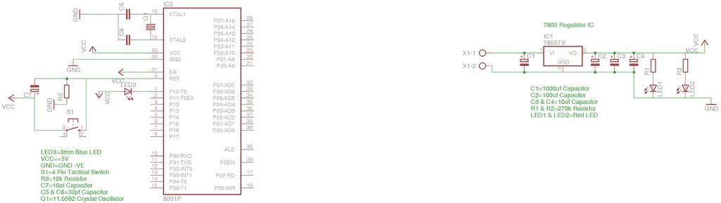
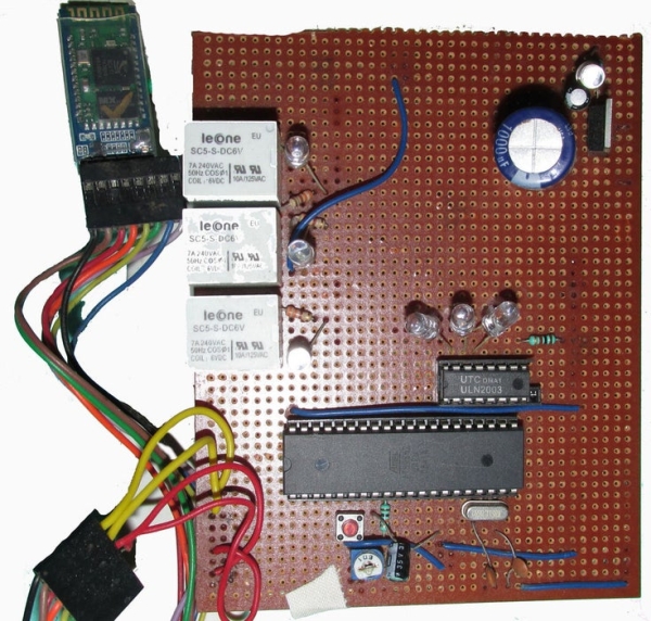
Resistances and capacitors as circuit diagram depicts(below)
power module(if the input is more than 5V or else not necessary)
IC 7805(5V voltage regulator)
1000uF capacitor
10uF capacitor
led and resistance(as per convenience so that led doesn’t get damaged)
IMPORTANT NOTE: USE 11.0592MHz crystal oscillator as this only gives a baud rate of 9600 same as bluetooth module. So to establish communication between microcontroller and HC-05 we need to match their baud rate just like “WALKIE-TALKIE frequency”)
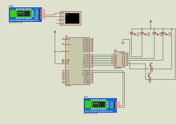
Step 2: CIRCUIT DESIGN
The circuit diagram is as given above. This circuit can be improvised like :-
the reset circuitry can be omitted if want to do reset through code.
The 5V power supply circuit can be omitted if you have a 5V standard source.
Relay of 6V can be used but the +ve pin should be connected through 6V supply.
Relay driver IC acts as a NOT gate i.e. when signal from microcontroller comes to it, the output of ULN2003 is 0V, initially it’s active high. More bits of microcontroller port i.e. P2 port’s bit(e.g. P2.0,P2.1,P2.2-P2.7) can be connected to remaining ULN2003 IC input pins thus respective output can be obtained.
Include P3 port with another UNL2003 IC.
After circuit design the main thing on which the circuit will operate is the CODE that says on which signal which port will be 1 or 0!!!
Step 3: CIRCUIT EXPLANATION
The basic is very simple…
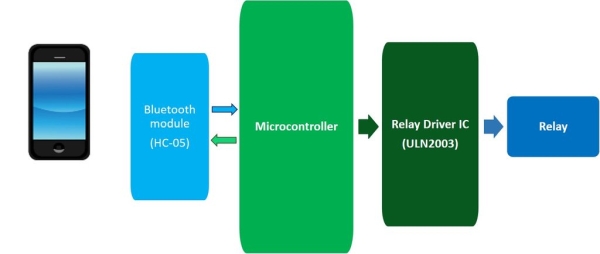
You need a bluetooth enable host device i.e. mobile,computer or anything!! For the sending of command to the circuit.
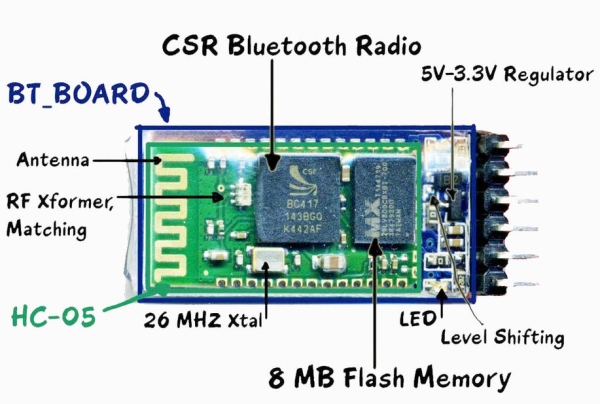
We have used a bluetooth module(HC-05 “HANDS & LEGS OF THE CIRCUIT” ) for catching the signal from paired host device and relaying the same to the microcontroller through its Tx pin to TxD of the later. But you can also use HC-06/07, Sable-x-R2, TIWI-uB1 etc.
Now comes the microcontroller…”HEART & BARIN OF THE CIRCUIT”… receives data from bluetooth module and does the work according to the code written in it and REPLIES to the bluetooth module.(TxD to Rx)
Pins of microcontroller gives output and thus connected pins of ULN2003 receives it and gives 0V(initially 5V) making the relay trip(work).
Relay’s one leg connected to 5V(OR 6V) and another leg get 5V or 0V depending on ULN2003 output. When potential difference(voltage) across relay is 6V it works for 0-3V it doesn’t work.
BE CALM & INNOVATE & MAKE CIRCUITS…
The next edition of this circuit is wifi enabled, IOTs working on it.
THANKS TO INSTRUCTABLES
Step 4: CODE
I have written the code in embedded C format in Keil uVision… for the code email me…(abhrodeepc07@gmail.com) I HAVE GIVEN THE PROTOTYPE OF THE CODE IN THE ABOVE PICTURE YOU CAN INNOVATE AND MAKE IT EITHER… WRITE PROGRAM>>SAVE IT IN “*FILENAME*.C” FORMAT>>BUILD>>GET HEX FILE>> AND UPLOAD…
Snapshots are self explanatory… The application name is “Custom Bluetooth App”, which can be downloaded from internet. This can be customized from setup button according to command and respective output through microcontroller. Used “SPP bluetooth” app in video reference(downloadable from google play store)
This is Tahir Ul Haq and introduces you to another member in the family.
This time the project is named as Weather Monitoring System. This is another TIVA based project presented by students of UET LHR.
Weather monitoring plays an important role in human life, so the collection of information about weather changes is very important. In any industry during certain hazards it is very important to monitor weather. In this project, we will monitor different weather parameters with the help of respective sensors. These sensors will be interfaced with TM4C1233H6PM microcontroller and there output will be shown on an LCD module. These temperature parameters include temperature, humidity and light intensity. Our system includes DHT 22 sensor for measuring temperature and humidity and a photodiode which is used to measure relative light intensity in the atmosphere.
Step 1: Introduction:
An automated weather system is a system that measures and records meteorological parameters using sensors without intervention of humans. The measured parameters can be stored in a built-in data logger or can be transmitted to a remote location via a communication link. If the data is stored in a data logger, recorded data must be physically downloaded to a computer at a later time for further processing. Therefore, the communication system is an essential element in an automated weather station. Today, automated weather stations are available as commercial products with variety of facilities and options. Although automated weather stations can be built and implemented in remote areas to bring down the cost of maintaining weather stations, until recently, not much emphasis has been given for building and using such instruments locally. Automated weather stations have been developed in universities by interfacing meteorological parameter monitoring sensors to microcomputer/commercially available data loggers with communication devices or through serial and parallel ports to obtain hard copies of weather data. We are going to design such a small embedded system which can be used locally to monitor weather.
Step 2: Methodology:
In this project, we are using DHT 22 digital humidity and temperature sensor to measure humidity and temperature. DHT 22 sends the 40 bit digital data to the microcontroller.
The microcontroller processes this data and shows the result on the LCD module. The light intensity is measured with the help of a photodiode. Photodiode, after sensing the light intensity, gives us an analogue voltage value. Microcontroller receives this analogue voltage value and does its ADC and finally converts its digital output to relative light intensity.
Step 3: Components:
Components Required are:
> Tiva micro-controller
> DHT-22 Sensor
> Photo diode
> 16*2 LCD module
A. Tiva Launchpad:
The Tiva Launchpad (TM4C123GH6PM) was used as the microcontroller in the project. The microcontroller has a 64 pin package. Out of these 64 pins, 43 pins are available for the purpose of GPIO pins. These GPIO pins are grouped into six ports labelled Port A to Port F. Port A to D are 8 pin ports, while port E is 6 pin and Port F is 5 pin. Each of the pins on these ports can be configured as GPIO. Some of the port pins also have special peripheral functionalities multiplexed along with GPIO functionality and can be configured for that purpose as well.
B. DHT 22 humidity and temperature sensor:
1. Features: DHT 22 is a Digital Humidity and Temperature sensor which gives a precise value of both temperature and humidity measurement. It utilizes exclusive digital-signal-collecting- technique and humidity sensing technology, assuring its reliability and stability. No extra components are required for its interfacing with the microcontroller. Small size & low consumption & long transmission distance (20m) enable DHT22 to be suited in all kinds of harsh application occasions. Single-row packaged with four pins, making the connection very convenient. Its humidity measurement range is 0 to 100% RH (Relative Humidity) and temperature range is -40 to 80 degree Celsius.
2. Power and Pins:Power’s voltage should be 3.3-6V DC. When power is supplied to sensor, don’t send any instruction to the sensor within one second to pass unstable status. One capacitor valued 100nF can be added between VDD and GND for wave filtering.
3. Communication and signal: Single-bus data is used for communication between MCU and DHT22, it costs 5mS for single time communication. Data is comprised of integral and decimal part, the following is the formula for data. DHT22 send out higher data bit firstly! DATA=8 bit integral RH data+8 bit decimal RH data+8 bit integral T data+8 bit decimal T data+8 bit check-sum If the data transmission is right, check-sum should be the last 8 bit of “8 bit integral RH data+8 bit decimal RH data+8 bit integral T data+8 bit decimal T data”. Figure 3. Serial data transfer between DHT 22 and Microcontroller. As shown in Figure 2, when MCU send start signal, DHT22 change from low-power- consumption-mode to running-mode. When MCU finishes sending the start signal, DHT22 will send response signal of 40-bit data that reflect the relative humidity and temperature information to MCU. Without start signal from MCU, DHT22 will not give response signal to MCU. One start signal for one time’s response data that reflect the relative humidity and temperature information from DHT22. DHT22 will change to low- power-consumption-mode when data collecting finish if it don’t receive start signal from MCU again.
C. Light Intensity Sensor (Photodiode):
Photodiode is designed to be responsive to optical input in such a way that when light falls on it, a reverse current flows through it due to the principle of photoelectric effect. As a result, a potential is developed across it. The reverse photoelectric current varies directly with the intensity of light.
Greater the current, greater will be the current and so the voltage. So, by measuring the voltage developed across the photodiode, we can calculate the intensity of light by multiplying the voltage by a suitable constant factor.
D. 16 × 2 LCD Display:
A liquid-crystal display (LCD) is a flat-panel display or other electronically modulated optical device that uses the light-modulating properties of liquid crystals. Liquid crystals do not emit light directly, instead using a backlight or reflector to produce images in color or monochrome.LCDs are used in a wide range of applications including computer monitors, televisions, instrument panels, aircraft cockpit displays, and indoor and outdoor signage. Small LCD screens are common in portable consumer devices such as digital cameras, watches, calculators, and mobile telephones, including smartphones. LCD screens are available in a wider range of screen sizes than CRT and plasma displays, with LCD screens available in sizes ranging from tiny digital watches to huge, big-screen television sets. 16×2 LCD is named so because it has 16 Columns and 2 Rows.
Step 4: Codes and Videos:
The codes have been implemented in Keil uvision4.
For details of various lines of codes you can refer to tiva launchpad datasheet at
The datasheets for the sensors and photo diodes have also been attached.
Step 5: Conclusion:
We designed a small embedded system which can monitor different weather parameters like humidity, temperature and light intensity. Respective sensors measure the corresponding weather parameters, microprocessor receives and processes this data and ultimately shows the resulting measurement on the LCD module.
VivoGame (something like “liveGame” in english) is a funny 2 players game whose goal is hit a target with a automated dart. One player wear a “glasses” that doesn’t let him see the target. 3 leds that replace each lens, allow the other one, who see the target, moving the first player’s head with a joystick (strange but very funny!). When, for instance, the joystick is moved to the left, a led is turned on in front of the left eye of the player with the glasses. Other leds allow moving up, down and to the right. Upon the glasses, there is a dart launcher automated through a servo motor. Pressing the joystick button, the player can trigger the servo and throw the dart.
Step 1: Assembling the Glasses
To assembly the glasses you’ll need: cardboard, paint, elastic cord, rubber bands, scissors, a servo motor, hot glue and a lot of creativity!
With the cardboard, the paint and the scissors, assemble and paint the body of the glasses (Tip: You can use a thin box and adapt it to fit the face). Use the elastic cord to hold the glasses on the head.
To assemble the dart launcher, paste the servo motor upon the glasses and use some rubber bands with the ends attached at the glasses’ body as a slingshot.
Step 2: Assembling the “lens”
To assemble the lens, you’ll need: 2 styrofoam blocks, 6 leds, 4 resistors (100 ohm) and a five-wires cable (we’ve used an UTP cable).
Attach the leds at the styrofoam blocks as in the illustration and assemble, with the leds and the resistors, the circuit shown in the schematic.
Attach each connector (G, L, U, D e R) at a wire of the cable.
Connect the wires from the leds to the Mezzanine as follow (CONNECTOR, MEZZANINE PORT):
(L,4); (R,7); (U,5); (D,6); (G, GND).
For the joystick, we’ve used this module. Connect it to the Mezzanine in this way (MODULE PIN, MEZZANINE PORT): (X, A0); (Y, A1); (GND, GND); (VCC, VCC).
At the Dragon board, launch the Arduino IDE, compile the code and download to the Mezzanine.
At now, we have a lot of idle fire power with the DragonBoard. We can use it to link the game to a web application.
In this wireless gesture controlled robot project I am going to control a robot using hand gestures. This is an easy, user-friendly way to interact with robotic systems and robots. An accelerometer is used to detect the tilting position of your hand, and a microcontroller gets different analogue values and generates command signals to control the robot. This concept can be implemented in a robotic arm used for welding or handling hazardous materials, such as in nuclear plants.
Step 1: Circuit Components
Semiconductors
IC1 – 7805, 5V regulator
IC2 – ATmega328 microcontroller
IC3 – LM1117-33, 3.3 voltage regulator
IC4 – HT12E, 2 12 series encoder
IC5 – HT12D, 2 12 series decoder
IC6 – L293D, dual H-bridge motor driver
LED1 & 4 – 5mm LED
Resistors (all 1/4-watt, ±5% carbon):
R1 – 1-mega-ohm
R2 – 10-kilo-ohm
R3 – 750-kilo-ohm
R4-R7 – 220-ohm
R8 – 47-kilo-ohm
Capacitors:
C1, C2 – 22pF ceramic disk
C3 – 0.1μF ceramic disk
C4 – 0.33μF ceramic disk
C5 – 10μF, 16V electrolytic
Miscellaneous:
CON1, CON3 – 2-pin connector
CON2 – 6-pin connector
X TAL 1 – 16MHz crystal
TX1 – 433MHz transmitter module
RX1 – 433MHz receiver module
M1, M2 – DC-geared motor, 100rpm
S1, S2 – On/off switch
Batt.1 – 9V PP3 battery
Batt.2 – 4.5V, 1.5Ah lead-acid battery
ANT.1, ANT.2 – 17cm long single-strand wire antenna
– ADXL335 3-axis accelerometer
Step 2: What Are Those?
ATmega328
ATmega328 is a single-chip microcontroller from Atmel and belongs to the mega AVR series. The Atmel 8-bit AVR RISC based microcontroller combines 32kB ISP flash memory with read-while-write capabilities, 1kB EEPROM, 2kB SRAM, 23 general-purpose I/O lines, 32 general-purpose working registers, three flexible timers/counters with compare modes, internal and external interrupts, serial programmable USART, a byte-oriented 2-wire serial interface, SPI serial port, 10-bit A/D converter, programmable watch-dog timer with an internal oscillator and five software-selectable power-saving modes.The device operates between 1.8 and 5.5 volts. It achieves through puts approaching one MIPS per MHz. An alternative to ATmega328 is ATmega328p.
ADXL335
This is a complete three-axis acceleration measurement system. ADXL335 has a minimum measurement range of ±3g. It contains a poly-silicon-surface micro-machined sensor and signal-conditioning circuitry to implement open-loop acceleration measurement architecture. Output signals are analogue voltages that are proportional to acceleration. The accelerometer can measure the static acceleration of gravity in tilt-sensing applications as well as dynamic acceleration resulting from motion, shock or vibration.
The sensor is a poly-silicon-surface micro-machined structure built on top of a silicon wafer. Poly-silicon springs suspend the structure over the surface of the wafer and provide resistance against acceleration forces. Deflection of the structure is measured using a differential capacitor that consists of independent fixed plates and plates attached to the moving mass.
Fixed plates are driven by 180° out-of-phase square waves. Acceleration deflects the moving mass and unbalances the differential capacitor, resulting in a sensor output whose amplitude is proportional to acceleration. Phase-sensitive demodulation techniques are then used to determine the magnitude and direction of the acceleration.
L293D
This is a 16-pin DIP package motor driver IC (IC6) having four input pins and four output pins. All four input pins are connected to output pins of the decoder IC (IC5) and the four output pins are connected to DC motors of the robot. Enable pins are used to enable input/output pins on both sides of IC6.
Encoder (HT12E) and decoder (HT12D) ICs
The 212 encoders are a series of CMOS LSIs for remote-control system applications. These are capable of encoding information that consists of N address bits and 12 N data bits. Each address/data input can be set to one of two logic states. Programmed addresses/data are transmitted together with header bits via an RF or infra-red transmission medium upon receipt of a trigger signal. The capability to select a TE trigger on HT12E or a data (DIN) trigger on HT12D decoder further enhances the application flexibility of 212 series of encoders. The HT12D also provides a 38kHz carrier for infra-red systems.
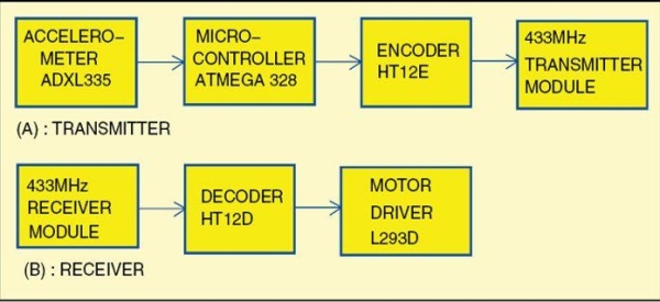
Transmitter
The transmitter consists of ATmega328 microcontroller (IC2), ADXL335 accelerometer, HT12E encoder (IC4) and 433MHz RF transmitter module (TX1). In this circuit, two analogue outputs from ADXL335 pins (x, y) are connected with input pins (23, 24) of the microcontroller. Analogue signals are converted to digital signals through the microcontroller. Digital outputs from pins 16, 17, 18 and 19 of the microcontroller are directly sent to pins 13, 12, 11 and 10 of encoder IC4. This data is encoded and transmitted via RF module TX1.
Receiver
The receiver part consists of 433MHz RF receiver module (RX1), HT12D decoder (IC5) and L293D motor driver (IC6) to run the motors. Here, receiver module RX1 receives the transmitted signal, which is decoded by decoder IC to get the same digital outputs. Four outputs of IC6 drive two motors. The robot moves as per tilt direction of the accelerometer in the transmitter.
Step 3: Block Diagram
Step 4: Transmitter and Receiver Circuit
Step 5: PCB Layout of Receiver and Transmitter Circuit
The first two images are the layout of receiver circuit and the other two images are the layout of transmitter circuit.
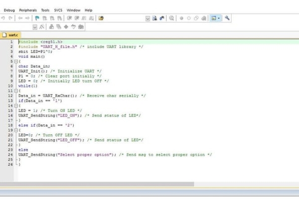
Step 6: Software Program
The software program is written in Arduino programming language. I programmed a fresh ATmega328 microcontroller with the help of Arduino IDE 1.0.5 and an Arduino Uno board.
First,you have to load bootloader code into the microcontroller. For that, I used Arduino Uno for in-system programming (ISP) given in the IDE, by selecting File → Examples → Arduino ISP. Once the bootloader is uploaded into the microcontroller, gesture.ino code of this project can be uploaded.
Step 7: Source Code
const int ap1 = A0;
const int ap2 = A1;
int sv1 = 0;
int ov1 = 0;
int sv2 = 0;
int ov2= 0;
void setup()
{ // initialize serial communications at 9600 bps:
Serial.begin(9600);
pinMode(13,OUTPUT);
pinMode(12,OUTPUT);
pinMode(11,OUTPUT);
pinMode(10,OUTPUT);
}
void loop()
{ analogReference(EXTERNAL); //connect 3.3v to AREF
// read the analog in value:
sv1 = analogRead(ap1);
ov1 = map(sv1, 0, 1023, 0, 255);
delay(2);
sv2 = analogRead(ap2);
ov2 = map(sv2, 0, 1023, 0, 255);
delay(2);
Serial.print(“Xsensor1 = ” );
Serial.print(sv1);
Serial.print(“\t output1 = “);
Serial.println(ov1);
Serial.print(“Ysensor2 = ” );
Serial.print(sv2);
Serial.print(“\t output2 = “);
Serial.println(ov2);
if(analogRead(ap1)<514 &&analogRead (ap2)<463) // for backward movement
{
digitalWrite(13,HIGH);
digitalWrite(12,LOW);
digitalWrite(11,HIGH);
digitalWrite(10,LOW);
}
else
{
if(analogRead(ap1)<486 &&analogRead (ap2)>508) // for left turn
{
digitalWrite(13,LOW);
digitalWrite(12,HIGH);
digitalWrite(11,HIGH);
digitalWrite(10,LOW);
} else
{
if(analogRead(ap1)>512 &&analogRead (ap2)>560) // for forward
{
digitalWrite(13,LOW);
digitalWrite(12,HIGH);
digitalWrite(11,LOW);
digitalWrite(10,HIGH);
}
else
{
if(analogRead(ap1)>550 &&analogRead (ap2)>512)//for right turn
{
digitalWrite(13,HIGH);
digitalWrite(12,LOW);
digitalWrite(11,LOW);
digitalWrite(10,HIGH);
}
else
{
digitalWrite(13,HIGH);
digitalWrite(12,HIGH);
digitalWrite(11,HIGH);
digitalWrite(10,HIGH);
Step 8: Testing
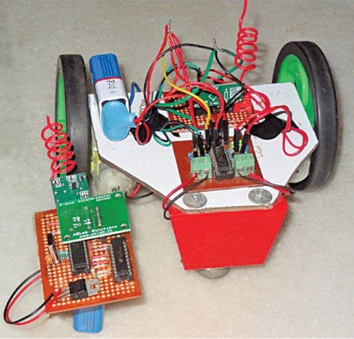
Mount all components on the PCBs shown here to minimise assembly errors. Fix the receiver PCB and 4.5V battery on the chassis of the robot. Fix two motors, along with wheels, at the rear side of the robot and a castor wheel on the front. After uploading the main code into the microcontroller, remove it from the Arduino Uno board and insert it into the populated transmitter PCB.
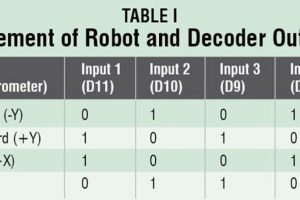
Now, switch-on the power supplies in the transmitter as well as receiver circuits. Attach the transmitter circuit to your hand(or to a gloves) and move your hand forwards, backwards and sideways. Directions of the robot movement are given in Table I. The robot will stop if you keep your palm horizontal, parallel to the Earth’s surface.
For troubleshooting, first verify that voltages at various test points are as per Table II.
Some time ago, I tried to make an “Instructables Hit Counter” using the Instructables API, and an Arduino Uno with a wired network shield. However, with the limited RAM of the Arduino Uno, I was unable to get the system to work.
A while ago, I noticed a similar project done by diytronics using a NodeMCU. This was just the right kick-off point to redo my project.
Using the ESP8266-01 WiFi module, I studied the various options available, and redesigned the system.
The first problem when using the ESP8266 modules, is setting up the unit to connect to an existing WiFi access point. I did not want to do this using code, as this required the code to be changed and reprogrammed into the ESP8266. I found the WiFiManager library very useful, and made use of the examples to get the easiest method to connect the EP8266 to a WiFi network.
Next, I did not want to make changes to the code each time I wanted to change the Instructable to be monitored. For this, I set up the ESP8266 with a build-in web server to allow for easy changing of parameters.
Step 1: The Design
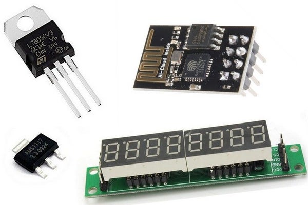
You will need the following components:
1 x ESP8266-01 Module
1 x max7219 8-digit 7 segment display
1 x 7805 Voltage regulator
1 x ASM1117 3.3V voltage regulator
Power Supply
The power for the unit is obtained from a 12V DC power supply. We will need two supplies:
5V for the max7219 display
3.3V for the ESP8266-01
Refer to the schematic diagram.
A diode is used to protect the unit from incorrect polarity connections, followed by the ON/OFF power switch. The input voltage is regulated to 5V by the 7805 voltage regulator. This 5V is used to power the max7219 display.
The 5V is also used to obtain the 3.3V needed by the ESP8266-01. The ASM1117 3.3 regulator is connected to the 5V regulator, and not to the DC input. This is to reduce heat that will be generated by the ASM1117 when connected to 12V supply. The ASM1117 3.3 used is a surface mount device, and can easily be soldered onto a piece of vero board.
AS the ESP8266 module can use up to 300mA when transmitting, each voltage rail is fitted with a decent sized smoothing capacitor. To eliminate HF noise, 0.1uf capacitors are also fitted to each voltage rail.
ESP8266-01
With limited I/O pins available, care should be taken to allow for the ESP8266 to boot up correctly. To get the ESP8266-01 module to boot up in the correct mode, the following must be done:
CH_PD must be HIGH
RST must be HIGH
GPIO must be pulled HIGH
GPIO2 must be pulled HIGH
This is done using 10K pull-up resistors. This will ensure correct boot-up of the ESP8266 module.
I/O Pins
My design needed 5 I/O pins for the following:
3 pins for the max7219 display
1 pin for the MODE/SETUP button
1 Pin for the buzzer
As the ESP8266 only have four I/O pins available, there is one I/O pin short. Therefor the buzzer and MODE/SETUP button is connected to a single I/O pin. Software will be used to control the INPUT/OUTPUT mode of this pin.
max7219 Display
The display needs three I/O pins, but with the ESP8266 only having 2 general purpose I/O pins, the Rx and TX pins will also be used. This means that no Serial Monitor is available during development. To control the display, GPIO1, Rx and TX pins are used.
Buzzer/Button
With only one I/O pin left (GPIO0), the buzzer and MODE/SETUP is connected to this pin, and by using multiplexing, the pin is used to read the button status as well as sound the buzzer.
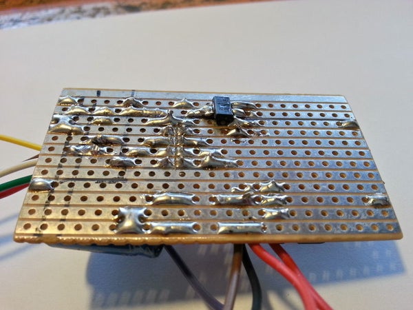
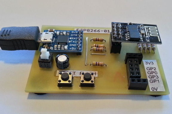
Step 2: Building the Circuit
With only a few components needed, the circuit was build on a small piece of vero board. The SMD ASM1117 regulator was soldered to the track side of the board.
To connect the ESP8266-01, I used 2 x 4-pin headers. This allows for easy remove of the ESP8266 module for programming. A sharp hobby knife was used to separate the vero board tracks between the ESP8266 pins.
Wires for the display, buzzer and button were soldered directly onto the vero board.
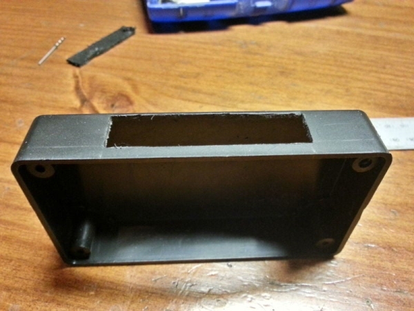
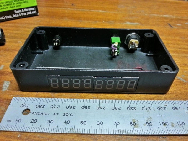
Step 3: Mounting the Display to the Enclosure
I had a small plastic enclosure available. To fit the display, I first make a cut-out for the display. The cut-out was made smaller than the display, and afterwards, filed to ensure the display fits snugly into the cut-out.
Using a permanent black marker, the white on the display was made black, and the display glued into position using epoxy.
Step 4: Mounting Other Items
The power jack, On/Off switch, button and buzzer was mounted to the back of the enclosure.
For the buzzer, I drilled a 3mm hole in the enclosure, and glued the buzzer over this hole. This ensures that the buzzer will be load enough.
With all components fitted, the wiring between the components were made using thin wire.
Step 5: Programming the ESP8266-01
Upload the code to the ESP8266-01 with your method. For ease of reference, I have included the libraries used.
Please note that I have modified the LedControl library, thus you will have to use my LedControlESP8266 library.
Step 6: Connecting to Your WiFi
For the Hit Counter to function correct, we first need to connect the unit to a WiFi access point. Follow these steps:
Power up the unit
When “Set Net” is displayed, press the MODE/SETUP button for about 2 seconds
The display will now show “no con”
Go to your PC or smartphone, and select the WiFi connections
Select “Instructables Hit Counter”
Open your internet browser. If the configuration page does not automatically open, type in the following IP address: 192.168.4.1
Click on Configure WiFi
Select the required WiFi access point, and enter the password for this access point
Next, enter the IP address, Gateway and Mask as per your requirements
Once done, click on the Save button
When successful, you will receive a confirmation message that the data has been saved.
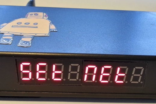
Once connected, the Hit Counter will display the current configured hits
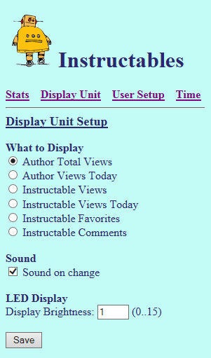
Step 7: Setup of the Hit Counter
Once connected, the settings of the Hit Counter can be changed using the unit’s web page.
Open your web browser, and enter the IP address of the Hit Counter.
Hit Counters
The unit can be set up for two type of Hit Counters. Each of the counters have to be set up individually.
Author Screen Name- Shows total number of hits for a specific author.
Instructables ID – Shows total number of hits for a specific Instructable hits. Refer to the bottom of the web page for more information on obtaining the ID
Display
The unit can be set to display either the Author or Instructable hits:
Select Author Total Hits to display total number of hits for the Author
Select Instructbles ID Hits to display total number of hits for the Instructable
Sound
Select this option if you want the unit to beep on changes to the displayed hit counter.
Display Brightness
The display brightness can be changed via the web page. Enter a brightness level between 0 .. 15 as per requirements.
Step 8: Using the Instructabes Hit Counter
Once connected, the unit does not have a lot of functionalities. Apart from the MODE button, there is no other interfacing between the unit and the user.
Pressing the MODE button will alter the display between the Author Total Hits and Instructable Hits.
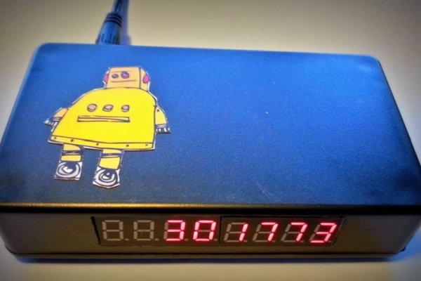
Note: updated with new firmware, a schematic and a tips for a programmer.
A couple of years I embarked on my own home automation project. It started off by building a server controlled 433 MHz transmitter build with an Arduino to switch lots of cheap PT2262 based remote switches. Later I added an Arduino based receiver for my weather station, hooked up the control contact of my EV charger, etcetera. Things grew more and more intertwined (and complicated!). So, a few months ago I decided to standardize everything based on MQTT for messaging, Node-RED for automation (both running on a single Raspberry Pi B+) and MariaDb for logging (running on my Synology NAS). Later I moved the MQTT broker (Mosquitto) and Node-RED over to the NAS too..
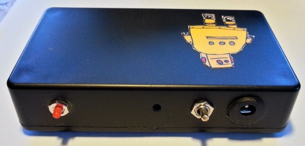
This instructable describes a silly for-fun project hooking my street mounted mailbox in this home infrastructure. The idea is that if somebody opens the fence mounted mailbox about 10 meters from the front door, it signals me on my phone and possibly other devices.
Step 1: Outline, Prerequisites and Parts
Outline
On a high level, the mailbox should, when opened, send a unique MQTT message to the broker, so that subscribers to that topic will be informed. Node-RED subscribes too and does some automation, in this case sending an email and/or a push message to my phone.
The mailbox should run on batteries and run for at least a year, and should do so using my WiFi network. As awakening a micro-controller and connecting to a WiFi network can take several seconds, I could not use the activation switch to cut the power. Instead, the processor should be allowed to finish it’s business after the lid of the mailbox has already closed.
Prerequistites
I assume your have modest soldering skills, have worked with the Arduino IDE a bit, and have installed the ESP8266 boards using the Boards Manager. You also need to have a 3.3 volt USB <> Serial adapter to program the micro-controller.
I also assume you have an MQTT broker and a Node-RED server running. If not, there are many instruction on the Internet, but I would advise to take the lazy route and use Peter Scargill‘s excellent install script if you want to run this on any Pi or Ubuntu, or use Andreas Spiess’s image for the Pi Zero W (links in the description of that video), which will save you a few hours of watching installation scripts running. Alternatively, you can make the firmware send out an email directly, but you will loose a lot of flexibility doing so.
Parts
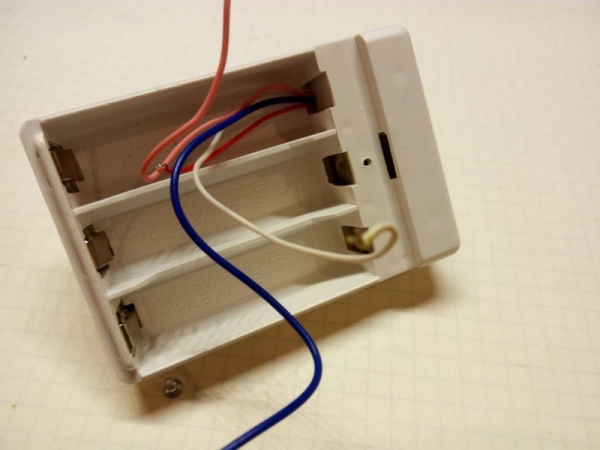
1 closed, 3 AA battery box
2 AA batteries
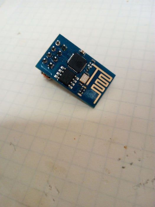
1 ESP8266 module. For this project I used an ESP-01
1 micro-switch
1 47K resistor
1 4M7 resistor
1 2.2uF capacitor
1 thin plastic tube. I used a pen
1 thick, long match or lollipop stick. It should easily fit and move in the plastic tube
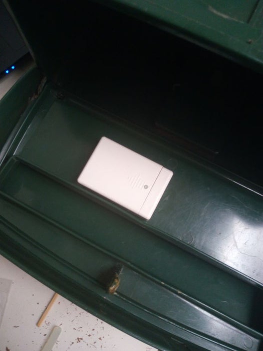
Step 2: Hardware: the Box, Switch and Wiring
I started with an old battery box from a defunct Christmas decoration. It was designed for three AA sized batteries. As the ESP8266 will run nicely on 3 volt, I could use two batteries and use the third position for the micro-controller. Notice how the box had a small extra compartment that I could use for the activation switch. I used a very common type of switch shown in the pictures, but removed the spring that latches it in the on or off position. I soldered two thin wires to the NC contacts and glued it in the box with a tiny drop of super glue.
Next, I drilled a hole in the top cover matching a plastic tube taken from a ball pen. The hole lines up exactly with the switch and guides a plunger made from a thick match stick.
Finally, I soldered two more wires to the battery contacts and guided all four wires to the position of the third battery, where the micro-controller was going to be.
Step 3: Hardware: the ESP-01
Given the WiFi requirement, the entire project shouts ESP8266. This small WiFi controller has become the favorite workhorse of the tinkering community as a module that an be bought under EUR 2.50 and integrates a full WiFi and TCP/IP stack, with more than enough capacity to spare to run your own programs. The Arduino IDE (or Atom with the PlatformIO plugin) fully supports the ESP8266.
I would usually take an ESP-12F, but I had a tiny ESP-01 board laying around that was perfect for the job and fits nicely in the battery box. The only problem is that is is quite complicated to flash firmware in the ESP-01. More on that in the next step. There is one modification to make: You have to remove the red power LED from the board, as it continuously draws 3mA. With the LED removed, the module uses just a few tens of uA in deepsleep mode which will make it last for over a year on two quality AA batteries.
It turned out that I could use two strips of 4 pin female headers and solder on the few extra components in free form so that I could remove the ESP-01 to update the firmware, while it would still fit in the third battery compartment.
It is very important to correctly wire the ESP. Using the above cheat sheet, wire it up as follows.
Battery plus to Vcc (D2), CH_PD (B2), RXD (D1), GPIO0 (C1), GPIO2 (B1) and a 47K resistor.
Battery minus to GND (A1) and one wire of the switch.
The other wire of the switch to a 100nF capacitor and a 4M7 resistor.
The open ends of both resistors and the capacitor to RST (C2).
TXD (A2) can remain unconnected.
Edit: I had to replace the ESP-01 because I made a silly mistake and destroyed it. Turned out that to my surprise the new ESP-01 did not reset with the original 100nF capacitor. It probably has a slightly different design. I replaced it with a 2.2 uF one and now it works again.
When done, everything can be mounted in the box, but hold on, first we need to program the module.
Step 4: Programming the ESP-01
To flash the firmware on your ESP-01, you can either build a small rig or buy an (almost) complete programmer for about 1 euro.
Programming hardware rig
Build a small rig with again two female headers for the ESP-01. Also, you need a USB <> Serial module, capable of providing 3.3 volt. Note that the ESP8266 chip is not 5 volt hardened, so a mistake here could kill your module. Anyway, again using the cheat sheet, wire your rig as follows:
3.3V from the USB<>Serial module to Vcc, CH_PD, RST and GPIO2.
GND of the USB<>Serial module to GND and GPIO0.
TXD of the USB<>Serial module to RXD.
RDX of the USB<>Serial module to TXD.
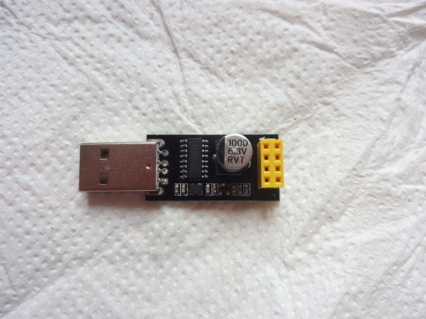
Pre-build programmer
Fun as it is to build your own stuff, the lazier approach is to get a ESP-01-to-serial interface from your favorite auction site, see the picture above. This is much easier, more compact and more reliable than a rig. However, some of these are not programmers, just serial interfaces. You need to solder a wire bridge between GND (pin A1) and GPIO0 (pin C1) on the backside of the interface, see the second picture. Note that the ESP-01 should be plugged in with the antenna facing the USB plug, not the other way around!
Note: they also exist with a switch, see third picture, very nice.
Load the firmware
Assuming an Arduino IDE of 1.8.3 or later, select Tools > Board and select the board you have. For an ESP-01 like I used, choose “Generic ESP8266 Module”, and set the following options (this should be all the defaults):
Flash Mode: DIO
Flash Frequency: 40MHz
CPU Frequency: 80MHz
Flash size: 512KB (64KB SPIFFS) Note: if you use a black ESP-01 board, choose 1MB (64KB SPIFFS)
Debug port: Disabled
Debug level: None
Reset method: ck
Upload speed 115200
Port: select the port that is connected to your USB <> Serial interface. For my Ubuntu PC that was /dev/ttyUSB0
Hook up the rig / programmer, load the Sketch you can find here https://gitlab.com/jeroenmeijer/Mailbox.git. Supply your WiFi and MQTT broker credentials and your IP configuration in config.h and choose Upload.
Step 5: Assembling It All
I drilled a hole for the plastic tube in the inner lid of my mailbox, as close to the hinge as possible, then hot-glued the battery box to the underside of that lid. Next I used a thick match as a plunger. I used a snip to cut the match to length so that the switch would open if the outer lid was closed. I checked connectivity by opening the lid while running mosquitto_sub to monitor MQTT messages (replace mqttbroker, user and password with your MQTT configuration):
Approximately six second after the outer lid is opened the following MQTT message is published. The time is used to wake up the micro-controller and establish the WiFi and broker connection.
During this time, the micro-controller used approximately 70mA. When done, it goes into deep sleep and in my case it used less than 20uA. “flap” is always true, “vcc” states the battery voltage in mV and “prev” should be 0. If it is 1 or 2, it means the mailbox was unable to send a message earlier, either because it could not connect to the WiFi, or because it could not connect to the MQTT broker. “RSSI” is the strength of the WiFi signal. Both are very handy to diagnose problems.
It’s a good idea to monitor the battery voltage for a few days to ensure the device works as intended and doesn’t drain it’s battery for some reason.
The firmware is also able to update itself over the air (OTA), but that is a bit beyond the scope of this instructable. For those interested, the OTA configuration is also in config.h.
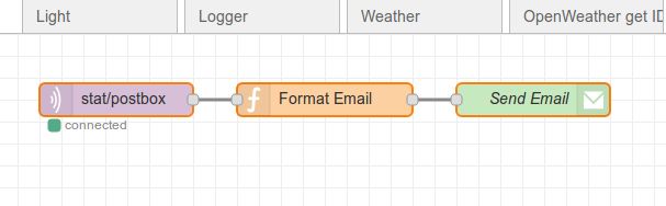
Step 6: Using Node-RED to Act on the MQTT Message
Finally, I created a simple flow in Node-RED. The first node subscribes to the topic of the mailbox (stat/postbox/trigger). When a message is received, the second node formats an email *). The final node sends it out to my gmail address, using gmail as SMTP server. My phone will then alert me of new mail.
I have added the Node-RED flow to a gitlab snippet so you can import it into your Node-RED flows.
Of course you can add some more nodes, for instance to log the mailbox events to MariaDb or SqlLite, or create extra alarms when the battery voltage goes below 2.7 volts.
Happy mail-hunting!
*) See next page, I am using PushBullet now instead of email.
Step 7: After-thoughts
There is always this feeling things could have been done better.
Switch
I would have preferred to use a (super) magnet and a reed contact instead of the somewhat clumsy plunger approach. There were two reasons. One is, there was no way I could make this work with the contact closing when the box was opened, and having it always closed meant a small current would always be flowing. In retrospect, the less than 1uA flowing through the 4M7 resistor would not have been a big deal in terms of battery life. The other was a more practical one. I made up this project on Saturday and wrote the software, build it all on Sunday from what was laying around. I simply didn’t have a reed contact in the junk box.
Note: as diy_bloke commented, reed contacts have a tendency to get sticky when magnetized for a long time, so maybe the plunger was not such a bad idea at all. We will see. *)
Message on emptying
The mailbox sends out a message when emptying it too. This is no big deal but with more people in the house getting the warning, one might end up in a loop checking the mailbox defying it’s entire purpose! There are a few ways around this, such as checking if the inner lid is lifted, and if so, do not send a message. Or instead of using the lid switch, install a detector at the bottom of the mailbox. Or a small reset button to be pressed when emptying it. However, all would complicate things and probably worsen reliability.
Messaging
Sending email is a rather effective but crude way of putting out the warning. A more elegant way would be a phone app, but I have not found an Android MQTT dashboard app that can be configured to trigger an operating system alert when a certain message is received. If there is one around, please add to the comments. **)
*) After more than a year in operation, it turns out the lollipop stick I used, basically hard rolled paper, has a tendency to shorten under the constant pressure of the switch spring. After some troubleshooting I replaced it with a wooden stick.
**) I am using PushBullet now for push messages, separate from the MQTT dashboard. A tiny Node-RED low interfaces to the API can be found here. Make sure you supply the access token in node “Prepare for pushbullet” and your email address for fallback purposes in node “Retry”.
A DIY ATTiny44 based guitar preamp+effector. All the audio processing is done digitally on-board. So it is definitely not a HiFi system, but something you can definitely have fun programming. You can program the audio properties in Arduino IDE and create mobile apps that talk to the module for remotely controlling the effects.
This instructable project requires a milling machine to create the circuit as well as SMD components, but if anyone is looking for a more accessible option, please check out this Arduino based version: https://www.instructables.com/id/Arduino-Guitar-Ef…
Step 1: The Circuit: Preparation
The circuit for the effector will be made using a CNC milling machine. I used a Modela but anything similar will work. The list of material required will include:
LM386 (I used a DIP chip but SMD will make it more compact, while the traces need to be changed)
ATTiny44
4 x 10k resistors
1 x 1k resistor
1 x 255k resistor
1 x 5 ohm resistor
1 x 0.1 uF capacitor
1 x 2.2 uF capacitor
2 x voltage regulator
1 x 6-by-1 male connector
1 x 3-by-2 male connector
2 x 2-by-1 male connectors
2 x 3-by-1 male connectors
1 x 3-by-2 female connector
1 x 20 MHz crystal
There is redundancy in the schematics since I designed it for many other purposes. FTDI connection (6-by-1) is not very necessary since only two pins we need are Rx and Tx. If an SMD version of LM386 is used, the 3-by-2 female connectors are not necessary.
Components needed outside the circuit board are:
9V battery connector
10k potentiometer (a big one with a knob)
220 uF capacitor
1/4″ male audio connector
1/4″ female audio jack
1/8″ female audio jack
Sparkfun Bluetooth Silver Mate
Step 2: The Circuit: Making the Circuit
I used the png file above for routing the board. Depending on your setup, you will need to convert the file to machine code accordingly (eagle project for further modification is attached as well). In the png file, the outer border is through-cut, and the traces inside are only to remove the copper layer.
Note that there are two boards in the png file. The one in the left is the main circuit board with the microcontroller, where the one on the right is to have a separate voltage regulator for the Bluetooth module. It helps with reducing noise.
Once the circuit is completed, it is soldering time. The components placement can be found in the schematic (png or eagle) and in the picture above.
Step 3: The Circuit: Add Other Components
The final step for the circuit is to add audio connectors, a volume knob (potentiometer), a battery, and the Bluetooth module. The connections are illustrated above in the picture. I used female to female jumpers for the connection, but soldering cables directly to the circuit board (without connector pints) will make it more compact.
Note: I also added a capacitor between the knob potentiometer input and ground pins, and a potentiometer at the input stage for controlling volume. These are up to experiment and preference.
Step 4: Programming the Board
Download the arduino code and upload to your ATTiny44. Detailed instruction on how to program ATTiny can be found here if needed: http://highlowtech.org/?p=1695
Step 5: Printing the Case
Two parts of the case slide and snap into each other. Very sturdy, and no hinges are needed. The STL files for the casing are attached below.
Step 6: Assembly
Now finally the time to put everything together. All components connected to the circuit board are either mounted or enclosed by the 3D printed case. The volume knob and three audio connectors are mounted, and the battery, the circuit board, and the Bluetooth module will be placed in inside compartments like the picture above.
Step 7: Done!
Now it’s time to play! Here are some more samples. To use the effector, plug in the effector to your electric guitar and a pair of headphones to the 1/4″ jack, and start playing. I built a simple openframeworks app that sends numbers to the effector so I can switch between presets. It simply makes a serial connection with the effector and sends a single integer.