Once you’re getting familiar with your micro:bit, there’s a whole world of possibilities opening up, but there are some errors you might run into.
Here’s how to make two (or more) micro:bit communicate, even if the code is written on different computers.
Step 1: You’ll Need…
For this project, you’ll need two or more micro:bit. Meet up with a friend to share the fun!
It’s also practical to have a couple of battery packs, but not necessary if you’re able to power them in an other fashion.
Step 2: Making the Code in JavaScript Blocks Editor
Enter the webpage http://microbit.org/ choose “Let’s code” and JavaScript Blocks Editor.
Step 3: Decide Your Radio Group
If you’re uploading the same code from the same machine, the two micro:bit will probably manage to communicate. However, if you’re working with a friend or want to make sure they check the same channel, set your radio group at the same number.
Under Radio, you’ll find a block called radio set group. You can choose any number between 0 and 255, just make sure you use the same one.
Step 4: The Blue Code
To make the micro:bit talk, they can send and receive messages, which they then will translate into what you want them to do.
I have three micro:bit, so firstly I have Blue send a message to Yellow. This means that the three micro:bit will need to have different programming.
When I shake Blue, it will send the number 1.
You will find on shake under Input.
radio send number is under Radio.
In addition, I want to toggle showing the number 1, so that I know that the message is sent.This is to help if there are any errors at a later point.
I save the code as Blue and upload this code to the blue micro:bit.
Test the code by shaking the micro:bit. The number 1 should appear and vanish again.
Step 5: The Yellow Code
Start a new project.
Remember to set the radio group to the same number as the blue code.
Use the option on radio receivedNumber.
Set the number the yellow should receive to 1, since that is what blue is sending.
Yellow can then show 2 when it receive this message and send the number 2.
Notice that I place the pause and clear screen after sending the next message, to avoid breaks in the wrong places.
Save as yellow, upload to the next micro:bit. Make sure both micro:bit have power and test the code.
When you shake Blue, Yellow should show the number 2.
Step 6: The Pink Code
Start a new project, I’ll call mine Pink.
I mainly use the same blocks, though this time I’ll send a string instead of a number.
Upload to the pink micro:bit and test the code by shaking the blue one.
Step 7: Back to Blue
You probably noticed that Pink is sending “heart”, but no one is listening for that.
Let’s go back to Blue and add a line of code, so it will answer.
Remember to use the exact same word, spelling and upper/lower case letters, otherwise the micro:bit will not understand what the it is supposed to do.
Upload the new blue code and test.
Step 8: Running Too Many Times?
What I noticed at this stage, is that the micro:bit takes a long time before they reset. Instead, they keep sending the signals.
To prevent this, I added and changed some code.
Blue code:
After Blue has received the heart, it will send a 0 and clear the screen.
Yellow code:
I changed the on radio received back to receivedNumber and added a test.
You can find the new blocks under Logic:
If/else
Equal to
Variables:
receivedNumber
The code will now check which number is received. If the number is 1, it will run the code we made earlier.
If the number is anything other than 1, it will simply clear the screen.
Pink code:
Same as with the Yellow, expect it checks if the number is 2.
Please note that when Yellow receives 2 or Pink receives, this will also trigger the clear screen, as well as if they receive 0.
Step 9: No Limits!
This is how the radio works on the micro:bit. Hopefully this will give you plenty of ideas on how to use them together, maybe as a remote control, or a multiplayer game?
Keep an eye on your beloved bbies and play music or tell ’em to be quiet while you are away! This tutorial will show how to use a Raspberry Pi computer to monitor the volume of sound in your home (via the Cloud) to see if and when your pet is upset.
Drum roll… the most fun part: If it gets too loud (like Fido is barking or making some other raucous), we’ll you can tell them to be quiet or play music!
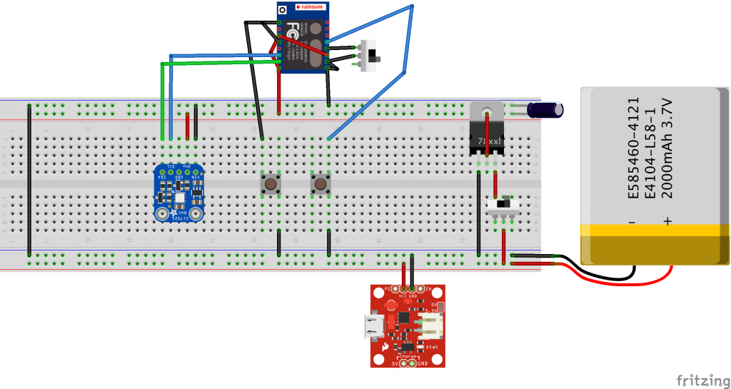
Along with the Pi (and speakers), we’ll use the SparkFun MEMS microphone breakout board to measure volume levels and trigger the audio player. Data is uploaded to the CloudMQTT service using the MQTT communication protocol.
To build this project, you’ll need a fully configured, WiFi-connected Raspberry Pi 3 computer with Raspbian OS. It’s also helpful to know some Python programming as well as the following things: (1) how to use and control the Raspberry Pi GPIO pins; (2) MQTT communication; and (3) analog sensors. If any of this is unfamiliar, or if you’re just curious (be curious!), check out the tutorials below!
MQTT (Message Query Telemetry Transport) is a popular IoT communication protocol. We’ll use the Paho Client Python library and an MQTT service called CloudMQTT. Here’s more about MQTT and how to use it:
The MEMS microphone is an analog microphone, so we’ll need an Analog-to-Digital converter (“ADC”) to read in the analog signal with the Raspberry Pi digital GPIO pins.
The OMXPlayer is an audio and video player pre-loaded on Raspbian OS. It works with most sound file types, including: .wav, .mp3, and .m4a. This is what we’ll use to play back sounds when Fido gets too loud. The Python library to control the OMXPlayer is included in Raspbian (woo!).
To test the OMXPlayer from the terminal, type the following:
omxplayer /home/.../SongFilePath/SongFileName.mp3
If that doesn’t work, try forcing it over the local audio-out device:
omxplayer -o local /home/.../SongFilePath/SongFileName.mp3
Step 4: Configure CloudMQTT Server
Now we set up an MQTT server! To do this using CloudMQTT, do the following:
You can monitor published messages in the “Websocket” UI.
Finally, install the MQTT Paho Client Python library:
pip install paho-mqtt
Step 4: Build It! Hardware
Pinout diagrams for the Raspberry Pi and the MCP3002 are in the photos above.
1. Insert MCP3002 pins into breadboard (see pinout diagram above)
The MCP3002 uses 4 SPI pins for communication: Serial Clock (“SCL”), Master Input Slave Output (“MISO”), Master Output Slave Input (“MOSI”), and Chip Select (“CS”). These pins correspond to Raspberry Pi GPIO pin 11 (SCLK), GPIO pin 9 (MISO), GPIO Pin 10 (MOSI), and GPIO Pin 8 (CE0).
Make the following connections with MCP3002 pins:
Connect Pin 1 to Raspberry Pi GPIO Pin 8 (CE0)
Connect Pin 2 to the analog output of the MEMS Microphone breakout board
Connect Pin 4 to GND
Connect Pin 5 to Raspberry Pi GPIO Pin 10 (MOSI)
Connect Pin 6 to Raspberry Pi GPIO pin 9 (MISO)
Connect Pin 7 to Raspberry Pi GPIO Pin 11 (SCLK)
Connect Pin 8 to Raspberry Pi 3.3V out
2. Solder wires to the MEMS Microphone breakout board. Connect to MCP3002 and Raspberry Pi.
Connect Vcc to Raspberry Pi 3.3V.
Connect GND to Raspberry Pi GND
Connect AUD to MCP3002 Pin 2
3. Plug in all the cables for the Raspberry Pi and turn everything on.
Step 5: Build It! Software
Our goal with the Bark Back is twofold: trigger a playback sound when the dog barks, and send the data to a server where we can check it.
Here’s the open-source Python program for this project.Feel free to (and please do) adjust and modify the code.
To get the program up and running, you need to fill in two things:
– songList: Write in the file path and file name for each of the songs you want to play.
– creds: Input your CloudMQTT information in this dictionary.
Step 1: Read in the SparkFun MEMS Microphone breakout board.
Read in the ADC value (between 0 and 1023) from the MEMS Microphone breakout board (via the MCP3002) using the SPI library and calculate the signal peak-to-peak amplitude.
Map the signal peak-to-peak amplitude to a Volume Unit. The current code maps the ADC range between 0 and 700 (based on quick experimentation) to a Volume Unit between 0 and 10. To adjust the sensitivity of the microphone, adjust the ADC input range.
First we’ll need songs to play! You can quickly record sounds in GarageBand (or on your smartphone) and send ’em to the Raspberry Pi. In Python, use the subprocess library to call the omxplayer.
In the code, input the file path of the songs you want to play back in the *songList* variable (line 26). The current volume threshold is set to 7 in the main function.
Step 3: Send data to CloudMQTT Server
Use the Paho Client Python library to communicate with the CloudMQTT servers. To broadly summarize: Set up a Client server; define communication protocols; connect with our credentials (aka creds); and subscribe and publish our data. Most of this is done in the main function (lines 129 – 149, and lines 169 – 174).
To check on received data, go to the “Websocket UI” tab in the CloudMQTT console.
Step 6: Test & Install!
Run the BarkBack.py program in Terminal or in the Python IDE (you can also use SSH to run the program after you’ve already left).
Check that you are getting volume levels in your Websocket UI tab.
Test the system by triggering the mic (clap, yell, bark, etc.) to be sure that the speakers play through all of the sounds.
Once everything is up and running, it’s recommended to solder the components to a PCB (Printed Circuit Board) if you intend to install the system for more than just a few days.
Last year 2016 I altered my garden and planted some new stock. Half way through the growing season I noticed that the right hand Carnation had grown far more vigorously than its twin only 20” away. The only differences to the plants was that a solar powered battery light had been placed by chance to shine directly down on the right hand plant.
I’m not sure why the three low powered LED’s would have made such a marked difference but I am going to try and see if I can create the same effect in my failing greenhouse.
As I am powering this project with a solar powered 7ah battery I want to make sure that I am not wasting power so I have created three light “zones”.
Sunshine , its pointless using light’s during direct sunshine, lights off.
Night time, I don’t want too attract unwanted two legged visitors so, lights sleeping.
Low light, times of low light dawn till dusk etc, lights on.
Sunshine and Low light are fairly straight forward on/off software controls, but Night time is a little different, I will show why in the software.
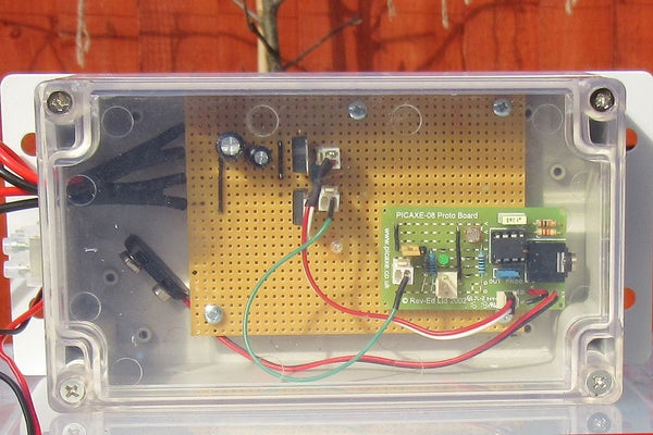
As I require the same sensor to control these zones I have used a Picaxe 8m2 micro controller and 8m2 project board to do the work. The circuits I have made are fairly straightforward and I have included circuit diagrams, I’m not an expert in circuit drawing but I think its all pretty straightforward.
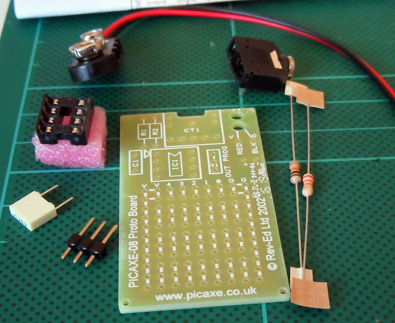
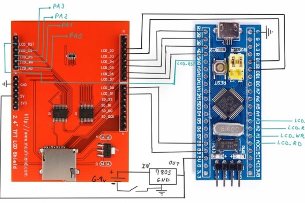
Step 1: Picaxe Circuit
The Picaxe project board kit is reasonably cheap and for simple circuits is adequate. I will describe the circuit by using the pin designations.
CO.0 is the serial output and it joins the 5v and 0v supply at the 3 pin connector. I use this connector to display the sensor value and unit conditions on a LCD unit.
CO.1 is the impulse line that controls the mosfet. It only needs a single line but I’ve used a double connector as it was all I had.
CO.2 is a LED indicator used to indicate that the unit is in test mode.
CO.3 this line is used to set pin 3 high when a jumper is connected across, this puts the software into test mode. The 10k resistor is used to pull down the line when the jumper is removed.
CO.4 a light dependant resistor and the 1k resistor form a voltage divider at pin 4 the pic then converts this analogue voltage to a digital number.
I have used the supplied battery cable so I can use battery power if I remove the Picaxe from the main board but I will be using the regulated 5v from the power circuit board via the 2 pin connector normally.
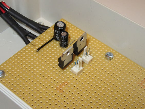
Step 2: Power
I’ve made a “normal” type of voltage regulator plus Mosfet circuit and all the information is on the diagram.
Pic+ and neg is the power connector for the Picaxe
C1 is the impulse line from CO.1 and the 10k resistor is the pull down for this line, again I had to use a double connector but its a single wire.
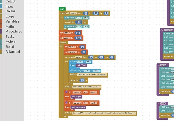
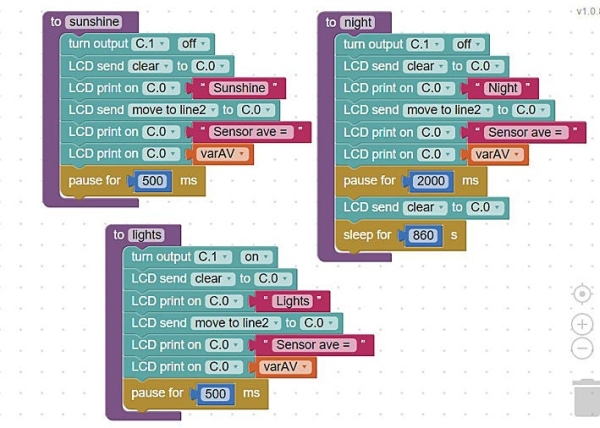
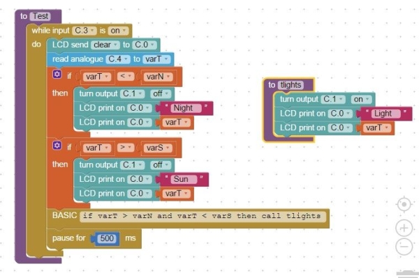
Step 3: Software Main Loop
I’ve written the software using Blocky a facility in the Picaxe Editor software plus some basic inserts. The main part is contained in a loop but first every good Picaxe program should start with a blinking LED and that is created with a 12 step for next loop (that sequence is not a part of the main loop).
VarN (night) and varS (sunshine) are then given their set points i.e. an average sensor reading below 50 will call the night procedure.
VarV and varAV are set to zero
A for next 12 step loop is next.
With each step C.3 is checked to see if it set on (on would call the test procedure.)
The analogue value is taken from C.4 and placed as a digital number into varB.
VarB is then added to varV.
The program then sleeps for 10 seconds. A second in this particular Picaxe is actually 2.1 seconds long so sleep 5 = 10 / 2.1 then rounded up.
After the 12 steps and around 120 seconds have passed varV is divided by 12 and the resulting average is placed in varAV.
The average varAV is then compared to 3 statements and the relative procedure is called
Step 4: Software Procedures
Sunshine and Lights procedures are very similar. These procedures turn C.1 either on or off and print a message on a LCD if fitted then return to the main loop.
Night is also simular to the previous two the main difference being that the program sleeps for 30 minute periods during the night to save power.
Step 5: Test Procedure and Set Up
To get a readout from the unit I use a simple LCD supplied in kit form from the Picaxe Store but to get the initial setting the unit can be connected with the download cable and the analogue sensor facility in the Picaxe Editor will give a real time reading from the sensor.
To get the high and low cut of points (varN and varS) to initially set the unit the jumper is used and C.3 goes high then a note is taken of the sensor value, i.e. when the natural light level has dropped or risen to the point were I want the unit to switch off I take a note of the sensor value from the test screen then update the program with that setting.
During the test procedure shading the LDR or illuminating it will cause the lights to turn on and off so that I can actually see that the unit is working.
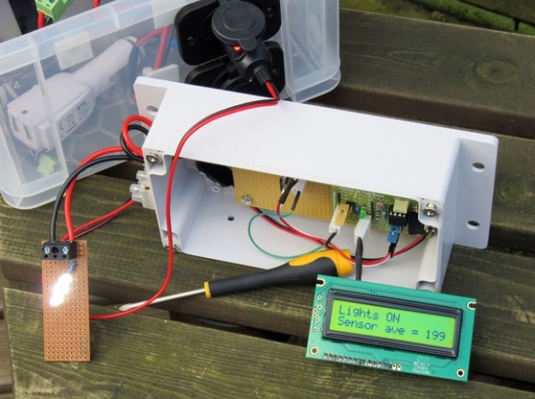
Step 6: Complete
The unit works as planned in the R&D dept and it is now ready for fitting in the greenhouse for its trial run.
I don’t imagine I will get it right first time so I think my Research and Development Dept (my wife calls it the back bedroom) could be busy over the coming weeks.
I also hope that people can understand my steps and diagrams and if not I’m always open to questions .
More patents for bicycle improvements have been issued than for any other machine. It is no wonder that the simplest of mechanical devices invites constant tinkering. If you do a search for speedometers for bikes you can come up with the old style mechanical contrivance with a gear driving a cable into a solid style housing that can still be bought on the web. While I have no great love for “retro” git I do like Analog as output rather than a number and my brain seems to like it better too. The instant picture of a state of being rather than the awkward pause of your brain circuitry going through translation hoops to get to a picture of time or speed. Anyway its rather neat to cruise down the street with a wizzy needle pointing out your lack of speed or short ride.
Using GPS is nice because it makes it self contained with no umbilical cord to the wheel. Its a little slow off the start –a second or two and it takes a minute or so to get its bearings right but if you are really OCD and must have a downloaded file of every inch that you traveled having a goofy dial on your bike is probably not for you. But for those who take some joy in the ride and want to fun-up their commute with their very own customized dial this may be a good project.
Step 1: Grab Some Hardware
The Hardware is pretty simple. All of it can be ordered from Adafruit. You use one of their new Feather boards with a GPS Feather attached directly above it. The battery is a 500 mAh unit that provides about 6 hours of use in my testing. But you can fit whatever you want in the case. The Feather is nice because it has built in charging so when you take it off your bike you can flip it on the charger overnight. This is not something that your going to leave on your bike anyway–its too attractive. The stepper motor is one normally sourced for speedometers in cars and Adafruit has a nice one for reasonable cost with a needle but you can get piles of these for cheap on the web. The motor driver is necessary because GPS and steppers don’t play nicely together on these small computers. The plastic cases I ordered on the web work well for a solid weather tight enclosure but you can also just carve a stackable grouping out of raw plexiglass.
1. Adafruit Feather 32u4 Basic Proto
2. Adafruit Ultimate GPS FeatherWing
3. Lithium Ion Polymer Battery – 3.7v 500mAh
4. Breadboard-friendly SPDT Slide Switch
5. Adafruit TB6612 1.2A DC/Stepper Motor Driver Breakout Board
6. Automotive Gauge Stepper Motor – x27.168
7. Break-Resistant Plastic Drawer Organizers 3″ x 3″ x 2″ l Set of 12
8. Adafruit LED Sequins – Ruby Red, Green
Step 2: Wire It Up…
The usual–use a breadboard. Follow the instructions on the Adafruit web site for stacking the GPS Feather with the main protoboard and soldering the connections as noted. The hardware serial connects the TX of the GPS feather with the RX of the main Feather board and the RX of the GPS to the TX of the main board. These plus ground and power are the only connections this board needs with its mating partner. Its a wonderful idea to check that the GPS data and the main board are working correctly and transmitting parsed data so use the demos on the Adafruit web page to make sure these guys are up and running. Once you have seen the miracle of data streaming from these units–something we now take for granted–wire up the motor shield and the stepper motor and test it with the motor shield demo tutorial just to make sure its working. I wired the stepper motor with the lipo-battery output fully expecting it not to work and thinking I would need a voltage booster, but it works fine surprisingly. Be very careful of the tiny solder pins on the stepper motor–they are really fragile and break off just where they come out of the case so as soon as you solder them to wires add some hot glue to the wire to stop any tension from torquing the connections. The switch in the diagram is for On/Off of the unit and the LED sequins are for various software defined uses.
Step 3: Enclose It
I built several different enclosures for the speedometer. The first was just a series of stacked cut plexiglass sheets with nylon spacers. The components were held on to the plates with double sided clear tape. It worked well for Maui where it doesn’t rain much but for Alaska I needed a more substantial plexiglass box. The components were held on to a carefully seated plate that mated nicely with the constriction 2/3 into the box providing a protected area for the needle to move in. Make sure you create an opening for the charging/programming cable to the computer. The GPS unit should be positioned so it has a good view of the sky.
Step 4: Your Dial
The stepper is not really a stepper but goes around 300 degrees. There are 600 steps in this range and you have to design your dial accordingly. The GPS puts out Altitude, Speed and Distance and I programmed the unit to display any of these. The download software is currently configured to display speed in MPH when moving and distance in Miles when stopped–I hate nested button pushing….so the skies the limit in terms of what you want for output with a needle–for biking up Haleakala in Maui(10,000 feet elevation gain) change up your dial for an airplane altimeter dial. Say you have a bad boring commute with your favorite dog on one side of the dial and your pointy haired boss at the other–or if you have to do the middle earth commute from the Shire to Mordor every day. Anyway just do up whatever you want in photoshop or hand drawn in sand on the beach and send it off to the printer–it should be about 2.75 inches in size like your housings. I encased mine in packing tape for added protection and punch a nice size hole in the center for the needle bearing. The needle is funny–run the program and it will initialize the starting position and hold–then place the needle on the bearing to match up with zero or the shire or your dog. Push down firmly to get it to seat…its a little funky. To remove it use a fork to wedge it up. You may have to trim the needle to fit the enclosure box.
Step 5: Software
The software uses TinyGPS plus for the parsing of the GPS data. I used this because calculating distance is a very easy function in this Library. The comments in the software should help you figure out how to configure it to your needs. Currently the software starts by racking the stepper back and forth to its limits and then coming to a rest at zero on my dial–but your dial will be different so you may have to adjust. If you want to measure all distance from a fixed site just set it in homeLat and homeLng. The unit sits until it has a good fix and is parsing non-zero lat and long and sets these as your initial position. For distance it chews off 200 meters before it changes to the next lat/lng stacking up 200 meter bits in a straight line to gain your total distance. There is a commented out section in case you want to run the LED’s to tell how the battery is doing. (See Adafruits description of how this is done…). I use mode to control what output you want at the end of the loop section. Currently as it is set the Green LED sequin comes on when you are moving and the dial is displaying speed and the Red LED comes on when you stop and your total total distance is displayed.
Step 6: Using It
I dressed the plexiglass enclosure with some leather and Aluminum. Its easily mounted to your handlebars with a bike-light attachment holder. Or you can use one of those iPhone bike mounts that are so cheap now on the web. To charge just plug it in for a while(with switch on…battery has to be connected) When its mounted on your bike it will quickly sweep the limits of the dial and then stop until it gets a GPS fix–this is indicated by the slow blink of the GPS board. Peddling starts the speedometer and stopping brings up total distance. The LED’s will even light the dial for night commutes.
At home I have a salt lamp. This lamp needs a regular small 15 Watt light bulb that lights up and warms up the lamp. When the lamp is switched on you normally should not dim the lamp because of the lamp heat that the salt lamp needs to get rid of the moisture it attracts. Sometimes, however, I want to dim the lamp so it can be used as a night lamp.
I wanted to make life easier when switching every day from maximum brightness to a lower brightness so that’s why I created this Electronic Dimmer with Memory.
This dimmer uses one push button for controlling the following functions:
Lamp off
Lamp on
Lamp dimmed
Changing the brightness level
When the lamp is in dim mode, the brightness can be changed by pressing the bush button and holding is pressed. After a few seconds the brightness goes up until it is at its maximum. Releasing the push button and pressing it again while in dim mode, the brightness goes down until the lamp is off. The change in brightness stops as soon as the push button is released.
Both the mode (on, off or dimmed) and the brightness level in dim mode are remembered in case the dimmer itself is switched off and on again. When switching between modes, the last brightness value is used in dim mode. In this way it is easy to switch between the lamp being on or to a preset brightness level.
Step 1: Required Components
You need to have the following components for this project:
See the schematic diagram for the design of the circuit.
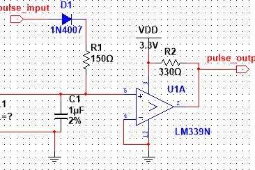
The use of a center tapped transformer, which I got from an old digital clock, made the design easy. With this type of transformer you can easily make a power supply using only two 1N4004 diodes instead of 4 diodes and create a zero detection circuit using the two 1N4148 diodes and the BC548 transistor.
The zero detection circuit is connected to the interrupt pin 5 of the PIC12F675 and generates an interrupt every 10 ms because of the 50 Hz mains power cyclel. Depending on the selected dim level, the PIC will trigger Triac BT138 sooner or later during the 50 Hz cycle using the optocoupler MOC3020. The later the Triac is triggered during the 50 Hz cycle, the lower the brightness of the lamp.
The first figure shows the trigger pulse of the Triac when the lamp is at its minimal brightness, in fact it is off because the Triac is triggered when the mains power is at the end of its 50 Hz cycle. The top signal is measured after the 1N4148 diodes so it is a rectified signal that is shown here.
The second figure shows the trigger pulse of the Triac when the lamp is at its maximum brightness. As you can see the trigger pulse is not completely at the start 50 Hz mains power cycle which is caused by the fact that the zero detection circuit does not generate an interrupt exactly at the start of the mains power but later. This means there is a small increase in the brightness of the lamp from the maximum brightness to completely on but this is not visible.
The trigger signal for the Triac can be moved anywhere between the min and max values so controlling the brightness from completely on to completely off. This works well for larger, e.g. 40 Watt, lamps but also for smaller lamps like the 15 Watt lamp that I used. Not all dimmers you can buy are able to dim 15 W lamps but this one can.
The third figure shows the situation in which the lamp is dimmed to a low brightness by triggering the Triac near the end of the 50 Hz cycle.
In this design I used a crystal of 20 MHz for the processor clock since the on-board oscillator of the PIC is not accurate enough for this purpose.
Step 3: Building the Electronics
You can build the circuit on a breadboard but be very careful with the Fuse and the Triac that switch the mains power. Do not touch the mains power in any way!
In the pictures you can see the circuit as I build it on the breadboard. Normally I try to use as less as possible wires that cross other wires (the green and orange ones). The housing for this dimmer is a bit oversized but I could not find a smaller one.
I did not measure the power consumption of the circuit but I think that most power is consumed by the two LEDs and the optocoupler so I guess the whole circuit draws about 40 mA.
Step 4: The Software and the Operation of the Dimmer
As already mentioned, the software is written for a PIC12F675 but you can also make this for your Arduino. It was written in JAL and the program has quite some comments that explain what the various parts of the software are doing. Since I did not use any specific libraries the total code size is 533 bytes which fits nicely in the 1k program flash memory this specific controller has. This PIC has EEPROM on board which is used to store the last selected operating mode and the last selected brightness value.
The software performs the following main tasks:
Read the EEPROM at power on and use the stored operating mode and brightness level. At first startup nothing is stored in EEPROM so it uses a default value. The default is set to lamp off and a brightness level of about 50% of the lamp brightness.
Read the push button and change either the operating mode or the brightness level.
Trigger the Triac synchronous with the 50 Hz mains power to switch the lamp on, off or dim. This trigger signal is generated on an interrupt basis using the zero detection signal as input.
Store any change in operating mode or dim level in EEPROM.
Note that the software also has a test function. If you press the pushbutton while switching on the power of the dimmer, the dimmer will go into an endless loop, changing the brightness from minimum to maximum and back again. You have to switch the dimmer off and on again – and not press the pushbutton – to get the dimmer out of this mode.
The video shows how it all works in practice. In this video you see the following:
The dimmer is switched on. The green power LED is on and the lamp is off.
Pressing the push button once turns the lamp on.
Pressing the push button again switches the dimmer to dim mode. The amber dim LED is on indicating that the dim mode is active and a default brightness level is used.
Pressing the push button again switches the lamp off.
Pressing the push button once turns the lamp on.
Pressing the push button again switched the lamp to dim mode.
Pressing and keeping the push button pressed while in dim mode increases the brightness of the lamp.
Releasing, pressing and keeping the push button pressed while in dim mode decreases the brightness of the lamp.
Switching the dimmer off and on again (green LED goes off and on) sets the dimmer to the last operating mode. In this case it was the dim mode with the last brightness value (amber LED is on).
Pressing the push button switched the lamp off.
The Intel Hex file and the JAL source file are attached. I renamed the JAL file from ‘.JAL’ to ‘.TXT’ for readability.
Have fun building your own project and looking forward to your reactions.
Welcome to our group instructables page. Here, we’ll break down all the steps you’ll need to build the “It’s 5 O’Clock Somewhere” portable clock.
What is it?
It’s a portable clock, connected to your local wifi, or paired with your phone, to show you the current time and where in the world it’s 5 o’clock. A tongue in cheek take on the expression “it’s 5 o’clock somewhere”, which alludes to the time in which the end of the work day has arrived, and happy hour has begun. Our device is a constant reminder that somewhere, someone is enjoying the end of their day.
What does it do?
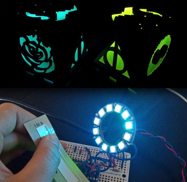
It displays the name of a city in which it is currently 5 pm, along with the current time in your timezone. The electronics are visible through a pyramid shaped case, made from laser cut acrylic. This makes for a great portable desktop show piece.
How Does it do it?
The device makes use of the Particle Photon to connect to WIFI and determine the user’s location. The photon is programmed to capture the user’s time and location, and then determine other timezones accordingly. The time and city then gets displayed on a 0.96″ OLED screen.
Parts List
Particle Photon
Particle breakout for lipo battery
Lithium Ion battery (1200mA)
0.96″ OLED display (this one)
2 x 1/4 sized protoboard (we recommend this kind)
7 x 2″ pieces of 22awg wire
–//Encasing//–
3mm thick acrylic sheet (one sheet of 15″x13″ acrylic allows for enough material for 4 of these boxes)
Double sided tape
(see step 4 for complete bill of materials)
Tools list
Soldering Iron
Lead-free Solder
Sponge
Flux
A laser cutter (we recommend finding a local shop that can do this for you).
Exacto knife
Gorilla brand super glue
This project was created in collaboration by Jacob Cram, Colin Borins, Nathaniel Leslie, and Luke Garwood
Step 1: Soldering
Since there are two protoboards, we’re going to call them protoboard1 and protoboard2 for clarity. Also, we’re assuming you’re working with the adafruit 1/4 sized protoboards, if you’ve chosen another set of protoboards then the rows and numbers may not line up exactly, but hopefully you can follow along anyway.
Connect your OLED screen to protoboard1. Solder the OLED screen’s pins to protoboard1’s row B, holes 5 through 11. B5 — CS, B6 — DC, B7 — RES, B8 — D1, B9 — D0, B10 — VCC, B11 — GND.
Solder one end of approximately 2 inches of wire to A5
Repeat this with the 6 other pieces of wire, connecting one end of each wire to A6 through A11.
Now take your lipo breakout module and line it up with the holes of protoboard2 (we’ll be inserting the wires through both the protoboard and the breakout module and soldering them in place). *the reason we need the second protoboard is so that the device sits evenly on both sides. If you’d like to alter the design, you may not need this.
Take the wire connected to A5 (or CS on the screen) and thread through to D4 on the breakout, solder in place.
Take the wire connected to A6 (or DC on the screen) and thread through to D3 on the breakout, solder in place.
Take the wire connected to A7 (or RST on the screen) and thread through to D5 on the breakout, solder in place.
Take the wire connected to A8 (or D1 on the screen) and thread through to A5 on the breakout, solder in place.
Take the wire connected to A9 (or D0 on the screen) and thread through to A3 on the breakout, solder in place.
Take the wire connected to A10 (or VCC on the screen) and thread through to 3V3 on the breakout, solder in place.
Take the wire connected to A11 (or GND on the screen) and thread through to GND on the breakout, solder in place.
That’s it! You’re electronics are all set!
Step 2: Acrylic Box
Download the file we’ve provided in the Files and References section
Take that file to your local laser cutter.
Once you have the pieces, start by peeling away the protective vinyl from the acrylic
Once all the pieces are peeled, take one of the triangular pieces, and apply glue to one of the edges.
Take the rectangular piece with the hole cut out, and connect it with the notched side on the triangular piece you just put glue on.
Once dry, look to see which end of the rectangle the hole is closer to. This edge is where the bottom of the device will go, we want to attach the bottom last, so apply glue to the other edge of the triangle.
Connect the rectangular piece again.
When dry, apply glue to two sides of the second triangular piece, and connect it opposite to the first triangle.
*Suggestion for when you put the electronics in the box. We’ve scored two slits the width of the electronics (a little wider than your battery), on the bottom piece with an exacto knife. This forms two grooves for the protoboards to sit it. Now you can apply glue to the bottom edge of the protoboards and set them in those two grooves for a better stick. We also applied a bit of double sided tape to the bottom of the Lipo battery so that it can also be stuck to the bottom piece of the box.
Step 3: Programing the Photon
If you’re brand new to Particle Photons and you’ve opened yours up for the first time, we recommend following the steps outlined in Particle’s documentation to help get you started and connected to WIFI. You can find directions at https://docs.particle.io/guide/getting-started/start/photon/ .
From the Photon IDE, open the folder entitled “5oclocksomewhere-BranchOne” from the unpacked zip file. Opening this folder will allow you to integrate all the required libraries.
On the left hand side, there’s a list of all the files included in the “5oclocksomewhere-BranchOne” folder, you’ll want to open the fivepm.ino file if you want to make any modifications.
Make sure your device is connected to your computer, and that it’s selected in the bottom toolbar (click to add it from the list if it’s not).
Compile and flash the code to your device by clicking the lightning bolt in the top left corner.
And there you go!
Step 4: Files and References
Files included here are a bill of materials, a fritzing file with the circuit diagram (http://fritzing.org/home/), and the illustrator file for the acrylic pyramid case
Having already experimented with creating a robot using a cheap motor driver board, I decided to look at the one provided by Kitronik, I liked the look of it as it came with easy to use screw terminals to attach wires and had 4 inputs by default.
The nicest thing is that if you get the v2 board (second version) it also has an expanded section which allows you to solder a 20 pin header onto it and use the full range of extended Microbit ports.
Aims
Create the robot chassis keeping costs to a minimum or allowing to reuse old parts you may have available.
Reuse old motors I had (in this case Tamiya motor gearbox combinations)
Create a good base I could provide in simple kits to students attending one of the workshops I plan to run this year.
Add IR sensors to create a way for the robot to avoid close objects.
Add neopixels so it can use different colours and sequences to show what the bot is doing
Allow more sensors to use the expanded pins on the motor driver board perhaps in future updates
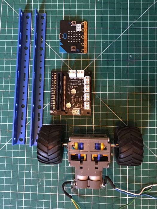
2 x motors and wheels of your choice, I used Tamiya motors with gearboxes as I had some already. link
4 x AA battery box for the motors, rechargable batteries or a power supply of your choice
Some plastic strips or other to make a chassis out of. I used a couple of these link
female to female jump leads to connect microbit edge connector to IR sensors and Motor board
1 x caster wheel from DIY shop / store
Some plastic sheet, I used some A4 sheet plastic sheets 1.5mm thick, which you can score with a knife and snap, or can cut with scissors. This is great for panels on your chassis to to build sides later on and enclose all the electronics. link
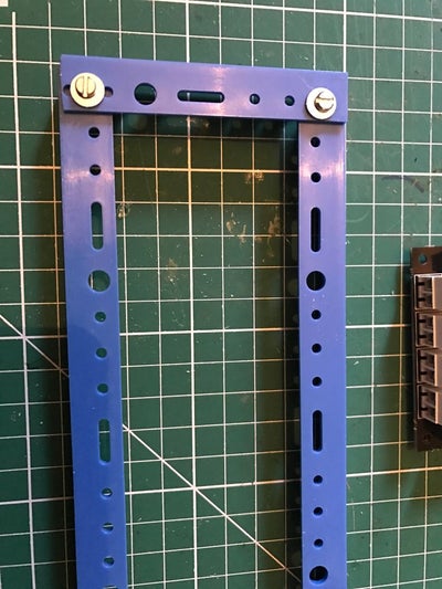
For the chassis I wanted to start with a basic frame that would give me options later to perhaps build upon, so adding a body to cover the electronic could be a future option.
I started with 2 plastic strips and cut them to a length I thought my bot with 2 wheel drive and a caster wheel would need.
I placed the motors in place to work out the width I would need and attached them using the 2 fixing holes available. I cut the chassis to allow the motor shafts to stick through the middle of these two side struts of the chassis.
Next I fitted the front and back struts connecting with a single screw and nut at each corner. I had to drill these holes with my dremel as the holes already there were not exactly where I needed them.
I decided to put it on my chassis with the expanded pins section at the front, and face the microbit that way as well when slotted in place. Like many microbit expansion boards they allow the microbit to be fitted in either direction. Its important to read the expansion boards notes to see if there are any limitations when doing this such as some pins not available.
I also added the wheels to the motor gearbox output shafts and fitted a rear castor wheel.
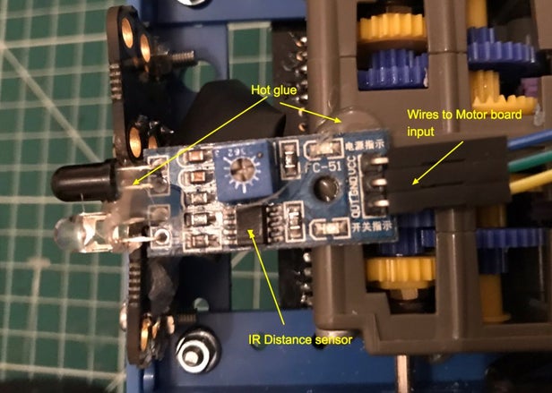
Step 3: Adding an IR Distance Sensor
Initially I wanted to get used to using just one of these sensors, I had tried before using Arduinos and the Crumble controllers however I had found them very sensitive, and they come with a sensitivity adjustment available by screwing in or out an onboard potentiometer. My plan this time was to find settings that worked and try and get them to work each time and not need constant readjustment before use. My thoughts here were if I can use the accelerometer as a backup I can then not be too concerned if a sensor doesn’t behave as I should have another way of detecting movement and potentially cutting power to the motors.
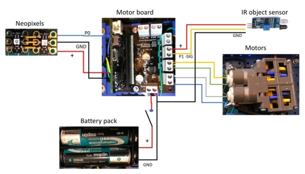
Step 4: Complete Wiring
The wiring is reasonably straight forward, refer to the image here as a guide on what I did.
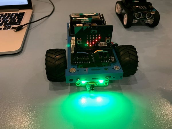
Step 5: Add the Neopixels
I also wanted to add some neopixel lights so the bot could tell me by colour what was happening as well as using the built in microbit’s display.
The neopixels I used were sold as a Crumble microcontroller accessory, I like these as they are not too small to work with and have holes to add male ended pins or wires, or can be used with crocodile ended leads.
I decided to use two side by side so first soldered 3 pieces of wire between them connecting the 3 connections required.
Positive, negative and signal
I then soldered 3 jump lead wires which were female to female so they would connect easily to the extended motor controller connections, where I had earlier soldered the header pins.
These I pushed in so I connected a Positive, negative and signal connection to these extended pins.
The pin you use on the extended header needs to be capable of analog output, so for this I used Pin 0.
I tested this with a simple micro python script (see image), this allowed me to test both neopixels, you could add more and the loop here would cycle through them all.
Step 6: Battery Power Supply, Holder and Power Switch
The good news is the Kitronik motor driver board also powers the plugged in Microbit. So using a 4 x rechargeable AA battery pack in a holder and adding a switch is the perfect combination, If you have some Lipo battery pack that would be lighter than this, but its what I already had available.
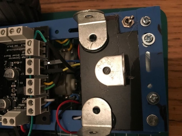
I hot glued some metal angle brackets used for small shelfs from a DIY store. These would stop the battery pack to slide about when the robot moved, but would be easy to remove to recharge or to access other parts of the chassis.
I added a switch and attached it to the chassis by creating a hole to push it through, and then soldered the wiring required.
When deciding what type of connectivity your next project will use cellular tends to be considered an expensive alternative to WiFi or Bluetooth. This tutorial is meant to break that way of thinking and show how easy and inexpensive cellular could be with the right provider and tools.
Below is a list of components which could be picked up for between $12 to $19. All the components in this tutorial came from HackerBoxes #16. You can buy box 16 from Hacker Boxes’ store. They also wrote their own Instructables, found here. For cellular IoT connectivity, we’re using Hologram.io.
First, I work for Hologram on the Developer Relations team. As a Hologramer, I think they’re naturally awesome. As a developer, I think they’re awesome for another reason, what they offer is unlike anyone else.
Kilobyte billing at $0.0006
Each SIM provides worldwide coverage on over 180 networks
In the States, Hologram leverages the networks of T-Mobile, AT&T, and Verizon.
2G, 3G, and 4G
Lowest monthly network fee at $0.40 per month per SIM
Self-serve device management dashboard where I can activate or pause my SIMs instantly
Pretty handy data router that allows me to send my data to multiple SaaS and cloud providers
and a bunch more
Step 1: Activate Your SIM
First thing’s first. Let’s activate our SIM and grab the device key which we’ll need for our sketch.
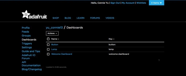
Head over to Hologram’s dashboard (https://dashboard.hologram.io), log-in, then click the blue Activate SIM button in the top right corner.
Fill out the activation form; it typically takes 1 minute for a SIM to be activated and register on the network.
After activation, you’ll see the device list. Click on the newly created device.
On the device page, go to Configuration then generate new Router Credentials.
Generate and copy the eight digitdevice key. We’ll be using this key in our Arduino sketch.
Step 2: Wire-up Components
Attached are graphics showing how to wire up the SIM800 module along with a button and LED.
IMPORTANT: Verify you insert the SIM correctly, see my images above.
IMPORTANT: Make sure to attach the external antenna.
D12 > Button
D13 > LED
D10 > SIM RST
D8 > SIM_RXD
D7 > SIM_TXD
Connect all GND and 5V
Step 3: Arduino IDE Sketch
Next, we need to program our Arduino to control the cellular module, button and LED. Luckily Hologram has helper library specially made for the SIMCOM SIM800 and SIM900 family of modules. The helper library also has an example sketch of this tutorial. Let’s set it up.
Open the library’s ‘Blink’ example (see the second image above)
In the sketch, all PINs should already be defined. All that’s left for you is to enter your 8-digit Cloud Device Key (you got this in step 1).
Connect the Arduino to your computer and upload the sketch.
Optional: Open the Serial Monitor to watch the cellular module initialize.
Hologram’s SIMCOM Helper Library makes it super easy to send and receive Data and SMS. I’d encourage you to check out its readme for a full list of functionality: github.com/hologram-io/hologram-SIMCOM#reference
Step 4: See Data, Send Data
OK, we have our Arduino wired up and working! But what is it doing?
If you read the sketch, you saw it was collecting stats each time the LED toggles. Every 2 minutes it sends those stats up to the Hologram cloud.
Back on the device page in Hologram’s Dashboard, click the tab labeled Data Logs (image 2). If you’ve toggled the LED a few times and its been 2 minutes, you should see a JSON object containing toggle stats.
Another cool thing the Hologram SIMCOM library allows is inbound messaging. Our sketch will toggle the LED if we send it a message with the string “LED”. Let’s do that. On the device page in the Hologram Dashboard, click the tab labeled Messaging (image 3). Send a TCP message containing the string “LED” to port 8888. In a few seconds, your LED should toggle!
Folks usually post data into the cloud because they want to send it somewhere for storage or analysis. Check out Hologram’s Data Router documentation on how you can pass data to IFTTT, Losant, and others cloud platforms.
Everything we did through Hologram’s Dashboard is possible through their public API too, including sending inbound messages to your devices from your servers and other IoT devices. Checkout Hologram’s REST API documentation or Node NPM package.
There are many many sensors. I’m covering the very basic ones in order to give reader the requirements to get started building “something”. That might not be rocket science but that should actually work.
If you don’t have the parts, watch out for my upcoming instructable “Sourcing Electronic Parts From Asia“.
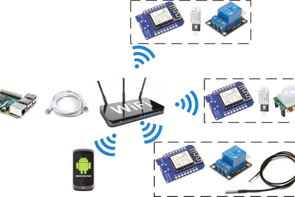
Let me add a few buzz words : IoT, ESP8266, Homie, DHT22, DS18B20, home automation.
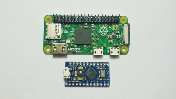
This instructable uses D1 Mini clones. These are WiFi enabled Arduino compatible controllers using ESP8266 chip. They ship in very small form factor (~34*25mm) and are dirt cheap (~3-4$ for clones).
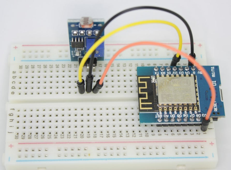
I’ll illustrate each build using a D1 Mini, a breadboard and some sensor(s). I include a Bill Of Materials (BOM) for each but will skip obvious things like jumper wires and breadboard (mini or full). I’ll focus on “active parts”.
The D1 is quite breadboard friendly but will save only one row of pins up and down. Each example will have the D1 on the right side and the components on the left side. The upper and lower power rails will be used to carry either 3.3V or 5V.
Note
Homie examples are built as “.ino” sketches for Arduino IDE. My own code is however built as “.ccp” for PlatformIO.
This will make very little difference as sketches are simple enough to be copy/pasted whatever your tool of choice is.
Step 2: Temperature & Humidity : DHT22 / DHT11
Building the device
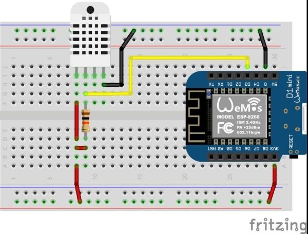
The DHT22 uses :
One digital pin to communicate with the controller, connect it to D3
Two wires for power (3.3V or 5V + GND)
The digital pin must be kept high (connected to power), for this we use a resistor between power rail and data pin
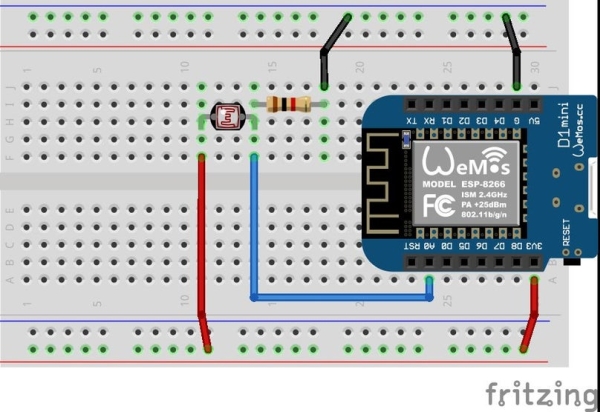
(Sorry, don’t have a Fritzing component for the digital photocell)
The photocell digital module uses :
One digital pin to communicate with the controller, connect it to D3
Two wires for power (3.3V + GND)
Its possible to use an analog photocell but this is not documented here, see Adafruit excellent article “Using a Photocell“.
Note: In this example there’s a potentiometer on the sensor board. It is used to set the limit between “light” and “dark” ambient light. When reading 1 light is off, therefor reading 0 means light if on.
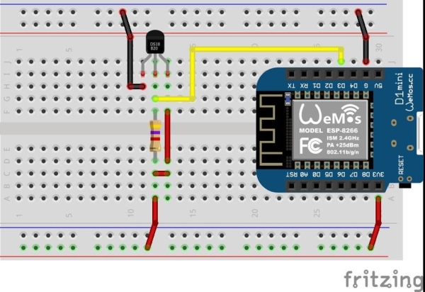
The photocell analog sensor acts as a resistor. It will connect between an analog input and 3.3V.
A resistor is put between GND and data pin to create a voltage divider. The purpose is to create a known range of values:
If there is no light, photocell will basically block VCC, thus connecting GND to your data pin : Pin will read nearly 0.
It there is a lot of bright light, photocell will let VCC flow to the data pin : Pin will read nearly full voltage and as such near to max (1023).
Note : Analog pins values are read in a 0-1023 range using analogRead. This is not practical to deal with 1 byte values, for this the Arduino map function will help reduce from 0-1023 to (for instance) 0-255.
For calibration of min/max values for your sensor, use a sketch like this one from Arduino.
This instructable is a very short one to explain basic monitoring.
To go further we’ll need to connect relays, IR emitter… This will hopefully be covered later on as free time allows me to. The major difference is that we won’t just “read” (is there light?) but also “write” (turn light on!).
Paper, Rock, Scissors is an old, simple game. Basically each player takes turns to make a shape with their hands and depending on the combination one player wins each round. A more detailed description of the game can be found here
The game is usually played between two people with no equipment but this instructable shows you how to modernize the game and automate the reading and scoring of rounds with gloves that sense the shapes!!
Here is a video of what to expect:
Step 1: Parts You Need
The game is built around Arduinio, 4 ‘FlexSensor’ strips and two old gloves you don’t mind losing. There are some other parts too so the full list is:
1 x Arduino Uno
4 x FlexSensors 2.2″ strips like these. They were apparently the sensors used in the original Nintendo Power Glove and basically act like variable resistors
2 x Right hand gloves. Cheap or old gardening / DIY gloves are best, you need to be able to sew into the fingers
6 x LEDs, 3 Blue, 3 Red
6 x 470 Ohm Resistors (for LEDs)
4 x 20k Ohm Resistors (for FlexSensors)
1 x 5V Piezo Transducer Buzzer – Like this example
4 x 1 meter (3 feet) 2-core wire
Vero board – or breadboard if you want it a bit less permanent
about 20 wires to connect the Arduino and the breadboard or veroboard
1 x small box – To house it in. I used a plastic box that the flexsensors came in but any small box will do
Some soldering skills!
Step 2: The Gloves
First solder a 1 metre length of the 2-core wire to the two ends of a FlexSensor strip. Use heat shrink or electrian’s tape to insulate the connections from each other. It should look like the picture. Repeat this 3 more times so you have 4 sensors on 4 lengths of 2-core wire.
The next step is to fix the FlexStrips into the gloves. When you think about it all 3 possible shapes (Paper, Rock & Scissors) can be determined if you know what the middle two fingers are doing
Therefore you need to sew in two sensors into each glove over the two middle fingers. You want the middle of the strip roughly over the main knuckle in each finger to get the best read. You can also use some super glue for this step if you like but it is harder to switch out a sensor then if one fails.
Lastly group the 2 lengths of wire that come out of each glove. You can put some stitches around it in the first 2-3 inches to keep it attached to the glove then after that attach the two wires for each glove together with zip ties or electrician’s tape. this means that each glove only have on cable then attached with 4 cores. The other end of each needs stripping ready to solder into the veroboard
Step 3: The Circuit
Before building out the rest of the project I highly recommend trying it all out on a breadboard first before building it out on the veroboard and soldering it together. I include a picture of my messy prototype on breadboard although this really helps get the cirtcuit right and test the components
I am not going to explain each detail but I have instead included a kind of circuit diagram to show how all of the components are connected.
Some notes on this:
If the fingers or not in the exactly right order it can be corrected later with the code
You can use other outputs. I used 13 for one of the LEDs so this also flashes while the code is uploading
Step 4: The Code
Once you have built out the circuit (hopefully on breadboard at first) it is time to test out the code. Luckily for you I have attached my code so you don’t have to write it but you might need to adjust it and you can certainly extend it. The code is fairly simple
Load the code onto your Arduino Uno Board. If you don’t know how to do that I suggest reading this first
About the code:
The code causes the buzzer to make a series of beeps. In each group of beeps the third beep indicates that the gloves are being read
There is debug code that writes out to the serial monitor. In the Arduino code editor click on Tools > Serial Monitor first. This will tell you what the circuit is reading and who it thinks won. An annotated example is included here
“NOREAD” in the SM output indicates either an unexpected shape is encountered (only ring finger bent) or something else went wrong with the read
The parts of the code that look something like this “((flexSensorReading <=400) && (flexSensorReading2 <=350))” are testing whether the flex sensor has exceeded a threshold, i.e. is that finger bent or not. Depending on what reads you get in the monitor you might need to adjust these thresholds. Also this monitor can be used to determine if the fingers are wired up the same way as intended in the code.
You can change this line “boolean soundOn = true;” to “=false” to turn off the buzzer beeping if it is annoying you while testing / debugging
The gameMode variable is not used but I will describe what the idea was here in the next and final step
The code scores each player up to 3 points since we only have 6 LEDs (3 each) at that point the celebrate function is called to sequence the LEDs and then flash the winners set of LEDs. Try changing this if you want a different celebration with the beeper too!
Step 5: Possible Further Work
I packaged the project in a plastic case and cut holes for the LEDs, glove wires and the USB cable. I used a mini label printer to label the 2 sets of 3 LEDs and then sealed with more tape. This is really all you need to do but if you want to do more then here are some ideas on how to carry on with other tweaks:
The game mode ‘Chaos’ is not coded but the idea is that there is no audio cue as to when the glove read is taken. This means you have to try to stay ahead of your opponent at all times so that when the program randomly samples the gloves you are in the winning position. The idea would be to put a switch on the circuit so the players could select the game mode and this would be read by the Uno
Currently there is no way to restart a game again once started. You could alter the program to read only ring finger bent on both gloves as a kind of start again instruction. Only ring finger bent is otherwise not a valid shape
I have 6 LEDs, 3 for each player but there is enough outputs on Arduino to extend this to up to 7 for each player if you like
I hope you have fun both building and playing Electronic paper, rock scissors!
If you like this instructable please consider voting for it in the microcontoller contest!
Burning patterns into stuff with the focused suns rays…. about the level of eighth grade earth science before this subject was eliminated by our current Secretary of Education. But what if instead of just killing small arthropods with a death ray and then seeing spots before your eyes for ten minutes you could neatly carve beautiful figures with a solar Etch a Sketch. Controlling the Sun can be done with either moving the beam with a servo-motor mirror system or moving the target. The utility of Laser cutters and CNC machines is demonstrated nearly everywhere–you just need a lot of cash or a nearby well stocked Maker Space to participate in this blooming culture, or do you? The sun is free and the tools to carve into blocks of frozen yogurt or crackers or chunks of wood are easy to obtain from China or Adafruit. This project was done as another instrument to use at Burning Man–the ubiquitous sun, its portability and you can run it for the whole week on a car battery! The output is a little limited–for simplicity sake I designed it to do angles and straight lines but you could jazz it up for circles and curves.
Step 1: Get Your Materials
Adafruit Feather 32u4 Basic Proto –a wonderful little all around board from Adafruit. I have used it in my last several projects and it works flawlessly. I powered the board through the USB.
DC Motor + Stepper FeatherWing Add-on For All Feather Boards works well with the Adafruit feather and since it uses I2C connector it leaves all the other pins free for sensors etc. This board requires a separate power supply for the steppers and is easily setup with another wall wart or another tap off the car battery.
http://www.ebay.com/itm/2-Phases-4-Wires-DC-4-9V-1…I used this setup on the last project https://www.instructables.com/id/Mechanical-Moving…and they are reasonable cost for setting up a cheap, lightweight x-y control system. I have had limited success with speed control on them and you have to be careful to not tax their weight moving limitations. They have a rating at 4 to 9 volts listed and I have never overheated them. These have 20 steps per rotation and 18 degrees/step.
2 axis Joystick–Parallax Inc. Directional control of the suns carving beam–I originally programmed this for speed and direction but since speed control is limited with these steppers I eliminated it.
Light Duty Hobby Servo This is to operate the shutter. You really need a way of turning off the sun else your whole kit will burn up.
8.3″ x 11.75″ LARGE PREMIUM GRADE Fresnel Lens –these are Fresnel lenses that are used for focusing the suns rays onto your target. Get the slightly more expensive bigger ones. This allows you some latitude in gathering rays if the sun isn’t as strong that day. My experience is here in Alaska in the spring and I had to cover up nearly 3/4 of the lens surface or else the target would burn up.
Step 2: Wiring It Up
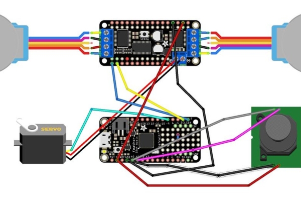
The Fritzing diagram is pretty easy to follow. It is a simple I2C connection between the Stepper Board and the Feather. The power for the board itself comes from the 3 volts on the Feather. The power for the steppers must be provided separately — in this case I was using a car battery for the whole setup so I used a car USB charger for providing power both to the Feather and another line for the Steppers. The car battery also provided power to the back-up camera and monitor. If you are using 110 line voltage you will need a couple different wall warts to provide 12v for the camera unit and 5 volts for the Feather/Stepper Board and Steppers.
The Servo is controlled off of pin 9 on the Feather and I just linked its power to the same source as the steppers. Make sure you use a common ground. The Joystick is connected to A0 and A1 and power and ground on the Feather. The analog inputs sample the voltage from the potentiometers on the joystick and the code controls the x and y directional movement accordingly. You should run the output of the joystick through the serial port just to get an idea that your output mirrors mine or if not set the limits accordingly in the code.
The stepper motors are wired with screw terminals on the Stepper board. As usual make sure that pairs of the matched coils are linked to adjacent screws–they are unmarked on the motor, but a continuity tester will reveal the pairs. Further info and tutorials on all these subjects are available on the Adafruit website. I don’t work for them ( wish I did…) but I have benefitted greatly from their tutorials.
As before I suggest testing the whole unit on a bread board before committing yourself.
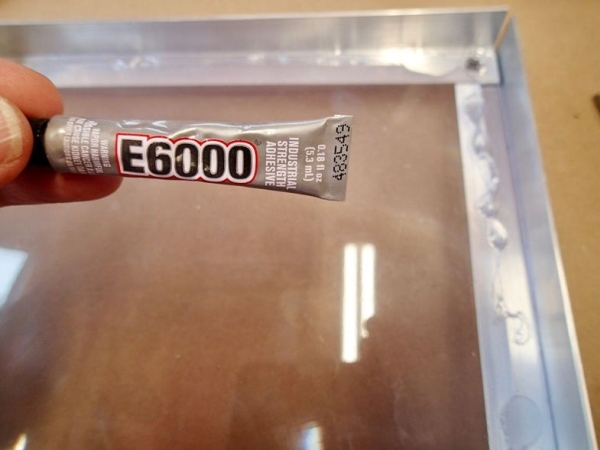
Step 3: Building It
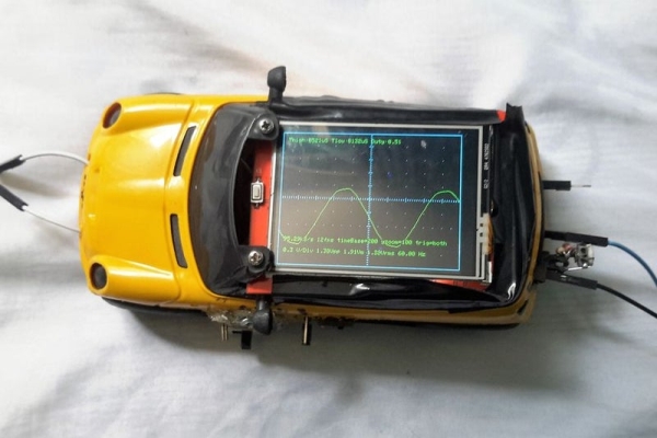
The first step is to frame in the fresnel lens. I use aluminum channel and screws for this construction. The lens panel has to face the sun with groves out. Seal it into the frame with E6000 glue–great stuff. You must determine the focal length for your particular model of lens–mine was exactly 12 inches. You do this in the usual way by imaging an object at optical infinity–the sun and measuring the distance from the screen to where it comes into focus. This is where you will place your x-y gantry. I built mine on plexiglass and mounted it on four spring loaded screws so I could adjust its position for thicker and thinner targets (frozen tofu cakes….) The rest of the frame is constructed around the gantry and lens and provides a location for mounting of the servo controlled shutter. A closeup view of the construction of this linkage is provided. The shutter itself is a cut circle of very thin aluminum–locate it close to the target–you have to move it around to make sure it obstructs the beam well but not too close where it will get hot. The viewing camera I put under the target–it has a very wide field so can pick up the action without being in the way of the beam. I used this camera and monitor setup as you are imaging the sun and it is not a good idea to look at it for any length of time–even with sunglasses. I found that with heavier objects placed on the gantry the vertical stepper had trouble moving so you can see I installed a counterweight pulley system which can be adjusted accordingly.
The electronics bundle with joystick I located on the upper back of the gantry in a plexiglass sandwich with the camera monitor on top–see photo.
Step 4: Programming It
The final code for the Solar Draw has several parts. The drawing portion directs the x-y gantry around in a pattern set up in the first section of the code in dotMatrix. It is a 2 dimensional matrix that lets you describe the movements of the x and y gantry. The number of steps is indicated by the number of rows and the movement of the x and y steppers is described in the 6 column numbers. Column 1 and 2 tell if x and/ or y are moving–designating 1 for yes and 0 for no. Column 3 and 4 tell which direction corresponding x and/or y are moving–1 for forward 0 for backward. Column 5 is total turns of the screw or distance travelled and column 6 is shutter open (1) or closed (0). This lets you program straight or angled lines in as many steps and positions as you want.
The setup section of the code executes this pattern once and the loop function sets up control to the joystick. If you want only joystick control you can eliminate this first section. I know there are many Arduino-controlled CNC hardware-software combinations out there and feel free to adapt them to this unit.
The forward/backward adjustment and movement are trial and error when you are setting this up–caused by differences in how the steppers are connected–you basically have to turn the software on to find out which way its going to go and then adjusting it. There are no end stop switches to tell the computer where the x-y gantry is at startup–you can add these if you want to like in my last project. You can adjust this initial position with the joystick and program the gantry to return to the start position when programming the drawing matrix–this will allow you to keep starting the program at the same spot each time.
Step 5: Using It
This is one of those projects where your not sure what is going to happen when you finally line up the sun and turn it on. The first thing was it caught fire. The sun is incredibly strong and the power density at the focal point has to be mitigated by either covering up most of the lens with velcro adjustable screens–see photo above or maintaining the shutter in a closed position while not moving the gantry. Having the shutter closed for a few seconds in between movement excursions allows the substrate to cool down and proceed with your line. Depending on what your lasering–frozen tofu, bread slices, bed sheets or Ant farms you will have different tendencies to fire activity. I was originally going to build the unit with a solar following circuit to mount it on so that it would follow the sun as you were using it, but I found that it was easily mounted on a portable light stand from the big box store and it position relative to the sun could be easily manually adjusted every ten minutes or so. This made it much simpler. If I make it to Burning Man with it this year I will see you out on the Playa.
Another basic Arduino project is waiting for you to build! This exciting project will allow you to create an awesome L.E.D Music Visualizer using few components such as a Microphone module, resistors, L.E.Ds, and Arduino. This project is perfect for those who really loves music. Everybody loves music (including me) so that’s why I made one for my own entertainment purposes. Basically, this project will convert the sounds into lights. Yeah, that’s the only purpose of the project to convert the music into reasonable lights so we are able to visualize what the music is all about. For example, if the music is a kind of Dance genre then the music visualizer will convert the music into dancing lights animation effects (pretty cool stuff). Another example, if it is Rock music the corresponding output will be rocking light effects. Is it cool enough to have this kind of stuff in your home? For me, it is yes!
If you have no time to read this whole documentation in creating your own Music Visualizer please watch the video tutorial I’ve provided. For a great detail in making this project, I recommend to you to take your time to read this documentation. Plus, this documentation has detailed photos to guide you through the project without getting errors or problems. Please consider subscribing to my YouTube Channel for more future updates and projects.
My Inspiration
When I am browsing on Youtube to watch some interesting Arduino projects, I found something that really inspires me to make one for myself. Yeah! I found this video and I really like it so that’s why I started this project and make my own version to play the same song. Owl City – Fireflies is my dedicated song for this project (I am proud that I am certified HootOwl). I ended up with this video for my own version!
How does it work?
Basically, the project is powered by Arduino a very popular microcontroller for all makers out there. For this project, I only use Arduino Nano (why I am still using this? you know the reason why I am always using this stuff in every project that I have because it is small, same performance as Arduino Uno and the important thing is… it saves space.) to serve as the brain for this project. The ear of our project is the Microphone Module, the only task fo this module is to detect the sounds from somewhere and converts it into numerical values.
Here’s the process on how the sounds will convert into lights. The Microphone module receives sounds then the sound will be recorded into numerical values. Then the Microcontroller will read the numerical values to check if the values from Microphone module reaches the threshold values of every L.E.D in the project. If the sound values greater than or equal to the threshold of the L.E.D then the L.E.D will turn on and vice versa if not.
I setup unique threshold values for every L.E.D so that it will create nice and smooth light animation effects from music, noise or even sounds. So that’s it so simple, you can check the code if you want to learn more about the project. If you are already a developer and you want to improve my project please visit the gist where you can contribute and download the code for this project. Any help is highly appreciated.
Do you want it? Let’s make it!
I have a lot of fun creating this stuff in my workshop even documenting this project to post here in Instructables. I hope you will enjoy creating this as I enjoy making it. Do you really like it? well, make one for yours! Please follow all the steps here to serve it as your guide to make your own Music Visualizer.
Playing some music!
I made some videos on playing music with my own music visualizer. I have posted it on youtube and I want you to check these videos out! Please subscribe to my youtube channel and please leave a like! Below is the list of some songs I’ve recorded with my music visualizer. I hope you will enjoy it!
The extended version is composed of two Arduino (Nano and Uno) to run. It is composed of two layers of L.E.D just imagine two set of music visualizer with different threshold ranges. Then I add RGB L.E.D to this version to add some little effects in the music that I am listening. So this version is customized and I don’t need to make a tutorial for it because this Instructable is the fundamental idea of it, you can make it your own extended version and please tag me in your project!
Inspire me!
I invested my time to work on this project. I give all of my effort to make this happen. Hours of documentation and editing. I am sharing this stuff on the internet to help others to learn and entertain with this simple project for free. This time, I need your help. By voting this project you are inspiring me to create more useful and basic Arduino projects to be shared publicly without any cost. I believe that knowledge is power and free. A little vote is a big help to me to continue my journey here in Instructables. So yeah don’t forget to vote this project here in Instructables. Just click the orange vote button in the top right corner of this project and also click the little pink heart above. Also, follow me here in Instructables for more future projects! Thank you so much for your support.
Sponsors
This project is made possible by ConnectedCities and Hive Electronics. For the complete kit for this project, you can check out their sites. Support them because they are supporting me. I made this project even if I don’t have enough supplies, tools, and equipment. Also, the quality of images and videos are not considered as high quality. I am using only my smartphone to document my Instructables. If you want to help me or support me, be my sponsor today! I will really appreciate it, with enough supplies, tools, and equipment, I am able to create more tutorials and DIY with ease without worrying about the quality of the documentation. Thank you so much for your support!
If you find my previous projects cool, please support me by voting them in the contest. Thank you for supporting me!
This is the time to do something amazing today! Come on, please continue to the first step!
Step 1: What You’ll Need
For this project, it requires few electronics components to be able to make your own LED Music Visualizer. All the parts can be obtained from Arduino Starter Kit available from Hive Electronics. Instead of buying the whole Arduino Starter Kit you can also purchase the complete kit dedicated to this project from Hive Electronics. All you need for this project is included in the kit. If you want to support me please purchase the kits from recommended electronic stores (which is my sponsors) such as Hive Electronics and ConnectedCities. Support them because they are supporting me!
You can buy the following parts individually if you live outside the Philippines. The stores are accepting orders only within the country of the Philippines. If so, you can buy these components on your favorite electronics store in your place.
Prototyping Components
1 x Full-Size Breadboard
1 x Small Size Breadboard
2 x Red LED
3 x Blue LED
4 x Green LED
9 x 330 Ohm Resistor
12 x Blue Jumper Wires
6 x Green jumper Wires
2 x Yellow Jumper Wires
2 x Red Jumper Wires
2 x Black Jumper Wires
1 x White Jumper Wire
1 x Orange Jumper Wire
1 x Arduino Nano with USB Cable
1 x Microphone Sound Detection Module
1 x 4400 mAh Portable Charger
1 x USB Meter (Optional)
Tools
Screwdriver with Flat-blade bit
Grab your parts and ready the bench because we are going to create something amazing today! If you have some questions regarding the parts list, please comment it below! I am willing to help you! Are you ready to build this stuff? Please go to the next step! See you there!
Step 2: Power the Line
Let’s power the line! Oh yeah!
All you have to do is to get your 2 yellow jumper wires and hook it up to the breadboard’s power lines. Why are we doing this? Because the full size breadboard is composed of two half size breadboard which is combined into one. So, basically the full size breadboard has two section. The power line in the breadboard is not connected as a whole straight line. They are actually cut in to half. That’s why we need to add jumper wires in the power line. Please follow the pictures above on how to extend the power line and act as a whole power line accross the board. After that you may now continue to the next step. See you there!
Step 3: Add Some Lights
Let’s add LEDs to the breadboard! Yey!
Get your 9 LEDs to hook up in the breadboard. In my version, I use 3 blue, 4 green, and 2 red LEDs. Don’t worry about the colors of LED to be use. It’s up to you what colors you will use for your version. Make sure it is 9 LEDs only. If you want to extend the number of LEDs you should modify the code to add additional LEDs to the project. If you know how to write code or extend my code, well, that’s cool!
Please check the photos for more details and serve as a guide for your project. After placing all the LEDs please jump to the next step! See you there…
Step 4: Wiring Anode
Here we go, after hooking up all the LEDs in the breadboard, we should add jumper wires for Anode of all LEDs. The Anode is the positive pin of the LED. In my case, I use the 6 green jumper wires for red to green LEDs. Please check the photos for more reference. Then I use 3 blue jumper wires for blue LEDs. Why am I doing this? This is because to make the project consistent and presentable.
Now grab your green and blue jumper wires and hook it up according to the photos I’ve provided. After adding all jumper wires please go to the next step!
Step 5: I Can’t Resist!
We are going to add some Resistor in the project! Why should we add a Resistor? If you want to extend the life of your LEDs well, you need to do this. In my case, I use 330 Ohm Resistor to protect the LEDs and add some brightness to the output of the project. My plan at first is to use 220 Ohm Resistor but sadly I am out of stock. 330 Ohm resistor is not bad because it makes my project slightly bright (not too much bright).
The resistor is directly connected to the cathode of each LEDs and continue to the Ground of Arduino. Traditionally, we are connecting the Resistor to the Anode of LED then continue to the output pin of Arduino. But it doesn’t really matter. They are almost the same. You can read more of it here, on what is the difference between connecting Resistor to the Anode or Cathode of the LED. Again, it doesn’t really matter if you connect your resistor to the Anode or Cathode pin of your LED, they are almost the same. The important thing is the Resistor must be present in your circuit or else your LEDs will burn and cook into a useless electronic component.
Please follow the photos I’ve provided to serve as your guide in placing Resistor to your breadboard along with LEDs. When you are done placing all the Resistor please jump to the next step! See you there!
Step 6: Wiring Cathode
Hello there! This time we are going to hook up some wires to the cathode pin of each LEDs. These jumper wires are the wires we are going to hook to the negative power line of the breadboard. In my case, I use all the blue jumper wires left. Go, grab some jumper wires left in your parts case and hook ’em all!
Basically, hook all the jumper wires from the end point of the resistors into negative power line of the breadboard. Please follow all the photos I’ve provided, make sure, all the connections are working, sometimes these jumper wires are defective. Do some connection test before anything else.
If all connections are working properly please jump to the next step!
Step 7: Preparing Microcontroller
Get your Arduino Nano and hook it up to the small size breadboard. If you don’t have Arduino Nano, you can use Arduino Uno. You already know why I keep using Nano it is because it saves space. After hooking up the Arduino Nano to your small size breadboard you can now upload the code to the Microcontroller. Go to the next step, I will guide you where you can get the codes and how to upload it! See you there!
Step 8: Nano Issue Fixing
Before uploading code to the Nano, we should fix first the most common issue in Arduino Nano which is unable to upload sketches from PC to the board. In my previous projects, I provide an explanation on how to fix this kind of issue in Nano. You can check out this specific step in my contest winning Instructable “ The Project E.M.I.L.Y.” You can read more here about fixing this issue.
To fix the issue in Nano, get your 2 pin jumper and 2 male pin headers. Then connect them as you can see on the photos showing how I connect them. After connecting 2 pin jumper and 2 male pin headers, hook it to the A6 and A7 of your Arduino Nano. Check the last picture for more reference. When you are done doing this please go to the next step so we can now upload some codes!
When turned off, it looks like an ordinary toy car that would entertain a kid for hours, but actually it is an oscilloscope kit in disguise!
The idea and also part of the code for this project came from another scope called STM-32-O-Scope (aka pigScope), which uses a more powerful Arduino cousin called STM32. I originally posted my version on hackaday, but now I’ve deciced to bring it here too, so it may help more people who don’t have a commercial oscilloscope and also becase there’s a contest happening
I use this tool daily to watch signals or as a second voltmeter and also to measure inductance of home-wound inductors. As the code is open, you may add, remove or improve features according to your needs.
As it’s more than just an oscilloscope and “oscilloscope and inductance meter” is too cumbersome, I named this little guy multiScope. Here’s what it currently does:
Measure inductances greater than 100uH with 10% precision
Display analog or digital signals with up to 1.7MS/s sampling rate
Temperature and pressure sensing (an extra feature)
3.3V USB/Serial adapter (FT232RL or something like that)
2.4 TFT LCD touch screen display (the display library I used was adapted to the model of the picture, but with some changes in code, you might be able to use others). Example link: 2.4″ TFT LCD Shield on eBay
A box or enclosure (may be something 3D-printed, an old box you have or even a plastic toy)
6-9V battery (I used 7.2 li-ion as it lasts very long)
Small switch (main power switch)
(2x)2.2K Resistor
LM7805 (5V regulator)
Parts for the inductance meter:
LM339 (comparator IC)
Resistors: 330R, 150R
1uF ceramic capacitor (the higher the precision, the better)
1N4007 (common diode)
Parts for attenuators :
2×3 female header socket
Resistors: how many will depend on how much attenuation you need, but they are regular resistors and trimpots.
Step 2: Add STM32 Support to the Arduino IDE
Before building our hardware, let’s setup our development environment. Here, standard Arduino IDE was used with an add-on called Arduino STM32. The guys who made it also host a forum called Arduino for STM32 that is not so beginner oriented as the Arduino forum, but people can discuss things related to the STM32 board family and also share their projects. There’s even a page with other oscilloscopes based on pigScope too, from which I’ve learned many things and maybe you will too.
OK, so do the following:
Make sure you have a compatible IDE version. They recommend 1.6.9, but I used 1.8.1 without any problem
Install Arduino SAMD Boards package with the Arduino Boards Manager (in case you don’t know, it’s a tool inside the Arduino IDE)
Download or clone Arduino STM32 into the Arduino/hardware folder
Open the IDE, select your board (Generic STM32F103C series for blue or red pill) and Serial as Upload Method to program using the USB-Serial adapter
Connect the board by following the little sketch. You may test it with the ordinay Blink code, just note that the onboard led is on PC13. Every time you upload code, you will have to change the position of the first jumper to switch between Run and Program modes before powering or resetting the board
Step 3: A Quick Arts Class
Once we’re sure the blue pill is working, let’s proceed to the display. I won’t cover the placement of parts in detail because it will depend on the enclosure you’ve chosen. Be creative and put them where you think it’s best.
The patched TFT library contains code that might not work well with the default Wire library due to pin conflict, so let’s edit a few lines to avoid trouble:
Go to Arduino\hardware\Arduino_STM32\STM32F1\libraries\Wire
Open Wire.h with a text editor you like and look for #define SDA
Make it like this:
#define SDA PC15 #define SCL PC14
Save the file. Now SDA is on PC15 and SCL is on PC14.
Now, do the display wiring as described in my drawing. After it’s finished, download multiScope_patched_librarires.zip and extract to your libraries folder. To test it, upload lcd_touch_paint.ino. The pins are already adjusted. All you need to do is set your inner artist free.
Step 4: To Measure Inductance
Now, we’re going to build the inductance meter circuit. It’s a very simple one, and works in a somewhat similar way to ultrasound sensors: STM32 sends a “trigger” pulse to pulse_in and receives another trough pulse_out, from which we extract frequency (and thus inductance) information. This site explains the schematic and the physics principles in detail if you’re interested.
You should connect pulse_in to PB3 and pulse_out to PB4. The unknown inductor of the schematic is the one we want to measure. Solder some alligator clips or female jumpers if you want.
Are you bored of your regular displays? Have you got a innovative idea for a game? Have you got a soldering station or somebody to help you with one? Well you are in luck, because with this instructable you will know the basics of the Basys. More precisely this tutorial shall provide a general idea on how you can build your very own POV, that’s Persistence Of Vision, and game in VHDL.
How does a POV work?
Persistence of vision is just a fancy name for optical illusion. It mainly consists out of a strip of LEDs sticked onto a fan blade. The LEDs are programmed to blink or change colors on specific moments, in order to obtain parts of the picture we want to display. Due to the speed of the switching when the propeller is in motion the leds will display the entire picture.
Why use a POV?
Because we can make a nice display with a low budget, because it will be made with your own hands and because it looks cool.
What should I program my game on?
What ever your kind hearth desires and is capable to transmit Bluetooth signals. For this instance we used a Basys3.
What if I can’t do it?
What’s there to be done? Just follow the steps, measure twice and be creative. Heck, it’s so simple, even I can do it.
PS: the project is still under construction, so we will provide updates as the work progresses
Step 1: Hardware Requirements
This project consists of two parts: the logic part (on which the game is implemented) and the functional part (the actual POV).
The logic part consists of components received from Digilent:
Basys3 FPGA board
PModBT2 – Bluetooth Module for the FPGA
The functional part uses:
Arduino Nano
HC-05 Bluetooth Module
4-wire PWM controlled computer fan
7805 voltage regulator + 2 35V 10uF electrolytic capacitors
WS2812 addressable RGB LED strip, 144LEDs/m
a 9V battery
Other tools and accessories:
hot glue gun
soldering station
wires, connectors, PCB boards, pin headers
cable ties
a plastic bowl and a plastic ruler (30cm length)
Remark: other hardware may be used, the ones we chose were the most convenient for us.
Step 2: Hardware Implementation
For the logic part, the Bluetooth module is inserted in the Pmod socket A of the FPGA board. The board is also connected to the PWM and Tachometer pins of the fan, in order to provide a speed control (I will come back with updates after its implementation).
For the functional part, we have the electronic and mechanical implementation.
For the electronics, we provided a 9V battery as a supply source. After passing through a voltage regulator, the regulated 5V will supply the LEDs, the Arduino and the Bluetooth module. WARNING: a LED at full power consumes 60mA. If possible, try not to light too many LEDs at the same time (or do it at lower power), as the 7805 provides a maximum of 1A, otherwise there may not be enough power for the Arduino.
The Arduino and Bluetooth module are mounted on a custom-made PCB, with connectors and pin headers used for convenience.
For the mechanical part, we “transformed” a computer fan into a… ruler fan. On the ruler we mounted the electronics using a hot glue gun. Take care, as the ruler has to have the center of mass close to the center of rotation, else strong vibrations will occur. This can be tweaked by gluing counterweights.
Step 3: Logic Part Software
Using the Vivado IDE, we implemented a simple snake game in VHDL. The snake moves around using the buttons on the Basys. As it eats the food, it increases in size. When hitting the edge, the snake will come back from the other side. If it hits itself, it’s game over.
The positions of the snake body and the food are transmitted via Bluetooth to the Arduino. Therefore, the baud rate of both modules must have the same value (9600 in this case). Jumper 4 on the PmodBT will be shorted to ensure this. The module will also work as a slave (awaiting connections), with the HC-05 being the master (actively connect to the slave).
In parallel, the motor control is also implemented (not just yet, I’ll provide updates after we finish working on it). The Tachometer provides 2 signals per rotation. By measuring the time between each signal, one is able to find the rotational speed. Modifying the PWM duty ratio, one is able to obtain a constant velocity of the motor.
Step 4: Functional Part Software
As the LEDs spin, they must be turned on and off such that an optical illusion occurs, and the viewer has the impression that he looks at a static image. Arduino receives via Bluetooth the positions of the snake body and the food and decodes the data (resulting in a number between 1 and board size squared).
The HC-05 has to be set into the Master mode, in order to automatically connect to the PmodBT module. The instructions on how to do this is described in depth here. Note that the baud rate has to be set to 9600 (same as the FPGA Bluetooth module).
Next, a mapping is done : each square in the original grid corresponds to a LED (magnitude) and fan position (phase). For simplicity, we used a polar grid, as seen in the above picture. In order to ensure that the fan is in the correct position when blinking a LED, we issued interrupts every PERIOD/SIZE milliseconds, where PERIOD is the rotation period of the fan (because of the motor controller, this is more or less constant) and SIZE is the desired board size (for simplicity, we considered it square – a 21×21 grid).
For controlling the LEDs, we used the Adafruit NeoPixel library (which can be found in the Arduino Library Manager or on Github).
Similarly connect to your email and facebook by authorizing the IFTTT app to access your account.
You can also add date&time and weather channels as well.
These are a few of the channels I’ll be using in this instructable, you can easily try out new channels and use your ideas for further development and automation. Let me know about it too..
Now that we have activated all required channels, lets go on start sending web requests.
Click on your username and select new applet.
Step 3: Linking Thingspeak and IFTTT –
Now that we have both accounts up and running, we can start we the automation and control.
~> Weather channel –
Click on the profile name and Select New applet.
In the IF THIS section, search and Select Weather Underground.
In choose trigger, select “Current condition changes to” and choose Rain.
Choose New email in inbox from search. and type from:Instructables in the search for option. Now you will be notified by your SmartLights whenever you receive any new email from instructables.
Create the trigger and in next +That function, choose Maker.
Thats it ..! We have created some of the basic automation for our SmartLights.
Step 4: The CODE –
Enter your details in this area of the code –
const char* ssid     = "--your wifi name--";<br>const char* password = "--wifi password--";
const char* channel_id = "--your channel id--"; //you will find this id and key
const char* apiKey = "--your api key--";        // in your thingspeak account.
/////////////////////////////////////////////////////////////////////////////
The channel_id will be assigned when you create an new channel.
apiKey is the Read Api key you copied down from the first step.
The code is well commented and self-explanatory.
check_field1() and check_field2() are used to listen for the two fields created in the thingspeak. If you are planning on Expanding the functions, you can use the any one of the two fields or create a new one.
What the code essentially is doing is that it will be looking for Specific keywords in the fields. If that keyword is received, the assigned task is performed. You can create as many keywords as you want and assign them different functions if they are triggered.
replace field1 with field2 if you want to update the second field.
You can download the Files on my github profile —
/* ~ SmartLights ~ -> ESP8266 and LED strip ╦═╗╔╗ ╦╔═ By– ╠╦╝╠╩╗╠╩╗ 2014 Rakshith BK ╩╚═╚═╝╩ ╩
No licences no copyrights, well may be MIT.
include
//#include
//////////////////// enter your details here ///////////////////////////////// const char* ssid = “–your wifi name–“; const char* password = “–wifi password–“; const char* channel_id = “–your channel id–“; //you will find this id and key const char* apiKey = “–your api key–“; // in your thingspeak account. /////////////////////////////////////////////////////////////////////////////
const char* host = “api.thingspeak.com”; const int httpPort = 80; int led = 2 ; // ESP01 Pin 2 for output String line1, line2 ; String url1, url2 ; int action = 0 ; unsigned long latency = 0 ;
/////////////////////////////////////////////////////////////////////// // check_field1 -> This is for listening for basic commands from IFTTT // These include ON, OFF and brightness controll. // It also checks for weather and changes the lights accordingly..! //////////////////////////////////////////////////////////////////////
while(action == 0) { //This action will be active if there is a problem analogWrite(led, 0); //in connecting to the WiFi or the server. delay(700); analogWrite(led, 512); delay(700); analogWrite(led, 1023); delay(700); if( millis() – latency > 60000) { latency = millis(); Serial.println(“Something went wrong.!”); Serial.println(“Please check your server details.!”); check_field1() ; } } if(action == 1) { analogWrite(led,512);// For DIM settings } else if(action == 2) { analogWrite(led, 768); // For Bright settings } else if(action == 3) { analogWrite(led, 1023);// For ON } else if(action == 4) { analogWrite(led, 0);// For OFF } while(action == 5) {// For rain int i ; for(i=0; i<=1023; i++) { analogWrite(led, i); delay(3); } for(i=1023; i>=0; i–) { analogWrite(led, i) ; delay(3); }
We are using a Transistor/MOSFET because the ESP cannot provide enough power to run the Led Strip.
The Transistor here acts as a Switch. When ever the Pin2 of ESP goes high, the Transistor turns on and the Strip glows. PWM is used to control the Strip brightness.
Step 6: That’s All Folks.
Congratulation..! You have implemented basic automation with this instructable. The Light strip now has simple and elegant functionalities that will be useful in everyday life. You can always expand the features and more automation.
Let me know if come up with any fun feature to add to the SmartLight
I know! You’re thinking: “Oh god… another ESP temperature and humidity silly project…” but wait! Here are the characteristics that might interest you:
this data logger can run for 55 days before the memory is full (considering a 15 minutes sampling rate and a 64K SPIFFS)
It can run for 43+ months before running out of battery (considering a 15 minutes sampling rate)
You can easily turn on/off Access Point Wifi mode to pair it with your cell phone (or tablet, laptop etc.) to download the data in a snap! (<- that’s what is uncommon!)
Why I created that project? Because I needed to log the temperature and humidity with a 15 minutes rate during a 6 days backpacking expedition through the Gran Desierto de Altar (111+miles). I needed it to be cheap, reliable, precise, easy to use and most of all that could run for days without having to either free memory space or recharge the batteries.
The pars are quite easy to find (Amazon, Ebay, local dealer etc.) and relatively cheap:
1 x ESP8266 version ESP07 (my favourite)
1 x SI7021 temperature and humidity industrial sensor, I2C connectivity
1 x LT1529-3.3 3.3V voltage regulator with ultra-low quiescent current
1 x 22µF 100V electrolytic capacitor
1 x 1900mAh 3.7V LiPo/Li-ion battery
1 x TP4056 Li-ion charger board
2 x single row male headers
2 x Slide switches
2 x Momentary push buttons
1 x Plastic enclosure
1 x piece of aluminium screen
You will also need regular electronics tools like soldering iron, pliers, wires etc., a hot glue gun and a FTDI232 3.3V programmer.
Step 2: Solder the Parts Together
We are going to build the circuit.
First we need to wire the ESP properly:
wire GPIO15 to GND (mode configuration)
wire GPIO02 to VCC (mode configuration)
wire EN/CH_PD to VCC (to enable the chip)
wire GPIO16 to RST (for the deep-sleep wakeup)
wire a slide switch between GPIO00 and GND, we’ll name it program switch (to switch between running and programming mode)
wire a momentary push button between GPIO04 and GND, we’ll name it Wifi button (to de/activate Access Point Wifi mode)
wire a momentary push button between RST and GND, we’ll name it Reset button (to be able to reset the ESP at any time)
solder the 2 headers to RX and TX (this will ease the connection between the programmer and the ESP)
Then we can connect the Temp. RH sensor to the ESP:
wire SI’s SDA to ESP’s GPIO13
wire SI’s SCL to ESP’s GPIO12
wire SI’s GND to ESP’s GND
wire SI’s 3.3V VCC to ESP’s VCC
Finally we need to build the power setup:
wire battery’s Pos. to a slide switch
wire the slide switch to LT’s VIN, we’ll name it power switch
wire battery’s Neg. to LT’s GND
wire LT’s SENSE to LT’s OUTPUT
wire the capacitor between LT’s OUPUT and GND
wire TP’s BAT Pos. to battery’s Pos.
wire TP’s BAT Neg. to battery’s Neg.
Now we can pair the power circuit with the rest:
wire LT’s OUTPUT to ESP’s VCC
wire LT’s GND to ESP’s GND
At this point, you should be able to see the EPS’s and SI’s power LEDs turn on when switching on the power slide switch. If not, double check your circuit for openings and shorts, make sure your battery is fully charged.
The LEDs draw unnecessary current and must be removed by either desoldering them or carefully “destroying” them with pliers.
Here is a breadboard schematic view of the circuit, you can download the Fritzing file here.
Step 3: Send the Program to the ESP
To flash the ESP we will use the Arduino IDE. It’s almost as easy as flashing an Arduino.
Make sure the power switch is turner off.
First connect your FTDI programmer as follow:
FTDI pin
ESP pin
RX
TX
TX
RX
GND
GND
Do not connect FTDI’s VCC to ESP’s VCC as ESP is already powered by the battery and it could damage it.
Connect the programmer to your computer’s USB port.
Unzip the file in the Arduino’s folder and open EspDataLogger/software design/ESP8266_data_logger/ESP8266_data_logger.ino with Arduino IDE.
Set the program switch so there is continuity between GPIO00 and GND, this is program mode (V.S. run mode).
Turn on the power switch.
Push the Upload button of the Arduino IDE, the ESP should be flashed with the firmware smoothly.
Set the program switch to run mode.
Step 4: [Optional] Code Documentation
In this step I explain roughly how the software/firmware works.
There are 2 main “functions”:
one that logs the temperature and humidity in a very power-efficient manner
another that activate the wifi and provide a UI to serve data and parameters
When the ESP starts or wakeup, it runs the setup function where we read GIPO04, the one connected to the Wifi button.
If this pin is high it means that the button is not pressed (due to internal pull up resistor). In this case we will read the sensor, store the value read into the file and go to sleep for an amount of time defined by the sampling rate parameter.
If it is low, it means that the button is being pressed and instead of logging a new set of values we will activate the Wifi in the Access Point mode and serve a web page. This web page provide a form with different fields to allow visualisation, download and actions such as:
delete the file from te EEPROM memory
change the value of the sampling rate parameter (wakeup rate)
reset the ESP
etc.
If you want to know more about it feel free to check the readme file here.
Step 5: Preliminary Tests
Before moving everything into a nice enclosure we will make sure that it is working as designed.
Turn on the Access Point / Wifi doing the following:
Make sure the circuit is energised
Push and maintain pushed the Wifi button
Push and release the Reset button
Wait for 3 seconds
Release the Wifi button
Using any wifi enabled device, like a smart phone, a tablet or a computer, search the open wifi signal named espDataLogger and pair with it.
Using a web browser on the paired device, visit the following url: http://192.168.4.1
As a Christmas present (albeit an extremely late one now) for a long-distance friend, I wanted to build lamps that could “talk” to one another, as in “reflect each other’s color animations when simulated.” This involved a lot of frustrated screaming into pillows, late night confusion on why the circuit suddenly stopped working, and hours of debugging over hot cups of tea (not to mention weeks and weeks of research and taking notes to include for this long tutorial). But at long last, I have lamps that communicate through Adafruit IO:
In lamp #1, a softpot connected to neopixels controls the pixels’ animations
When the softpot is pressed in a specific location, the pixels perform the corresponding animation
The arduino connected to the softpot sends this sensor reading to a raspberry pi
The raspberry pi is connected to the internet though a wifi dongle, so it can send the sensor reading to a feed in Adafruit IO
The raspberry pi of lamp #2 registers the new value in the feed and sends it to its arduino
This arduino animates its neopixels based on the value and all is good
Now, before anyone becomes nervous from the electronics and microcontrollers, allow me to assure you that I began as an absolute amateur. The farthest I had ever gone with Arduinos were the level 2 built-in sketches, I had never touched a raspberry pi before, and MATLAB was the only programming language I knew, besides how to print “Hello World” in python. Luckily, I had a EE friend to point me toward the right resources and help with troubleshooting (bless his soul). So if you’re daunted by a steep learning curve, fear not.
Also, if you’re worried about cost barriers, I did my best to minimize out of pocket costs of the components (~$80 for me). Admittedly, there are a few parts that would be best to borrow if possible, like keyboards and monitors, but try asking around or going to a local makerspace.
TLDR: Go to step 6 to begin building a lamp, or just keep reading along to get background info as well.
I have a LOT of excess information in this tutorial besides the bare bones of how to make the lamps. This is partially my personal documentation of the learning process for future reference (I included my rough pseudocode, general thought process, research notes + reference links for different functions, etc.), but also a guide of things I tried out to help you if you want to make alterations to the design. For example, if you want to get rid of the Arduino component and control the softpot and neopixels through the raspberry pi, see the next step for how I got it to partially work without using logic level shifting. Oh also — if you have any input on how to solve any approaches/problems that I encountered and abandoned along the way, please leave a comment!
The first few steps are general background info and things I tried: Choosing raspberry pi and arduino, intro to neopixels + softpot, adafruit IO, serial connection between arduino and raspberry pi.
After that is the entire workflow of how to build the lamps: files for the codes, setting up the micro controllers, building the neopixel + softpot circuit, etc.
The last step covers my final reflections and possible ideas to build on this lamp design.
Quick disclaimer: I rushed this project towards the end so there are still some buggy parts in the code/logic! The lamp functions but you need to send values to the feed twice: the timing is such that a value gets wiped before it can be sent, and I’m still trying to circumvent that. But the recipient is having heart surgery soon so I needed to get the lamp sent first and optimized later!
Step 2: Arduino Plus Raspberry Pi
Why do I have two micro controllers for this project? Well, the network connection to Adafruit feeds and dashboards requires internet access, and for arduinos that usually involves expensive wifi shields. Instead, I used a raspberry pi zero with a wifi dongle (~$15 compared to $30).
But why do you need an arduino then — why not just control the neopixels and softpot off a raspberry pi? I originally pursued this idea, but had little luck getting reliable data from the softpot. Two main problems:
Neopixels use 5V logic while the raspberry pi zero outputs 3.3V standard
Raspberry pi zero is not capable of analog-to-digital conversion (ADC) by itself (so can’t work directly with softpot)
I did my best to circumvent these issues (fueled by my desire to save money, as always). Even though adafruit doesn’t recommend powering neopixels off the 5V GPIO pin of the raspberry pi, I managed to get away with it by connecting the 5V pin (GPIO pin 2) to the neopixel power, ground pin (GPIO pin 6) to the neopixel ground, and pwm pin (try GPIO pin 12 or 18) to neopixel data in. Then use Jeremy Garff’s rpi_ws281x library to control the animations using python. See this guide or this one for how to install and use that library. If you’re still worried about the logic level, you can use logic level shifters as described by Adafruit.
Now that the neopixels worked on the pi zero, I wanted to control them based on sensor readings of a softpot. There was surprisingly little documentation of how to use a softpot with raspberry pi, so I cobbled together information from tutorials with force sensitive resistors (FSR). Again, there’s the problem with analog-to-digital conversion, as described here. You could get ADC chips to make the readings compatible with the raspberry pi, but frugal as always I looked into ways to use an RC circuit. The idea is that you have your FSR (soft pot in my case) and capacitor in series. Set the voltage to a square wave via pwm to charge up the capacitor. How fast it fills up depends on the value of the resistor. This documentation was helpful for setting something up, but no matter what I tried I got rubbish values. I thought it might be something with calibration, and it probably could’ve been done with an oscilloscope to reliably monitor everything, but I threw in the towel and got an arduino to handle both the softpot and neopixels — no 5V conversion or ADC to worry about, not to mention plenty of documentation online.
reference for python coding (warning: it’s a bit overwhelming)
Step 3: Getting Familiar With Neopixels and Softpots
All right, so what are neopixels? They’re addressable LEDs that can be controlled by the micro controller of your choice. Here’s Adafruit’s Uber guide to handling them, if you’d like in-depth info. They expect 5V logic so raspberry pi are generally not preferred for controlling them (see previous step for my angst-y explanation). There are three main pins on the neopixels: power (connect to 5V), ground (connect to ground; it’s the pin with the triangle), and data in (connect to a free pin to relay messages between the pixels and microcontroller for animation). An alternative would be DotStar LEDs, but neopixels were better documented for an amateur like me to begin using.
Now soft potentiometers, aka softpots, are resistive sensor strips that change their resistance based on where you touch them. They also have three pins: power (connect to 5V), ground (connect to ground), and wiper (outputs an analog signal — connect to any analog input pin). Sparkfun has great documentation on how to hook them up in circuits and handle them, but the main thing to note is that there should be a resistor between the wiper middle pin and ground to hold the value at 0 whenever the soft pot isn’t touched (i.e. so it doesn’t “float,” as the cool kids say). The leads are pretty fragile since repeated bending creates fatigue that causes them to snap easily, so I used plenty of heat strink for stabilization (and prevent the leads from touching each other, creating a short circuit.
For my lamp, I hooked up softpots to control the neopixels so that you would end up with different animations in the neopixels based on where you touched the softpot (i.e. based on the changing resistance of the softpot, which the arduino would read, analyze, and send instructions to the neopixel).
There are many different platforms for IoT (ThinkSpeak, Blink, AWS) but the one I used is Adafruit IO.
Adafruit offers a platform for people to tinker around with Internet of Things (IoT) projects on io.adafruit.com. It’s still in beta mode and admittedly a bit buggy, but it works well enough for my simple purposes. Essentially you have dashboards with blocks that can be stimulated (toggle buttons, sliders, gauges, etc.) and the data would be sent to feeds where you can monitor the blocks’ actions. Data policies are here: the max rate is 2 samples per second, each feed can have 50,000 data points, and data retained for 30 days. This project is pretty simple (and timing not too crucial) so I didn’t worry too much about encountering problems with data storage/collection.
Adafruit’s tutorials (digital input and digital output) use npm for the package manager and node.js stream application program interface (API) and to familiarize myself with it I did my best to follow the tutorials for raspberry pi connection. However, I had a lot of trouble downloading the library dependencies using npm, so my friend suggested that I use python’s pip instead. This is a great resource for using pip with adafruit IO, and this resource is an exhaustive list of using pySerial (for communicating between the raspberry pi and arduino via the serial port.)
This platform gives you an AIO key to put in the client field when you want to send and retrieve data, so while you don’t need to know python pip, you will need to alter my python code to match your specific cases. Just a heads up!
Step 5: Serial Communication Between Arduino and Raspberry Pi
Communication between the raspberry pi and arduino is possible via the serial port; for more in depth exploration of the serial monitor, see this. Essentially, when the arduino registers a value from its softpot, that value is sent to the Adafruit IO feed through serial port to its raspberry pi (which is the one that has internet access and thus access to the feed). The other lamp’s raspberry pi notices a new incoming value and sends that to its own arduino via serial port to control its neopixels, thus synchronizing both lamp’s animations.
Sounds simple in concept, but implantation is always a HUGE struggle; behind the concept were weeks of annoying debugging. Key problems:
I wanted to avoid using a USB connection so I wouldn’t need to leave a USB hub to provide more ports to the raspberry pi (since it has two USB ports, one that would be needed for power and the other one for wifi). Thus I wanted to do serial connection through the TX and RX pins (transmission and receiving pins, respectively).
You would think that it’s as simple as connected the TX of one to the RX of the other, and vice versa, but of course that doesn’t work out. This is tricky because the arduino outputs 5V logic while the raspberry operates on 3.3V logic: thus, while the arduino’s RX pin can just be connected to the raspberry pi’s TX pin (since arduino 5V can read lower logic), the arduino’s TX pin must go through logic level shifting from 5V down to 3.3V in order to be connected to the raspberry pi’s RX pin. See this website for a simple guide, and this website for other suggested methods of doing so.
All right, logic level shifting. To save a little $ (and time for shipping), I build a simple voltage divider circuit using a few resistors (keep the resistors’ power rating in mind so you don’t melt the poor things!) before connecting the arduino TX pin to V_in of the divider and the raspberry pi RX pin to V_out.
Then make sure to follow the steps outlined here on preventing Linux (RPi’s operating system) from using the serial port and interfering with your connection.
But of course that didn’t work! D:
I played around a bit to try making it work. One thing is that to generate output on the arduino pro micro, you need to use the Serial1 class — i.e. change the Serial.____ commands to Serial1._____ .
And… it still didn’t work. I was stumped and frustrated so after two days of researching and testing, I just bought another $5 USB hub and used a USB A to micro B cable to connect the RPi to the arduino. And of course that worked the first time around.
Now that the serial ports are connected, everything’s fine, right?
LEFT. (heh; word play…)
The tricky part this time is sending numbers through serial connection, since there are many classes. You could send what you think is a number, but once the other microcontroller reads it you might realize that it was sent as a string in ASCII code. But then your arduino code reacts to the ASCII code inputs separately and thus Houston, we have a problem…
It took a bit of trial and error to get the correct output to the serial port, but referencing this site I found Serial.parseInt() that did the trick for the arduino reading the raspberry pi’s output as an integer.
And then it just came down to writing some code to make everything work…
for coding in Python to have raspberry pi communicate to arduino: pySerial
Well, writing code is hard. Logic is difficult to get right. And data types smh.
I had a lot of trouble with getting the order of commands down D: so note for future me: be sure to write lots of pseudocode so you can plan your order/logic in advance!
A major problem I had was with Arduino’s auto reset: I didn’t know that starting the serial monitor for the Arduino also restarts the sketch. Documented here, here, here, and here: The first two links are forum topics of people having trouble, and the last two links are good resources explaining the phenomenon and suggesting alternatives.
I wanted my code have feedback: if it’s in the middle of an animation, it should still check the serial port for communication from the raspberry pi to see if it should break out. However, by checking the serial port, it automatically broke out of the for loop since the sketch would restart. You can’t imagine how much time I wasted trying to figure out what was going on (I had some inequalities that would break out of the for loop even though they shouldn’t have — 20 > 101??).
Two options:
Edit my python code so the raspberry pi would not send over values until you needed to break out, and then you’d just have to send the animation trigger value twice
Edit my Arduino code and use the Serial.peek() function (read the API, my friends)
peek() won’t cause an auto reset but it’ll return a byte of the serial message. Then figure out a way to correspond that byte to break out or now.
Dowload the .ino file for it (attached to this step)
Hook up the circuit with neopixels and soft pots, test on breadboard before soldering to stripboard
Raspberry pi (hook up to monitor, keyboard, mouse)
Ready your micro SD cards for use with a raspberry pi (flashing, installing OS)
Update existing systems (sudo apt-get update)
Set up Wifi for you and recipient
Set up Adafruit IO
Make an adafruit account and sign up to be a beta user
Create a feed that will receive and record data
Create a dashboard where you can adjust a slider to reflect softpot readings
Downloading python IDLE and .py code
Set up python code to run on set up (so no need for keyboard/monitor/peripherals on the pi zero)
Build other lamp
Build lamp covers
Step 7: Materials
Necessary components: (with approximate cost and applicable links) — you might have some of these on hand, such as the SD cards (flash them yourself to save $$)
heat shrink (to protect the softpot leads — they’re fairly fragile after repeated bending)
breadboard for protyping, stripboard for soldering permanence
electrical wire (solid core copper insulated in plastic sheathing like this)
Necessary equipment for operation: (besides the obvious ones like computer and internet access) (try to borrow from friends or go to a makerspace if possible)
computer monitor (with HDMI port)
keyboard
HDMI cable
mouse (NO gaming mouse or anything special, unless you have a powered USB port to the raspberry pi! Make sure it’s compatible with your USB hub and with Linux — for example, my wireless Logitech mouse didn’t work since it requires Mac OS or Windows but not Linux)
USB A to micro B cable (you probably have one from an android phone charger)
multimeter
soldering iron + solder
heat gun (optional but recommended for desoldering the TX and RX pins)
Materials for lamp: (feel free to come up with any other design of course, but I just went with a customized cube)
quarter inch plywood
laser cutter access or amazing scroll saw skills
wood stain
eighth inch acrylic
glue
vector graphics program
At least for me, out-of-pocket cost came to about $80 to make two lamps, but admittedly I had the computer monitor, soldering irons, and other equipment such as laser cutter and scrap wood. If you plan this as a Christmas gift, know that pimoroni.com offers significant discounts for many electronic components during Black Friday so if you buy your components then, you could still finish by Christmas… *wink nudge*
Once you’re getting familiar with your micro:bit, there’s a whole world of possibilities opening up, but there are some errors you might run into.
Here’s how to make two (or more) micro:bit communicate, even if the code is written on different computers.
Step 1: You’ll Need…
For this project, you’ll need two or more micro:bit. Meet up with a friend to share the fun!
It’s also practical to have a couple of battery packs, but not necessary if you’re able to power them in an other fashion.
Step 2: Making the Code in JavaScript Blocks Editor
Enter the webpage http://microbit.org/ choose “Let’s code” and JavaScript Blocks Editor.
Step 3: Decide Your Radio Group
If you’re uploading the same code from the same machine, the two micro:bit will probably manage to communicate. However, if you’re working with a friend or want to make sure they check the same channel, set your radio group at the same number.
Under Radio, you’ll find a block called radio set group. You can choose any number between 0 and 255, just make sure you use the same one.
Step 4: The Blue Code
To make the micro:bit talk, they can send and receive messages, which they then will translate into what you want them to do.
I have three micro:bit, so firstly I have Blue send a message to Yellow. This means that the three micro:bit will need to have different programming.
When I shake Blue, it will send the number 1.
You will find on shake under Input.
radio send number is under Radio.
In addition, I want to toggle showing the number 1, so that I know that the message is sent.This is to help if there are any errors at a later point.
I save the code as Blue and upload this code to the blue micro:bit.
Test the code by shaking the micro:bit. The number 1 should appear and vanish again.
Step 5: The Yellow Code
Start a new project.
Remember to set the radio group to the same number as the blue code.
Use the option on radio receivedNumber.
Set the number the yellow should receive to 1, since that is what blue is sending.
Yellow can then show 2 when it receive this message and send the number 2.
Notice that I place the pause and clear screen after sending the next message, to avoid breaks in the wrong places.
Save as yellow, upload to the next micro:bit. Make sure both micro:bit have power and test the code.
When you shake Blue, Yellow should show the number 2.
Step 6: The Pink Code
Start a new project, I’ll call mine Pink.
I mainly use the same blocks, though this time I’ll send a string instead of a number.
Upload to the pink micro:bit and test the code by shaking the blue one.
Step 7: Back to Blue
You probably noticed that Pink is sending “heart”, but no one is listening for that.
Let’s go back to Blue and add a line of code, so it will answer.
Remember to use the exact same word, spelling and upper/lower case letters, otherwise the micro:bit will not understand what the it is supposed to do.
Upload the new blue code and test.
Step 8: Running Too Many Times?
What I noticed at this stage, is that the micro:bit takes a long time before they reset. Instead, they keep sending the signals.
To prevent this, I added and changed some code.
Blue code:
After Blue has received the heart, it will send a 0 and clear the screen.
Yellow code:
I changed the on radio received back to receivedNumber and added a test.
You can find the new blocks under Logic:
If/else
Equal to
Variables:
receivedNumber
The code will now check which number is received. If the number is 1, it will run the code we made earlier.
If the number is anything other than 1, it will simply clear the screen.
Pink code:
Same as with the Yellow, expect it checks if the number is 2.
Please note that when Yellow receives 2 or Pink receives, this will also trigger the clear screen, as well as if they receive 0.
Step 9: No Limits!
This is how the radio works on the micro:bit. Hopefully this will give you plenty of ideas on how to use them together, maybe as a remote control, or a multiplayer game?
With the continuous development of single chip microcomputer, the counting equipment tends to be automatic. It needs automatic technical device with real-time, high efficiency and accuracy to meet the counting requirements of modern production line. Through the design of esp32 MCU as the core processor to meet the above requirements, in addition to the application of infrared sensor and smoke alarm function, it has the characteristics of small size, strong function, high reliability and high cost performance.
The design idea of this application is that the infrared transmitting tube emits infrared ray, and the infrared receiving tube receives the infrared ray. When the infrared receiving tube is irradiated by infrared ray, the resistance will change, and the single chip microcomputer can collect this change; so is the smoke sensor. When the smoke concentration in the surrounding environment fluctuates, it will produce a level change, and the single chip microcomputer can also collect it, The system uses STONE TFT LCD serial port screen, which is very convenient to develop. It only needs to complete the communication through the serial port. The MCU naturally adopts esp32.This application can help the production line to realize the automatic piece counting function, and has the function of fire recording. When there is a fire, the number of occurrence is recorded, and this function can expand the alarm function.
Project Overview
Here we do the production line counting application, after boot, STONE TFT The LCD serial port screen will have a start interface. After a short stay, it will jump to the specified page 1 and display the time setting. At this time, it is necessary to set the current time. Another option is to have a record of the number of fires, which will be added one each time, which can be used as the basis for fire control on the production line. After the time setting is completed, it will be displayed on the next interface, and click OK Enter the set production target as the assessment basis. After setting, click OK to enter the counting interface. Here, the data uploaded to esp32 through the sensor, and then transmitted to the STONE TFT LCD serial port screen through esp32. One will be added each time. The current output rate will be calculated according to the target quantity, and the data will be updated every time an object is detected.
The communication functions are as follows:
① The serial port screen of STONE TFT LCD realizes the function of button switching interface;
② The serial port screen of STONE TFT LCD realizes the function of automatic jump when starting up;
③ The serial port screen of STONE TFT LCD realizes time setting;
④ The serial port screen of STONE TFT LCD realizes data variable distribution;
⑤ STONE TFT LCD serial port screen realizes serial command communication.
Modules required for the project:
① STONE TFT LCD;
② Arduino ESP32;
③ Infrared detection module; ④ Smoke detection module.
10.1 inch 1024×600 industrial grade TFT panel and 4-wire resistance touch screen;
brightness is 300cd / m2, LED backlight;
RGB color is 65K;
visual area is 222.7mm * 125.3mm;
visual angle is 70 / 70 / 50 / 60;
working life is 20000 hours. 32-bit cortex-m4 200Hz CPU;
CPLD epm240 TFT-LCD controller;
128MB (or 1GB) flash memory;
USB port (U disk) download;
toolbox software for GUI design, simple and powerful hex instructions.
Basic functions
Touch screen control / display image / display text / display curve / read and write data / play video and audio. It is suitable for various industries.
UART interface is RS232 / RS485 / TTL;
voltage is 6v-35v;
power consumption is 3.0w;
working temperature is – 20 ℃ / + 70 ℃;
air humidity is 60 ℃ 90%.
STVC101WT-01 module communicates with MCU through serial port, which needs to be used in this project. We only need to add the designed UI picture through the upper computer through the menu bar options to buttons, text boxes, background pictures, and page logic, then generate the configuration file, and finally download it to the display screen to run.
The manual can be downloaded through the official website:
In addition to the data manual, there are user manuals, common development tools, drivers, some simple routine demos, video tutorials, and some for testing projects.
It is an automatic control module based on infrared technology. It is designed with lhi778 probe imported from Germany. It has high sensitivity, strong reliability and ultra-low voltage working mode. It is widely used in all kinds of automatic induction electrical equipment, especially the automatic control products powered by dry battery. A high level is output when an object is detected passing by.
Esp32 is a single-chip scheme integrated with 2.4 GHz Wi Fi and Bluetooth dual-mode. It adopts TSMC’s ultra-low power consumption 40 nm technology, with ultra-high RF performance, stability, versatility and reliability, as well as ultra-low power consumption, which meets different power consumption requirements and is suitable for various application scenarios. At present, the product models of esp32 series include esp32-d0wd-v3, esp32-d0wdq6-v3, esp32-d0wd, esp32-d0wdq6, esp32-d2wd, esp32-s0wd and esp32-u4wdh. Esp32-d0wd-v3, esp32-d0wdq6-v3 and esp32-u4wdh are chip models based on Eco v3.
Wi-Fi
• 802.11 b/g/n
• 802.11 n (2.4 GHz) up to 150 Mbps
• wireless multimedia (WMM)
• frame aggregation (TX / RX A-MPDU, Rx A-MSDU)
• immediate block ACK
• defragmentation
• beacon automatic monitoring (hardware TSF)
• 4x virtual Wi Fi interface
Bluetooth
• Bluetooth v4.2 complete standard, including traditional Bluetooth (BR / EDR) and low power Bluetooth (ble)
• supports standard class-1, class-2 and class-3 without external power amplifier
• enhanced power control
Output power up to +12 dBm
• nzif receiver has – 94 DBM ble reception sensitivity
• adaptive frequency hopping (AFH)
• standard HCI based on SDIO / SPI / UART interface
• high speed UART HCI up to 4 Mbps
Support for Bluetooth 4.2 br / EDR and ble dual-mode controller
• multi device connection with traditional Bluetooth and low power Bluetooth
• support simultaneous broadcast and scanning
MQ-2 Alarm
Product features
Wide detection range;
High sensitivity / fast response recovery;
Excellent stability / long life;
Simple driving circuit.
Structure and Application
The sensing element, which is composed of micro Al2O3 ceramic tube, SnO2 sensitive layer, measuring electrode and heater, is fixed in the cavity made of plastic or stainless steel. The heater provides necessary working conditions for the gas sensor. When a concentration change is detected, a low level is output.
Development steps
Arduino ESP32
Download IDE
To complete the code development of esp32, Arduino is used to develop and compile. First, you need to install the environment and enter the Arduino official website:https://www.arduino.cc/en/Main/Software, and download the version for your own platform.
Install Arduino
Double click automatic installation. It should be noted here that Arduino ide relies on Java development environment and requires PC to install Java JDK and configure variables. If double-click fails to start, it may be that the PC does not have JDK support.
Code
“ReceivedTemp” is mainly used to receive commands from the serial port screen of STONE TFT LCD
“CurrentOutput” is used to output the current output to the STONE TFT LCD
“CurrentRate” is used to output the current production rate to the STONE TFT LCD
“FireTimes” is used to output the total fire records to the STONE TFT LCD Then compile, download the code to the esp32 EVB board, and click the button as shown in the figure below.
TOOL 2019
New Project
After installing tool 2019, click new project and change the resolution, project name and save path.
First of all, make some configuration for the screen settings, such as setting the header, starting interface, etc., as follows:
Add picture
The initial state will be a blue screen. Select it, right-click to remove, and then right-click add in the same way to add the interface you need. Here I have added a total of 10 interfaces:
Setting of selection interface
First, find the RTC control and add a time display.
Because you want to enter the keyboard, you need to do a text input control here, and configure the pop-up keyboard.
When making a keyboard, we can select the corresponding key value for the given button.
Setting the production target also requires input, and the following processing is done. The variable address here will be used when esp32 communicates with LCD.
The OK key to achieve page jump function.
Here display the value reported by MCU, we distinguish the address, the other can be the same, in the alarm configuration is the same.
Many of you have been wondered by seeing the LCD Display at various places and would have given a little thought about how the things work behind such a real time display. Let’s clear such confusions and create a 6*8 LED display approximately similar to LCD display. There might be some variations in LCD display and that goes up to you to make out. I have presented here a 6*8 LED Display using a decoder and a microcontroller.
Step 1: Overview of the Project
I made this 6*8 LED Display screen using 48 LEDs using Atmega8(we can use any controller) with only 9 GPIO pins with 1 decoder. Instead of using 9 GPIO we can make it using only 6 GPIO using 2 decoders. Many display functions like scrolling, sliding and doing some graphics can be done easily by just altering some GPIO pins. This project can be extended into many applications like Display boards, 3D LED cube, large Display screen.This can also be made by using Raspberry Pi which is going to be uploaded soon. This display screen can also be made to interface with the Bluetooth module so that it can display the data which is given by any Bluetooth devices like mobiles, Laptops. How to interface this LED display with Bluetooth is shown in next instructable.
This screen works on the principle of Persistence of Vision. General reception of human eye is about to 10 to 12 images per second. Using this concept, the screen is made to display a particular character more than 50 times by using some delays.
Step 2: Components Required and Working
LED – 48
Resistor(270ohm) – 6
Decoder(74LS138) – 1
Atmega8 -1
Voltage Regulator(7805) – 1
Power source(9V battery) – 1
Decoder:
75LS138 is a 3*8 active low decoder which consists of 3 input pins(Select A, B, C) controlling 8 output pins only one at a time with 3 enabling pins. This decoder gives output according to the inputs shown in the truth table. Enable pins are set active according to their states.
Step 3: Layout of LEDs
The layout which I used is shown. All the anode part of LEDs are connected along the row side making 8 rows named as A to H. Cathode part of LEDs are connected along column wise named as M to R. This rows from A to H are connected to the output of the decoder. In order to on a particular LED say 24(in the Layout) just give E row active low output and O column active high output. To make active low just give input of the decoder with 101(i.e., A=C=5V, B=0V). Similarly, multiple LEDs can be controlled by giving a particular pattern.
Step 4: Circuit Diagram and Working
LED layout shown in the previous step is connected to the respective pins of a microcontroller as shown in circuit diagram. In order to display a particular pattern on the screen, we should have a particular idea which LEDs should be kept on. By accessing a particular row one at a time using active low decoder and inputting the column LEDs with particular input(5V-on or 0V-off). To access every row at a time, just on the single row and by giving a particular delay of say 2ms and by incrementing the row value.
Step 5: Code to Display a Particular Alphabet
void alphaA()
{
for(i=0;i<180;i++)
{
PORTB=0x00;
PORTC=0b00000000;
_delay_ms(2); //LED1,10,11,12,13,14 off
PORTB++;
PORTC = 0b00111000;
_delay_ms(2); //LED 35,42,28 on
PORTB++;
PORTC = 0b00001100;
_delay_ms(2); //LED29,22
PORTB++;
PORTC = 0b00001010;
_delay_ms(2);//LED 16,30
PORTB++;
PORTC = 0b00001001;
_delay_ms(2);//LED 5,31
PORTB++;
PORTC = 0b00001010;
_delay_ms(2);//LED 18,32
PORTB++;
PORTC = 0b00001100;
_delay_ms(2);//LED26,33
PORTB++;
PORTC = 0b00110000;
_delay_ms(2);//LED34,41,48
}
}
This code is used to display a particular Alphabet ‘A’. PORTB pins of a microcontroller (PINB0, PINB1, PINB2) are connected to the input of the decoder. and columns are connected to the PORTC pins(PINC0 to PINC5).
Step 6: Final Code
This code consists of the functions for displaying alphabets(A to Z), numeric values(0-9) and some special symbols like diode and transistor.
Try displaying other symbols by developing the same logic as done in code and happy using LED Display..Cheers!