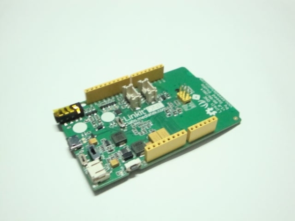
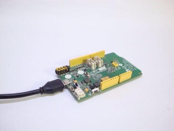
This project is to make a simple RESTful Web service library for IoT Devices. The library is written with C language code and on WIZwiki-W7500ECO platform board from WIZnet. With it, users can implement a RESTful Web service on IoT devices easily. Monitoring IoT devices can be done by RESTful API based on JSON, as well.
WIZwiki-W7500ECO is a compact platform board based on W7500, which is a SOC chip that integrates an ARM Cortex-M0, 128KB Flash memory and hardwired TCP/IP core.
W7500 is the best fit to IoT devices.
A computer for using KEIL uVision5 IDE
These library is developed and compiled with uVision5 IDE.
Step 2: Download, Build and RUN
Download the RESTful Web Server & I/O Control by REST API Project on GitHub repository
‘a’ : P30 pin (digital input / digital output / analog input)
‘b’ : P29 pin (digital input / digital output / analog input)
‘c’ : P28 pin (digital input / digital output / analog input)
‘d’ : P27 pin (digital input / digital output / analog input)
HTTP GET method:Get the device info and IO status / value
http://w7500xRESTAPI.local/index
http://w7500xRESTAPI.local/uptime
http://w7500xRESTAPI.local/netinfo
http://w7500xRESTAPI.local/userio
http://w7500xRESTAPI.local/userio/:id
http://w7500xRESTAPI.local/userio/:id/info
HTTP POST method:Enable the assigned IO
http://w7500xRESTAPI.local/userio/:id
HTTP PUT method* (in development) : Set the IO status (digital output only) and IO configuration
http://w7500xRESTAPI.local/userio/:id
http://w7500xRESTAPI.local/userio/:id/info
HTTP DELETE method:Disable the assigned IO
http://w7500xRESTAPI.local/userio/:id
Step 4: Testing: HTTP Get Method
Connect your board to your network and REST API Testing with test tool. These library has been tested on Postman Builder. For more details about Postman, please refer to Postman Chrome webstore.
I know WIZ550S2E solution for monitoring. Recently WIZwiki-W7500ECO platform was announced by WIZnet. So I implemented a firmware of WIZwiki-W7500ECO by WIZ550S2E SW modification because I can handle a source code easily.
You can know the status of equipment even if it is so far. Please refer to the following step.
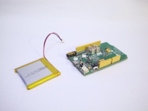
Step 1: Prepare Materials
Please refer to the following. 1. WIZwiki-W7500ECO board. 2. Mini USB cable 3. LAN cable 4. UART2USB adapter
I opened source codes of this project in GitHub. https://github.com/bingdo/S2E_WIZwiki-W7500ECO_Eclipse You can download this project files. And then import project into Eclipse. After compile, you can run S2E application of WIZwiki-W7500ECO. This project is open for everyone. I expect your participation to improve a quality of project.
1. To program FW into a target. 2. To reset a target and insert MAC address. 3. To search a target by Configuration Tool. 4. To check Host IP and Options. 5. To change IP, Gateway properly. 6. To search a target by Configuration Tool again. 7. To select “F/W Uploading”. 8. To change Server IP, File Name properly. 9. To press OK. 10. To check a version of new FW through terminal program. 11. Carry out S2E operation. You can see the test result by the video. Thank you for your attention. *Tip : If you register in www.wiznetian.com and work actively, you can get a sample cheaper than E-sales as well as a free sample.
The circuit what you are about to see is a smart battery charger based on ATMEGA8A with auto cut off.Different parameters are shown via a LCD during different charge states.Also the circuit will make sound via a buzzer upon charge completion.
I built the charger basically to charge my 11.1v/4400maH Li-ion battery.The firmware is basically written to charge this particular battery type.You can upload your own charge protocol to fulfill your needs to charge other battery types.
As u know,smart battery chargers are readily available in the markets.But being an electronic enthusiast,it is always preferable for me to build my own rather than buying one which will have static/unchangeable functions.In this module,i have plans to upgrade in future so i have left space regarding that.
When i first bought my previous 11.1v/2200mah Li-ion battery,i searched for DIY battery chargers with smart control on the internet.But i found very limited resources.So for then,i made a battery charger based on LM317 and it worked really well for me.But as my previous battery died over time(for no reason),i bought another Li-ion battery of 11.1v/4400mah.But this time,the previous setup was inadequate to charge my new battery.To meet my requirement,i did some studying on the net,and was able to design my own smart charger.
I am sharing this as i think that many hobbyist/enthusiasts are out there who are really passionate about working on power electronics & microcontroller and also in a need to build a smart charger of their own.
Let’s take a quick look at how to charge a Li-ion battery.
Step 1: Charge Protocol for a Li-ion Battery
To charge Li-ion battery,certain conditions must be fulfilled.If we don’t maintain the conditions,either the battery will be undercharged or they will be set on fire(if overcharged) or will be permanently damaged.
There is a very good website to know everything necessary about different type of batteries and of course you know the name of the website if you are familiar with working on batteries…Yes,i am talking about batteryuniversity.com.
Here is the link to know the necessary details to charge a Li-ion battery.
If you are lazy enough to read all those theories,then the gist is as follows.
1.Full charge of a 3.7v Li-ion battery is 4.2v.In our case,11.1v Li-ion battery means 3 x 3.7v battery.For full charge,the battery must reach at 12.6v but for safety reason,we will charge it upto 12.5v.
2.When the battery is about to reach it’s full charge,then the current drawn by the battery from the charger drops to as low as 3% of the rated battery capacity.For ex,the battery capacity of my cell-pack is 4400mah.So when the battery will be fully charged,the current drawn by the battery will be reached as nearly 3%-5% of 4400ma i.e between 132 to 220ma.To safely stop the charge,charging will be stopped when the drawn current will go below 190ma(nearly 4% of rated capacity).
3.The total charge process is divided into two main parts 1-Constant current(CC mode), 2-Constant voltage(CV mode).(Also there is topping charge mode,but we will not implement that in our charger as the charger will notify the user upon full charge by alarming,then the battery must be disconnected from the charger)
CC mode –
In CC mode,the charger charges the battery with 0.5c or 1c charge rate.Now what the hell is 0.5c/1c????To be simple,if your battery capacity is for say 4400mah,then in CC mode,0.5c will be 2200ma and 1c will be 4400ma charge current.’c’ stands for charge/discharge rate.Some batteries also support 2c i.e in CC mode,you can set the charge current upto 2xbattery capacity but that is insane!!!!!
But to be safe,i will choose charge current of 1000ma for 4400mah battery i.e 0.22c.In this mode,the charger will monitor the current drawn by the battery independent of the charging voltage.i.e The charger will maintain 1A of charge current by increasing/decreasing the output voltage until the battery charge reaches to 12.4v.
CV mode –
Now as the battery voltage reaches to 12.4v,the charger will maintain 12.6 volt(independent of the current drawn by the battery) at it’s output.Now the charger will stop the charge cycle depending on two things.If the battery voltages crosses 12.5v and also if the charge current drops below 190ma(4% of rated battery capacity as previously explained),then the charge cycle will be stopped and a buzzer will be sounded.
Step 2: Schematic and Explanation
Now lets take a look at the circuit’s working.The schematic is attached in pdf format in the BIN.pdf file.
The input voltage of the circuit can be 19/20v.I have used a old laptop charger to get 19v.
J1 is a terminal connector to connect the circuit to input voltage source.Q1,D2,L1,C9 is forming a buck converter.Now what the hell is that???This is basically a DC to DC step down converter.In this type of converter,u can achieve the desired output voltage by varying the duty cycle.If you want to know more about buck converters,then visit this page.but to be frank,they are totally different from theory.To evaluate proper values of L1 & C9 for my requirements,it took 3 days of trial & error.If you are going to charge different batteries,then it can be possible that these values are going to change.
Q2 is the driver transistor for power mosfet Q1.R1 is a biasing resistor for Q1.We will feed the pwm signal in Q2’s base to control the output voltage.C13 is a decoupling cap.
Now the output is then fed to Q3.A question can be asked that “What is the use of Q3 here??”.The answer is pretty simple,It is acting like a simple switch.Whenever we will measure the voltage of the battery,we will shut off Q3 to disconnect the Charging voltage output from the buck converter.Q4 is the driver for Q3 with a biasing resistor R3.
Note that there is a diode D1 in the path.What the diode is doing here in the path??This answer is also very simple.Whenever the circuit will be disconnected from input power while battery attached at the output,the current from battery will flow in the reverse path via the body diodes of the MOSFET Q3 & Q1 and thus the U1 and U2 will get the battery voltage at their inputs and will power up the circuit from the battery voltage.To avoid this,D1 is used.
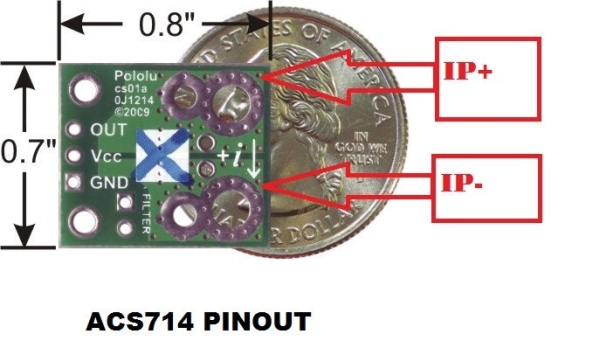
The output of the D1 is then fed to the current sensor input(IP+).This is a hall effect base current sensor i.e the current sensing part and the output part are isolated.The current sensor output(IP-) is then fed to the battery.Here R5,RV1,R6 are forming a voltage divider circuit to measure the battery voltage/output voltage.
The atmega8’s ADC is used here to measure the battery voltage and current.The ADC can measure max of 5v.But we will measure a max of 20v(with some headroom).In order to cut down the voltage to the ADC range,a 4:1 voltage divider is used.The pot(RV1) is used to fine tune/calibration.I will discuss it later.C6 is decoupling cap.
The output of the ACS714 current sensor is also fed to atmega8’s ADC0 pin.Via this ACS714 sensor,we will measure the current.I have a breakout board from pololu of 5A version and works really great.I will talk about in the next stage on how to measure the current.
The LCD is a normal 16×2 lcd.The lcd used here is configured in 4 bit mode as the pin count of atmega8 is limited.RV2 is the brightness adjustment pot for the LCD.
The atmega8 is clocked at 16mhz with a external crystal X1 with two decoupling caps C10/11.The ADC unit of the atmega8 is being powered via the Avcc pin through a 10uH inductor.C7,C8 are decoupling caps connected to Agnd.Place them as closely as possible to the Avcc and Aref correspondingly while making PCB.Notice that the Agnd pin is not shown in the circuit.The Agnd pin will be connected to ground.
I have configured the ADC of the atmega8 to use external Vref i.e we will supply the reference voltage via the Aref pin.The main reason behind this to achieve max possible reading accuracy.The internal 2.56v reference voltage is not so much great in avrs.That’s why i configured it externally.Now here is a thing to notice.The 7805(U2) is supplying only the ACS714 sensor and the Aref pin of atmega8.This is to maintain optimum accuracy.The ACS714 gives a stable 2.5v output voltage when there is no current flow through it.But for say,if the supply voltage of the ACS714 will be lowered(say 4.7v) then the no current output voltage(2.5v) will also gets lowered and it will create inappropriate/erroneous current reading.Also as we are measuring the voltage with respect to Vref,then the reference voltage on Aref must be error free and stable.That’s why we need a stable 5v.
If we would power the ACS714 & Aref from the U1 which is supplying the atmega8 and the lcd,then there would be substanial voltage drop at U1’s output and the ampere and voltage reading would be erroneous.That’s why U2 is used here to eliminate the error by supplying a stable 5v to Aref and ACS714 only.
S1 is pressed to calibrate the voltage reading.S2 is reserved for future use.You can either add/not add this button according to your choice.
Step 3: Functioning…..
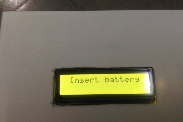
At being powered up,the atmega8 will turn on the buck converter by giving 25% pwm output at the Q2’s base.In turn,Q2 will then drive Q1 and buck converter will be started.Q3 will be driven off to disconnect the buck converter’s output and the battery.The atmega8 then reads the battery voltage via the the resistor divider.If no battery is connected,then the atmega8 shows a message “Insert battery” via 16×2 lcd and waits for the battery.If a battery is then attached,the atmega8 will check the voltage.If the voltage is lower than 9v,then the atmega8 will show “Faulty battery” on the 16×2 lcd.
If a battery with more than 9v found,then the charger will first enter into CC mode and turn on the output mosfet Q3.Charger mode (CC) will be updated to display immediately.If the battery voltage is found more than 12.4v,then the mega8 will immediately leave the CC mode and will enter into CV mode.If the battery voltage is less than 12.4v,then the mega8 will mantain 1A charge current by increasing/decreasing output voltage of the buck converter by varying duty cycle of the pwm.The charge current will be read by the ACS714 current sensor.The buck output voltage,charge current,PWM duty cycle will be periodically updated in the lcd.
.The battery voltage will be checked by turning off Q3 after every 500ms interval.The battery voltage will be immediately updated to the lcd.
If the battery voltage gets more than 12.4 volt during charging,then the mega8 will leave the CC mode and will enter into CV mode.Mode status will be immediately updated to the lcd.
Then the mega8 will maintain the output voltage of 12.6 volt by varying the duty cycle of the buck.Here the battery voltage will be checked after every 1s interval.As soon as the battery voltage will be greater than 12.5v,then it will be checked if the drawn current is below 190ma.If both the conditions are met,then the charge cycle will be stopped by permanently turning off Q3 and a buzzer will be sounded by turning on Q5.Also mega8 will show “Charge complete”via the lcd.
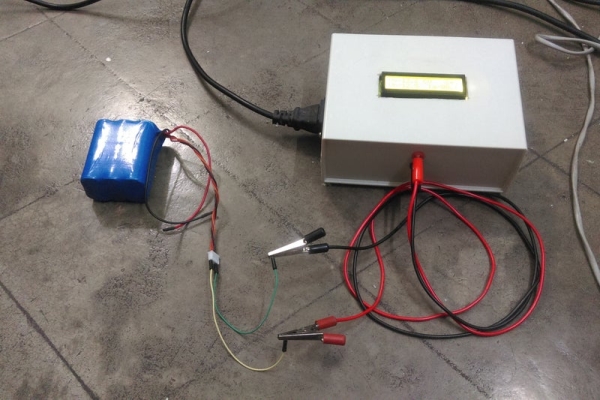
Step 4: Parts Required
Listed below are the required parts to complete the project.Please refer to datasheets for pinout.Only crucial parts datasheet link provided
2) ACS714 5A current sensor from Pololu x 1 (I strongly recommend to use the sensor from Pololu as they are the best accurate among all other sensors i’ve used.You can find it here).Pinout is described in the image.
8) 330uH/2A power inductor x 1 (recommended from coilmaster)
9) 10uH inductor x 1(small)
10) Resistors -(All resistors are 1% MFR type)
150R x 3
680R x 2
1k x 1
2k2 x 1
10k x 2
22k x 1
5k pot x 2(pcb mount type)
11) Capacitors
Note: I didn’t use C4.There is no need to use it if you are using Laptop power supply/Regulated power supply as 19v power source
100uF/25v x 3
470uF/25v x 1
1000uF/25v x 1
100n x 8
22p x 2
12) PCB mount momentary push switch x 2
13) 20v Buzzer x 1
14) 2 pin Terminal block connector x 2
15) Cabinet(I used a cabinet like this.).You can use whatever you like.
16) 19v laptop power supply(I modified a hp laptop power supply,You can use any type power supply as you want.If you want to build one,then visit my this instructables.)
17)Medium sized heat sink for U1 & Q1.You can use this type.Or you can refer to my circuit pictures.But be sure to use heat sink for both of them.
18) Banana connector – Female(Black & Red) x 1 + Male(Black & Red)(depending on your need of connectors)
Step 5: Time to Calculate…… Voltage measurement calculation :
The max voltage,we will measure using the atmega8 adc is 20v.But atmega8’s adc can measure max of 5v.So in order to make20v within 5v range,a 4:1 voltage divider is used here(as 20v/4=5v).So we could implement that by simply using two resistors,but in our case,i’ve added a pot in between two fixed resistors so that we can manually adjust the accuracy by turning the pot.The resolution of the ADC is 10bit i.e the adc will represent the 0v to 5v as 0 to 1023 decimal numbers or 00h to 3FFh.(‘h’ stands for hex numbers).The reference is set to 5v externally via the Aref pin.
So the measured voltage = (adc reading) x (Vref=5v) x (resistor divider factor i.e 4 in this case) / (max adc reading i.e 1023 for 10bit adc).
Suppose we get a adc reading of 512.Then the measured voltage will be –
(512 x 5 x 4) / 1023 = 10v
Current measurement calculation :
The ACS714 will give 2.5v stable output at the out pin when no current will flow from IP+ towards IP-.It will give 185mv/A over the 2.5v i.e for say,if 3A current is flowing through the circuit,the acs714 will give 2.5v+(0.185 x 3)v = 3.055v at it’s out pin.
So the current measurement formula is as follows –
for say,the adc reading is 700,then the measured current will be – (((700 x 5)/1023) – 2.5)/0.185 = 4.98A.
Step 6: The Software The software is coded in Winavr using GCC.I have modularized the code i.e i’ve created different libraries like adc library,lcd library etc.The adc library contains the necessary commands to setup & interaction with the adc.The lcd library contains all the functions to drive the 16×2 lcd.You can also use the lcd_updated _library.c as the start up sequence of the lcd is modified in this library.If you want to use the updated library,then rename it with lcd.c
The main.c file contains the main functions.The charging protocol for li-ion is written here.Please define the ref_volt in the main.c by measuring the output of U2(7805) with a precise multimeter to get accurate readings as the calculations are based on it.
You can simply burn the .hex file directly in your mega8 to bypass the headche.
For those,who want to write another charge protocol,i have put enough comments by which even a child can understand whats going on for each line execution.Just you have to write your own protocol for different battery type.If you are using Li-ion of different voltage,you have to only change the parameters.(Though this is not tested for other li-ion/other battery type.You have to work it out by yourself).
I strongly recommend not to build this circuit,if this is your first project or you are new to microcontroller/power electronics.
I have uploaded each and every file as it’s original format except the Makefile as it is creating problem to open.I have uploaded it in .txt format.Just copy the content and paste it into a new Makefile and build the whole project.Voila….you are ready to burn the hex file.
I’ve always thought it would be nice to have a car with a parking sensor. I don’t want to spend that kind of money until I pay off my student loans. However I do have the materials to make one myself thanks to a class I took on microcontrollers. Part of my motivation is that my car doesn’t make parking particularly easy. The back end is tall and it doesn’t extend out very far so I’m usually too far or too close.
This project will show you how to build your own parking obstacle sensor for your car.
This obstacle sensor shows the distance in inches, cm, or mm depending on the “units” variable you can change in the code. It also displays between 0 to 16 bars in the bottom indicating 0 to 255 inches. The sonar module can only detect between 6 and 255 inches. Any less than 6 will show as 6 and any more than 255 will display as 255.
Test the hardware first to make sure it works and you have the pin selections right. To do this you will need MPIDE. I had used my board with MPLAB X IDE previously so I needed to reinstall the bootloader on the MX4 before I could use it with MPIDE. If you have a fresh board you will not have to do this.
Now download the example project for the PmodCLS LCD screen here. Get the one under MPIDE and follow the README contained within. Open the example project CLSDemo under CLS and upload it to the board. If all the jumpers are in the right places the program will run and show the screen you can see in the first picture.
note: If you get the error indicating you need Bounce.h get it from here and add it to your libraries.
To run the example project for the MAXSonar module on an MX4 you’ll need to change a few pin definitions in the program.
#define ANpin 48
#define RXpin 49
#define PWpin 50
Get the example installed and change the pins to the following and plug the sonar module into the top row of JH. If you upload your revised example project and open the Serial Monitor window in MPIDE you should see the same output as you see in the Serial Monitor.
With that taken care of we can put the obstacle sensor together and program it.
Step 3: Hardware Layout
I wanted this project to be as portable as I could make it given the size of the MX4. The screw holes on the LCD line up perfectly with the left or right screw holes on the MX4 so I decided to screw it to the top using standoffs. They were a touch too short so I added washers on the top and bottom of the standoffs as you can see in picture 2.
To stop the LCD cable sticking out the side bend the Pmod Header pins around. Use a pair of pliers to bend all of the pins up. It doesn’t take very long.
The battery will be attached to the back using velcro in a later step.
Step 4: Software
Download the MyRangeDisplay folder and open MyRangeDisplay.pde with MPIDE. Upload this to your MX4 board and it should display the distance from the sonar module to the nearest detectable obstacle. I only have one sensor displaying on the screen but when I get another one I will modify it to show both on the same screen. It might be more cramped on the display but it will help when backing towards something at an angle.
The most up to date version of this program will be on my GitHub here. I know I’ll have to tweak the program to make it more to my liking.
I should stress I am not connected with Picaxe and these projects are ones I used in School to teach programming to school kids.
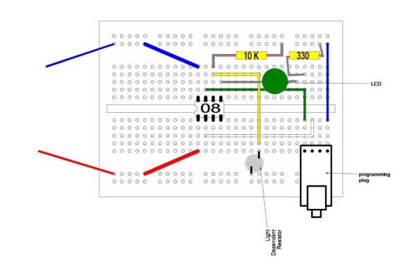
In the last instructable the circuit was built on breadboard which is very useful for experimentation. We will use that breadboard again for these experiments.
This time I am going to look at using some inputs and how they can be made to activate outputs.
As before all the components can be found at the Picaxe shop
then you will already have the 08M2 chip and the programming adapter mounted on the breadboard.
Because the breadboard is getting a little crowded I have drawn the connections above rather than photographing the actual board.
You can see that the LDR (Light Dependent resistor) is connected to + volts on one side and to the Picax leg 6 on the other side.
The LDR has no polarity so it will not matter which way it is inserted.
To make the Picaxe microprocessor register the value of the LDR it needs a 10K resistor from leg 6 to the 5 volts supply. This forms a potential divider.
To free up Leg 6 the LED has been moved to Leg 5 which is programming pin 2.
Step 2: Analogue Interface
ADC
Computers work in a digital manner, that is they understand two states, On and OFF, because these are easy to detect.
However the real world works in an analogue manner, that is things may have a wide range of values. The volume of Sound can vary from quite to loud, the intensity of Light can vary from dark to bright light.
We need a way to convert the analogue real world into the digital computer world.
A Picaxe input is usually a digital input, it is either on or off but Picaxe chips have some of their inputs that can be used to convert varying analogue values into a digital number. generally there are 2 types of conversion, the first measures the analogue input and converts it into a scale of 0 to 255.
The second measures the analogue input and converts it to a scale of 0 to 65535 and is therefor more accurate – BUT it needs more storage space in memory so unless you need this accuracy it is best to use the simpler form.
This conversion is called Analogue to Digital conversion (ADC)
Storing Numbers
Before we get to the read command lets consider how the Picaxe stores its numbers.
Number in the computing world are Binary, that is either 1 or 0. This matters not and we can still count using Binary.
Binary Decimal
0 0
1 1
10 2
11 3
100 4
101 5
110 6
111 7
1000 8
Each Binary digit is called a BIT
A group of 8 bits is called a BYTE (I am sure you have all heard of mega Bytes and Giga Bites)
A group of 16 Bits is called a word Although the length of a word can vary with different computer types, there may be 16 bits in a word or even 34 or 64 bits in a word on large mainframe computers. the longer the computer word is the more data you get every time a word is called up, a longer word can also handle bigger numbers.
In the Picaxe numbers are stored in variables, each variable has a label so it can be identified. For the Picaxe 08M2 chip there are 28 of these general purpose variables labeled B0 to B27 – Each variable can store a number up to a maximum of 255.
This is a byte variable. It is possible to deal with larger numbers but we don’t need to consider that at present. See Picaxe manuals if you need to know.
So we can store numbers in variables Now we can do some maths with the values:-
B1= 15 will put the number 15 into memory labeled as B1
B2= 20 will put the number 20 into memory labeled as B2
B3=B1+B2 will put the number 35 into variable B3
we can read analogue values from external sensors and put that value into a variable.
So the command to read and convert an analogue value is
Readadc pin – the pin is where you are reading the value from
In our case we are using pin C.1 as the analogue input
Step 3: The Program.
Of course having assembled the hard ware we need to code the program to bring it all together.
So far we know the commands High, Low, Wait and goto
We are going to introduce the command that is used to test an input or to test the content of a variable..
This command is in the form of a statement – IF an input = something THEN jump tothis label.
In basic called an IF..Then command.
We also need to use the readadc command to fetch and convert the value seen at pin C.1 this command needs to know where to store the value it reads so we tell it put it in variable b1.
The command line is Readadc c.1,b1
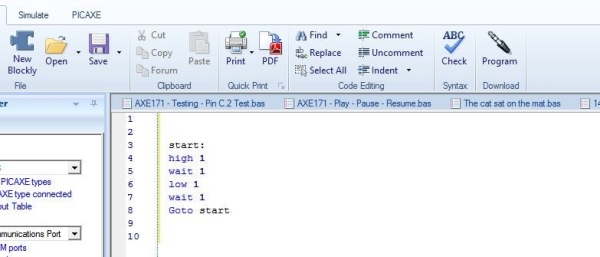
In the program below we first set a label at the beginning called main:
We the do the readadc command to get the value at the LDR cell.
we put that value in variable b1.
We then check that value with the IF …then command and IF the value is greater than 50 we jump to a part of the program that will turn on an LED connected to pin c.2.
We now have a different command to wait for a time. Wait is in whole seconds whilst the PAUSE command is in 1/1000 of a second so pause 500 is half a second.
After half a second has passed we turn the LED off and go back to the main label to do the operation over again.
if the IF … THEN test isn’t true i.e the value in B1 is below 50 then we do not go to the flash routine but drop to th next command which says goto the label main to start again.
main: Readadc C.1,b1 ; read value into b1
If b1 > 50 then flsh ; jump to flsh if b1 > 50
Goto main ; else loop back to start
flsh: high c.2 ; switch on output C.2
Pause 500 ; wait .5 seconds
Low c.2 ; switch off output C.2
Goto main ; loop back to start
Input the program into the editor as before and download to the Picaxe 08M2 chip.
In normal room light the LED should be flashing
If you cover the LDR or turn the room light off the LED should be OFF.
With slight modification to the code this could be an alarm to show if anyone turns the lights on or moves sometime to uncover the LDR.
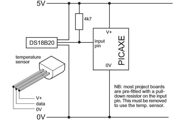
Step 4: Measuring Temperature Accuratly
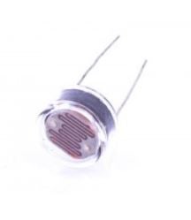
If you want to use the Picaxe to measure temperatures accurately (-55 deg C to +125 deg C) then your best bet is to buy a DS 18B20. This is a small IC – looking like a 3 wire transistor which is dedicated to measuring temperature.
This is so useful the Picaxe has a special command to read the output from this sensor.
READTEMP Pin, variable.
You need to connect the DS18B20 as in the diagrams above ensuring you have a 4K7 pull up resistor on the data line to make it read correctly.
The program is simple:
Main:
Readtemp C.1,B1
Debug B1
Goto main.
The Value in B1 is the current temp of the chip rounded to the nearest whole deg C
The DEBUG command will request the value in B1 and send it to the PC via the download cable, a window will open on the right side of the screen and the debug values of all the variables can be seen in that window.
Step 5: You Now Know, and Other Things to Do
You now have available commands:
High = Turn an output ON
Low = turn an output OFF
Wait = Do nothing for the specified number of seconds
If…Then = Check an input or a value to see what to do.
Pause = Wait for a shorter amount of time in 1/1000 of a second
Readadc = Read an analogue value and convert to digital and store in a variable.
DEBUG = Sends the value in one or several variables to the PC screen via the programming cable.
These commands can be combined to make a simple robot work and avoid obstacles (a later project).
They can make a model car park barrier operate
They can pretty much do most of the simple things you might want to do so they are very powerful.
Replace the LDR with a Thermistor and you have a system that reacts to temperature.
Using the materials you have if you have followed this so far you could:
Make a burglar alarm.
Make a night light
Make a night light that turns off after a set time
Make An automatic system to illuminate your alarm clock, the hall, the stairs, your den when it gets dark.
In this Instructable I will let you know the basic building block of a Quadcopter and how to make it in a very simple way.Only thing you need is some skill on Soldering and few basic tools.I think it will give opportunity to the new hobbyists to sharpen their skills on this platform.
To demonstrate the process I choose Hubsan X4 -H107.Because its parts are very cheap, easily available,huge community resources in the internet.For a beginner I think it is one of the best Quadcopter to get started.
Note : If you already have a HUBSAN X4 then this guide will be helpful to repair it after a fatal crush.Just follow the steps in the reverse order.
What is a Quadcopter :
A Quadcopter is a type of helicopter with four ( Quad ) rotors, so it is known as Quadrotor. Because of its unique design, it allows a more stable platform, making it ideal for surveillance and aerial photography. A normal helicopter has one big motor to provide all the lifting power but a Quadrotor has four motors all work together to produce upward thrust and each motor lifts only one fourth of the total weight. The Quadcopter’s movement is controlled by varying the relative speed of each motor.
How it is Work :
A Quadcopter depends on the flight controller and Electronics Speed Controller (ECS) to distribute the correct speed to each of the 4 motors depending on what we want it to do.I found a great article on basics of Quadcopter on Learn Robotix blog. You can go through it to get more clear ideas.I am attaching the links below
To control the Quadcopter and make the entire structure stable in air,it needs an electronic system which is called Flight Controller.It is the brain of the Quadcopter and uses gyros to keep the aircraft stable.
The Hubsan X4 Receiver Module ( Flight Controller Board ) has gyroscope, accelerometer, and radio receiver all placed onto a single PCB board to minimize space requirements and complexity.Another good thing is that all the soldering pads on the board are named neatly. So you can solder the motors and LEDs very easily.
LEDs are very helpful during the night flying.There are 6 LEDs on Hubsan-X4 ,two on board and remaining fours are to be installed in each arm (near the motors). There are two pairs of LEDs i.e RED and BLUE.We have to installed the Blue pairs on the front and Red pair on the back side of the Quadcopter.
The LEDs have a red positive leads and a yellow/bronze negative lead.You can identify the colour by closer inspection, it looks like the heat shrink on the positive lead matches the LED colour.
Insert the wires of the LEDs in to the slots given in the each arm end.
Use a tweezers to thread the LED wires in to the leg slots.
Before going to solder,check it by using a coin cell.You may do this earlier also.I have found one of my red LED was damaged during shipping.
Then Solder the LEDs to the Flight controller.You can see soldering pads on the board are named neatly ( LED3, LED4 , LED5 and LED6 )
Step 4: Mount the Motors
The motors with the help of propellers provide lift and direction to the Quadcopter. They are controlled by Electronics Speed Controller.The Hubsan X4 Controller circuit board has a neat design where it´s almost impossible to connect wrong motor to wrong connections.There are two different type of motors clockwise (CW) and counter clockwise (CCW).The motors come with different coloured wire to identify it easily.
Clockwise — Black and White Wire
Counter Clock Wise — Red and Blue
Insert the wire and press the motor from top side to fix it.
Use a tweezers to thread the motors wires in to the arms.Put it just above the LEDs wires.
Then trim the extra wires by the wire cutter.
Solder the wires to the corresponding solder pads ( M1,M2,M3 and M4 )
Note : 1. The diagonal motors are of same type. 2. Black and Blue wires are negative.
Step 5: Install the Propellers
The propellers are mounted on each of the motors to provide the required thrust.
The 4 propellers are actually not identical. On closer look you can see that the propellers are tilted in different direction.By making the propeller pairs spin in each direction, but also having opposite tilting, all of them will provide lifting thrust without spinning in the same direction. This makes it possible for the Quadcopter to stabilize the yaw rotation, which is the rotation around itself.
There are two pairs of propeller.They comes with variety of colours. I ordered the black and green pairs.
On closer look you can see they are named like ” A” and ” B”.
Insert the black pairs in to the front side motors shaft.
Then insert the green pairs in to the back side motors shaft.Remember the diagonal blades are of same name.
i.e On a particular diagonal one Green A blade and another black A blade.
Step 6: Fix the Rubber Feet
Rubber feet are used to absorb the shocks from the 4 landing gears during the landing.It prevents the motors and the Quadcopter from severe shocks during crushing or falling from a height.
Slightly open the rubber slots and fix it to the each landing gear bottom projection.
Step 7: Close the Lower Shell
The lower shell have two parts the shell itself and the battery compartment.
First put the battery compartment in to the lower shell.
Fix it to the upper shell.The screw holes should be aligned.
Tighten the 2 screws on each side.
Finally apply pressure downwards on each arm to snap the lower body.
Step 8: Insert the Battery
LiPo batteries are used to provide power to the Quadcopter.
You can never have enough batteries when it comes to flying your Hubsan X4! With a flight time of just 5 to 8 minutes on a full charge, it is imperative that you own at least a couple of spare batteries to be able to continue flying your drone without any stopping. And if you are close to a charging source, then you can have you non-stop playtime!
Insert the battery in to the bottom battery compartment .
Twist the wires and squeeze them in to the notched holder as shown in above pics.
Make sure the battery and wires are pushed in to the end of battery compartment, so they will not negatively affect the centre of gravity and cause unstable flight.
LinkIt ONE comes with audio output through onboard audio jack. For size and power considerations we use a notebook spare part micro speaker with an audio amplifier breakout. The steps are:
1. Connect LinkIt ONE audio jack to the audio plug to the input pins of audio amplifier breakout with jumper wire, soldering may required on the audio plug.
2. Connect 3.3V and GND on LinkIt ONE to audio amplifier breakout for powering the amplifier.
3. Connect the micro speaker to the output pins of audio amplifier breakout with proper connectors, here we soldered a JST 2-pin cable on the speaker, and use a JST-PH 2-Pin SMT Right Angle Breakout Board in between.
4. Google and download sound clip file of your favorite robot, you may need convert file format with some free online audio file format converter.
5. Set the switch beside the micro USB of LinkIt ONE to “MS”, connect LinkIt ONE to your computer with USB, LinkIt ONE will appear as a removable device. Copy the sound clip file to LinkIt ONE with proper filename and file extension.
6. Disconnect LinkIt ONE from your computer and set the switch beside the micro USB of LinkIt ONE back to “UART”.
7. Connect LinkIt ONE to your computer and run Arduino IDE, set the Tools->Board to LinkIt ONE, and set proper Port. Open File->Examples->LAudio->AudioPlayer.
8. Copy the line containing LAudio.playFile command to first line inside void loop() function, change the proper file name, and add delay(5000); after the playFile command.
9. Compile and upload code see if the sound clip is playing from the speaker.
Step 3: Adding Sense
LinkIt ONE comes with various GPIO, for wiring simplicity we use a VL6180X Time-of-Flight Distance Sensor Carrier with Voltage Regulator via I2C. The steps are:
1. Connect the 5V and GND of LinkIt ONE to VL6180X.
2. Connect the SDA and SCL of LinkIt ONE to VL6180X.
3. the reading of VL6180X will vary from 10~255 for a max distance about 20cm.
4. goto https://github.com/pololu/vl6180x-arduino/ setting up the required library.
Step 4: Putting Together
1. Download the attached linkitone-walle.ino, compile and upload to LinkIt ONE.
2. Connect battery to LinkIt ONE.
3. Attach everything to your robot.
4. Turn on LinkIt One and enjoy!
5. Adding more I2C sensors, audio clips, and more programming to make it more fun!
This simple DC motor controller allows for one direction motor control and has been built entirely of reclaimed electrical parts. Using MOSFET’s for motor control instead of control chips, allows for an external power supply and electric isolation of the motor and control board. Which allows for the use of higher voltage and amperage motors than the micro-controller can support.
For this project you will need:
– A DC motor (I used a salvaged DC fan)
– MOSFET (I used a 110v 30amp make sure it is rated for more than your fan)
– Solder less bread board
– Jumper Wires
– LinkIt One (or another micro-controller)
– (volt battery and connector)
A huge thank you to instructables, autodesk, MediaTek, and Penolopy Bulnick for sending me the Link It One used in this instructable.
Check Out Our Other Accounts! Like, Subscribe, and Follow to keep up to date with our latest projects. 🙂
Step 1: DC Motors
DC motors work by changing the polarity of electromagnets in the stator around a circular pattern causing the shaft to rotate. They are able to rotate in either direction at high rates of speed, but do not have a high degree of accuracy of their motion.
Step 2: Wiring of Control System
First place the MOSFET onto the bread board, then connect the battery connector to the power rails. Place a jumper wire from the hot power rail to one side of the MOSFET gate, and a second jumper wire on the other gate to connect the motor. Place a data wire from the control pin to one of the PWM digital pins (i.e. Pin 9).
Step 3: Attach the Motor
I used electrical merits to connect the motor to the leads from the battery connector and MOSFET. This way the polarity can be switched depending on which way you would like the motor to turn.
Step 4: Coding
To control the speed of the motor set pin 9 to be an output and send a value between 0-255 to the MOSFET.
0 is no movement and 225 is full speed.
If you have any suggestions for improvement, questions, or photos of you own projects make sure to comment below. Have a great day! 🙂
This DC Motor Multiplexer allows you to control up to four DC motors in forward and reverse using one MOSFET and only 5 digital pins.
For this intractable you will require:
– DC motors (I used salvaged DC fans) – MOSFET (I used a 110v 30amp make sure it is rated for more than your combined fans)
– Solder less bread board
– Jumper Wires
– LinkIt One (or another micro-controller)
– 9volt battery and connector
– 8 relays
A huge thank you to instructables, autodesk, MediaTek, and Penolopy Bulnick for sending me the Link It One used in this instructable.
Check Out Our Other Accounts! Like, Subscribe, and Follow to keep up to date with our latest projects. 🙂
Step 1: Controller
First place the MOSFET onto the bread board, then connect the battery connector to the power rails. Place a jumper wire from the hot power rail to one side of the MOSFET gate, and a second jumper wire on the other gate to connect the motor. Place a data wire from the control pin to one of the PWM digital pins (i.e. Pin 9).
Step 2: Relays
From each relay control pin split the jumper wire into two jumper wires and use them to control each pair of side by side relays. The first relay of each pair will be positive, and the second relay will be neutral. Then the left contact of the relay pair will be for one direction and the right for the opposite direction of control.
NOTE: This multiplexer can control all four motors simultaneously, but can only have a single power setting, but the direction can be reversed.
This setup would work perfectly for a Skid Steer robot design or for a system which only requires the movement of one motor or a pair of motors at a time.
Step 3: Coding
To control the speed of the motor set pin 9 to be an output and send a value between 0-255 to the MOSFET.
0 is no movement and 225 is full speed.
The digital pins used to control the pairs of relays must be set as outputs. When nothing is being set to a pair of relays they will turn the motor in the native direction of the relay (marked by the solid line), and will reverse the motor when a HIGH signal is sent.
If you have any suggestions for improvement, questions, or photos of you own projects make sure to comment below. Have a great day! 🙂
In this instructable I’m going to show you how to design a kitchen timer using the Linkit One, the timer has a maximum duration of 30 minutes. And once the timer is done counting down it fires a buzzer to notify you. The time interval can be set in steps of 5 minutes and each led indicating 5 minutes. You can also increase the maximum duration by adding extra LEDs and go up to a maximum of 50 minutes due to the limited number of pins on the Linkit one.
Step 1: Tools and Components
All the components you require for this instructable are –
Linkit One
6 Leds
Push Button
Buzzer
Jumper wires
Breadboard
10k resistor
Step 2: Circuit
The circuit is quite simple and all you need to do is follow the picture above. There are six LEDs and each LED indicates a 5 minute interval. By adding additional LEDs to the remaining digital pins you can improve the maximum duration of the timer circuit.
Step 3: Code
Copy the below code and paste the below code in the Arduino IDE and then select a suitable COM port and upload the code to the Linkit One.
After uploading the code find a place to set it up in your kitchen and when its time to cook you can click the button multiple times to set the time duration. Each click represents 5 minutes (1 click = 5 minutes, 2 clicks = 10 minutes).
In this instructable I’m going to how you how to measure the temperature using a Linkit One and a Lm35 temperature sensor. This project can be a part of a wireless weather monitor, if you have not seen my previous instructables please check it out, I have a lot of other Linkit One tutorials.
Step 1: Components
Here is a list of all the components required to get started, make sure you collect all the components first before proceeding to other steps-
LM35
Wires
Bread Board
Step 2: Schematics
The schematics can be found in the picture above, I had to use an arduino to represent the linkit one as Fritzing doesn’t have a library for the Linkit one yet.
Step 3: Program
To upload the program you need to install the Linkit one plugin along with the Arduino IDE. You can find instructions on how to do that in the official website. You can also download the IDE with the Linkit One plugin pre-installed from GitHub.
After uploading the code you can set up the circuit at the place where you want to monitor the temperature, then connect the Linkit One to a PC and open up a serial monitor. You should see the temperature data on the serial monitor.
These days in families, both men and women have started working. Both men and women want to succeed in life and for this they have to work hard and spent more time in the offices. Due to this it becomes difficult for both of them to look after their children. Due to pressure of they offices many of the parents are not able to call their children and as them weather they have reached the house from school or from any other place safely or not. If you come in the category of those parents then I will help you to reduce your tension. This project consist of mediatek linkit one as the controller. A simple push button is attached to this project. Keep it near you door so that when your children enter the house they remember to push this push button. When they will push the button, a SMS will be send to your mobile number and the appliance attached to this project will be turned on. For example when your children will enter the house, they will search for switch board to turn on light. When they will push the button to turn on the light, a SMS will be sent to you telling that your children have reached the home safely. I am sure that this will reduce your stress. Don’t forget that you have to change the message in the code from your message which you want to receive when your children reach home. You can also use it to notify yourself when you life partner reaches home. This is a simple step taken by me to reduce the stress of various parents.
Step 1: Collect Parts
Here are the parts required by you to make this project. There I have used some module which you may not have but their is no need to worry because they are basic modules which you can make by yourself. I further steps I will be telling you how to make those modules. Here is the list:
Linkit one
Relay module
Push button module
A SIM card
Linkit one GSM antenna
Linkit one battery
Jump cables(male to female are preferred)
A box or enclosure
A USB cable to upload the code
Step 2: Connect the Battery
This is the first and the most basic step. Your linkit one board already comes with a 3.7V 1050mah li-ion battery. Just pick up that battery and insert the plug of the battery into the plug present on your linkit one board in left side. It will go inside only one way. To check your battery status or power level of your battery go in examples folder of your arduino ide and upload “LBattery” code to your board and open the serial monitor. Your battery level would be displayed there.
Step 3: Insert the SIM
When the switch is pressed a SMS is also send to the registered mobile number. These days SMS can be sent through internet but the better option would be to use a network provider to send the SMS. For that you would be needing a Mini size SIM card. Make sure that you buy mini size SIM card as linkit one does not support micro or nano size SIM card. Insert the SIM card to the SIM slot present at the back side of the board. Make sure that you insert it the right way.
Step 4: Connecting the GSM Antenna
Linkit one comes with three different types of antennas. One is for GPS, one for WiFi and Bluetooth and one for GSM. Since we are using only GSM feature of linkit one in this project, you would be needing only one antenna. The GSM antenna is rectangle in shape(the big one). Take that antenna and find GSM port one the downward side of linkit one. Connect that antenna to that port(you may have to apply some force while connecting) and you are done.
Step 5: Connectig the Push Button Module
A push button module is a small module consisting of a push button and a resistor. If you don’t have a push button module you can make one for you on a small PCB. You only need a push button, small piece of PCB and a 10K resistor. Connect vcc of push button module to linkit one 5V,gnd to gnd and Vout to digital pin 8. If you are making a module, then connect one pin of push button to linkit one vcc, other pin to digital pin 8 and short digital pin 8 to gnd with a 10K resistor.
Step 6: Connecting the Relay Module
In the final product, when the push button is pushed, it will send an SMS as well as turn on the appliance connected to it. The appliance can not be connected directly to the linkit one board as the voltage output of linkit one is 3.7V whereas most of the appliance require 110V to 220V to work so we would be needing a relay which can switch the voltage of you linkit one from a 110V to 220V supply. For switching you can use a relay module like me or can make a module of your own by the circuit diagram attached in the images given above. Connect the vcc of the module to linkit one 5V , gnd of the module to linkit one gnd and Vout of the module to digital pin 11.
Step 7: Making an Enclosure
Choosing a correct enclosure is a important thing. You would be needing a enclosure of small size in which all your things can fit. Don’t choose a enclosure in which you can not drill holes properly. Take a enclosure which is small in size, not too much thick, rigid, durable, with thin walls etc. After choosing the enclosure, drill two holes in it. One from which the hump cables of push buttons can pass and other from which the wire going to your appliance can pass. If forgot to tell you that your push button module would be outside your box whereas all other things are inside it. Place all the things inside the box and close it and proceed to next step.
Step 8: Upload the Code
Here is the code you need to upload to your board. Make sure that in the code you change the number “1234567890” from your mobile number and change the message from your message. After uploading the code proceed to next step where you would be told how to use it. Here is the code:
#include <LGSM.h>

int push=8;

int relay=11;
int state=0;

void setup()

{

Serial.begin(9600);

while (!LSMS.ready())
delay(1000);

Serial.println("SIM ready for use");

pinMode(8,INPUT);

pinMode(11,OUTPUT);

}

void loop()

{
LSMS.beginSMS("1234567890");
if(digitalWrite(push)==HIGH && state==0)

{
sentLSMS.print("I am here");  // please change this line for your message
state=1;
digitalWrite(push,HIGH);
}
else
if(digitalWrite(push)==HIGH && state==1)
{
digitalWrite(push,LOW);
state=0;
}
}
<br><br>
Step 9: TEST
Now its time to test your project. Power on your board and leave it for about 10 seconds so that your SIM card can connect to your telecom partner. The push the button kept on the top. After pushing, the appliance connected to your board will be switched on and you will receive a SMS. When you will again push the button, the appliance you be turned off but this time you will not receive the SMS. S now your project is ready to be used.
Step 10: The End
Place this project at you main door or outside your door. When you reach your home, by simply pushing the button you can give them a message that you have reached the home succesfully thus reducing their tension Hope you like the project and loved it. For any query and problem comment below. Your can change the project according to your use. Do remember to post your project photos also. THANK YOU
These days theft has become a serious crime. People are now much more conscious towards there precious items are purses and jewellery but due to the busy routine of this life we are not able to take care of our things. That constant detraction of threat is a great problem. But don’t worry, I am here to save your object from threats and from various treachery.This project will help you to locate you valuable items and thing when they are stolen. It will send you the gps location of your items through SMS. When this project tracks any activity in the item or thing inside which it is kept, it sends an SMS to the mobile number registered to it. I made this project after my backpack was stole and didn’t want my other items to be taken away by thieves. You can place it in the jewellery compartment of your Almira to save your jewellery. I think this project will surely help you in your daily life.
Step 1: Collect Part
You don’t need a lot of things for this project. The only extra part you need to order is a mercury tilt module. Rest are the basic parts which I think you have and some parts already comes with Linkit one. Here is the list:
Linkit one
Battery for linkit one
GSM antenna
GPS antenna
Mercury tilt switch
Jump cables(I advise you to female to male)
A box or container
Soldering iron
A USB cable
A SIM card
Step 2: Connect the Battery
This is the first and the most basic step. Your linkit one board already comes with a 3.7V 1050mah li-ion battery. Just pick up that battery and insert the plug of the battery into the plug present on your linkit one board in left side. It will go inside only one way. To check your battery status go in examples folder of your arduino ide and upload battery status code to your board.
Step 3: Connecting the Antennas
When any motion in your package or the object in which this project would be kept is detected, a SMS notification will be send to the registered mobile number telling that their is some motion detected in this package and the GPS co-ordinates of your package would be send on your number. You don’t need a external GPS or GSM shield for this project as Linkit one already have those two modules. To make these modules work more efficiently, you need to connected the specific antenna to that specific port. The antenna are also included in the linkit one package. Just take out the gps antenna(a square shaped antenna)and GSM antenna(rectangular shaped antenna,big one). Connect them to their specific port. The name of every port is written under it. Now are are ready with your antennas.
Step 4: Inserting the SIM Card
When their is any activity sensed in you package or thing a SMS notification is sent to the registered mobile number that any activity is sensed in your package and you will get its GPS co-ordinates of it. To send this notification you would be needing a network provider like a SIM card.Make sure that the SIM card you have is a full sized SIM card. Other sim card does not work in linkit one. I advise you not to use SIM card converter. Insert you SIM card in the SIM card slot of your board and make sure that the SIM card is inserted properly and in the right way. You SIM card should not be pin locked.
Step 5: Connect the Tilt Switch
The tilt switch I am using in this project is a mercury switch tilt sensor. Their is a bulb like structure attached to the PCB in which mercury is filled. Inside the bulb are present two small metal rods and a drop of mercury. Mercury being liquid at room temperature (moves inside the bulb because it is a liquid) and a metal (so it conducts electricity) short both the rods when the module is tilted. By this mercury we are able to sense the tilt. Connect the vcc of the module to linkit one 5V, gnd to gnd and Vout to digital pin 8.
Step 6: Selecting an Enclouser
You would be needing an enclouser or box of adequate size in which you can keep your various things like linit one board, battery, tilt sensor. Choose a box in which all your things fit easily. To choose a box which is very big in size. Choose a box which is handy and portable. Also remember that to take a box which is too thick. This could decrease the network coverage of your SIM card. The material od the box depends on you.
Step 7: Upload the Code
Here is the code needed by you which you need to upload to your linkit one board only. Make sure that in the below code you change the number “1234567890” from your mobile number. Here is the code:
void printGPGGA(const char* str)<br>{
char latitude[20];
char longitude[20];
char buf[20];
const char* p = str;
p = nextToken(p, 0); // GGA
p = nextToken(p, 0); // Time
p = nextToken(p, latitude); // Latitude
p = nextToken(p, 0); // N
p = nextToken(p, longitude); // Longitude
p = nextToken(p, 0); // E
p = nextToken(p, buf); // fix quality
if(buf[0] == '1')
{
// GPS fix
p = nextToken(p, buf); // number of satellites
Serial.print("GPS is fixed:");
Serial.print(atoi(buf));
Serial.println(" satellite(s) found!");
Serial.print("Latitude:");
Serial.println(latitude);
Serial.print("Longitude:");
Serial.println(longitude);
LSMS.write("GPS is fixed:");
LSMS.write("Latitude:");
LSMS.write(latitude);
LSMS.write("Longitude:");
LSMS.write(longitude);
LSMS.endSMS();
}
else
{
Serial.println("GPS is not fixed yet.");
}
}
int state=0;

int sensor=8;

void setup()

{
Serial.begin(9600);<br>while(!LSMS.ready())
delay(1000);
Serial.println("SIM ready for work!");
LSMS.beginSMS("0123456789"); // replace the no. to the receiver's no.
LGPS.powerOn();
Serial.println("GPS ready for work!");

pinMode(sensor,INPUT);

}

void loop()

{
Now you can test your project. After changing the number is the code and uploading the code to your board your project is ready. Power on the battery and after few seconds tilt you project so that tilt sensor is activated. You would receive a message telling you the gps co-ordinates of your project,
Step 9: END
This is the end of this instructable. Hope you like it and loved it too. For any query relating the project or you want to ask any question, comment below . Thank you.
Interactive TV is a tamil channel, Where we lot of programs and also interactive games by call the number and use the mobile button to play the game on the television. Want to do some thing like that for local cable TV for my friend.
So using DTMF to catch the keypress and play the game in local pc in the cable tv station and that pc display is link with the cable tv telecast is the plan. Its very funny to learn some thing new like this.
Step 1: Materials Required
1) Linkit one board with GSM antenna.
2) Mobile sim card with good network coverage.
3) DTMF(Dual-Tone Multi-Frequency).
4) Male and female jumper wires.
5) Audio jack to connect Linkit one with DTMF decoder.
6) 5 Wire strip with one side male and other side female connector.
7) Linkit one usb cable.
Step 2: GSM Network
To connect the linkit one to GSM network. Insert a sim card with no lock in the sim card slot on the back of the Linkit one board. Only no lock sim must be used. Use a network with full coverage to clarity.
Step 3: Step by Step Connection
No need for soldering is a major plus point so any one can do it.
1) Connect audio jack to the Linkit one board.
2) From the audio jack take two wires one from audio jack to speaker GND and another audio jack to speaker positive.
3) connect the GND to DTMF decoder GMD pin and positive to DTMF pin in the board.
4) DTMF need 5v power supply. Use jumper wiresto connect 5v and Gnd power supply from linkit one to DTMF decoder board.
5) Put this arrangement in a box. Paste the wires peeping out over the box to the bottom of the box.
6) Connect the 5 strip wire female connector to VT, D4, D3, D2, D1 pins.
7) Connect the other end of the 5 trip wire male connector to the Linkit one digital pins D12, D11, D10, D9, D8 pins.
8) Connect the Linkit one usb cable.
Its all finish very simple work no need for solder and more fun.
Step 4: Selecting Game
Selecting the game is very important. If u have flash developer then u can create urself simple games. Keep in mind while selecting the game.
1) Don’t select any game which want continuous key press.
2) Dont select multikey same time function games.
3) Select 2 to 3 button games.
4) Don’t use flash games because send keys never work in flash games.
Game i select now
1) I selected a Snake game so i use keys 2,4,6,8 for 4 directions.
Step 5: Microcontroller Program
1) Use LGSM library for mobile receiving coding.
2) In program running loop getvoicecallstatus. Waiting for call from mobile.
3) When Receiving call status is received answer the call command given.
4) Now the audio received pass to the DTMF decoder through the audio jack.
5) From the DTMF board VT pin high low when new DTMF code received.
6) So after new code receive read the data pins.
7) So it is a binau code of 0001,0010 like wise.
8) convert it to decimal and send to pc through serial communication.
9) Like wise while new call receive or current call close send the detail to pc through serial communication.
Step 6: VB Program and Running
Program
1) Use VB program to control the game.
2) When the connection is made the program minimize to task bar to let the next active application to come front.
3) In VB program use MSComm control to receive data from Linkit one board.
4) Use the send keys command to create virtual key down event.
5) That keys stokes play the game.
6) according to the game selected the program varies.
Running
1) Open the game go up to start.
2) Next Open the Play game exe.
3) Find the linkit one com port on the device manager of the computer.
4) Type the comport number on the text box. Click the play game button.
5) Now the form minimize to the task bar and the game on the active application.
6) So when call receive as per send keys the game start.
7) When press the keys the game run.
8) When stop the game play the link between the PC and micro controller will break.
I decided to use the Linkit One’s GSM capabilities to create a weather indicator. This would allow me to make something both practical and visually pleasing, a wireless weather indicator.
Step 1: Materials/Tools
Tools
Soldering Iron
Computer
Linkit One
GSM anntenna
Battery for Linkit One
USB cord
Wire Cutter
Materials
RGB LED
White LED
Solder
Poly-Fil
Container – Should be transparent so you can see the lights from the indicator.
SD card
Ballast – I had a round contatnier and used pennies to balance it.
Battery for Linkit One
GSM antenna
Speaker
Step 2: Code
The code went through several very different versions before it was finished. I tried utilizing the wunderground api at first but them abandoned it. I decided to use the Linkit One’s SMS capabilities to read the weather update text alerts from wunderground. I had to set up the code to read the text and pull out the relevant text dealing with the current weather conditions. I had to set it up to look for the specific abbreviated phrases that the text alerts use. For example if conditions are clear then the text will use the abbreviation clr. I have tried to gather all the abbreviations, but have not been able to find it documented anywhere so at the moment I am using the weather conditions I am aware of. As I get more updates I will update the code.
Here are the abbreviations I know about;
Clear – Clr
Thunderstorms – T-storms, Chnc T-storms
Rain – Rain, Chnc Rain
Cloudy – Ptly Cldy, Mostly Cldy
Fog – Dense Fog
I also used a bit of code for testing of the light patterns/sounds I planned on using. I have attached it also.
Step 3: Setting Sound Effects
I wanted sound effects to go along with the lights. I got my sounds from Sound Bible. I downloaded the sounds I wanted to go along with my effects. For example rain hitting a house for rain, someone walking in snow for snow, and the sound of a thunder for a thunderstorm. I renamed them and loaded them onto my micro SD card. The code to play the sound is below. If you want to add sound effects that I have not added simply copy and paste the code below into the if statement you want it to go off with.
Setting up the wundergroud text alerts is easy. If you do not have an account go ahead and set one up. Click here to open the wunderground text alerts. First enter the city you want to receive alerts from. Sorry if you are an international maker only U.S. cities right now. Hopefully they will have international soon. After selecting your city you will need to select a time of day to recieve your alerts and if you want just a daily forecast or if you want to know about severe weather alerts or advisories. Be warned if you do you will receive a barrage of texts about the weather at all hours. I am not sure if this is a bug or if it is because I selected most of the severe weather alerts when setting mine up. After that you will select if you want email or text alerts. Select text alerts and enter your phone number. Finally click the finalize button.
Step 5: Inserting SIM Card
I used the SIM card from my phone temporarily. For long term use I would recommend buying a prepaid SIM card.
Step 6: Assembling the Indicator
I found this oversized coin machine plastic case years ago at a costume shop. I like the aesthetic and knew I would use it in a project one day. Everything needs to fit into that container. First you will need to set up the LED array. Since I was not attaching the LEDs to anything but the board I was able to use their common ground to hold them together. I bent the legs of the LEDs to the side and in the same direction, toward the ground. After placing them in the correct pins on the board and testing them I soldered them all together. Then I attached the battery, GSM antenna, and speaker. I placed a bag of pennies at the bottom of the container to help keep it from rolling. I placed the board inside and placed a thin layer of Poly-Fil over it to cover the board and LEDs.
Step 7: Testing
There are several elements of this project that you may want to tweak to fit the individual build. You will need to set up the colors and sounds to your liking. Also you need to make sure your connections are good and that your LEDs are installed correctly.
Step 8: Final Setup
Assemble the indicator and place it somewhere prominent where you can be pleasantly altered of the weather and never have to look out a window again.
This instructable will guide you to glow an LED using a touch sensor which means that the LED will glow when you touch on the probe of the sensor.
The project uses the Mediatek linkit one connected to a touch sensor and an LED. As soon a touch is detected, the output goes high which is detected by linkit one thus the LED glows.
So let’s begin with this project………
Step 1: Parts Required
The following parts are required to make this project:
– Linkit one – Battery – Breadboard – Touch sensor – Transistor – LED – Jumper wires
Step 2: Connect the Battery
The first step or the easiest step is to connect the battery to linkit one. Simply plug it to it’s socket.
Step 3: Connect the LED
Next step is to connect the LED. You can follow the images provided above. The digital pin that you need to use is- pin 2.
Step 4: Connect the Sensor
Connect the touch sensor to linkit one as per the following:
– Vcc ——————— 5v of linkit – Gnd ——————— Gnd – Out ———————— A0
Step 5: Upload the Code
Upload the code provided below to your linkit one. The switches should be in SPI, USB and UART positions.
This instructable will guide you to use a flame sensor with the Mediatek Linkit ONE. A flame sensor is a device that can detect the presence of fire nearby.
A buzzer connected to linkit one beeps when fire is detected by the sensor.
So let’s get started…… ☺☺?
Step 1: Parts Required
The following parts are required for making this project:
The first or the very basic step is to connect the lithuim ion battery provided with the linkit one to the board. Do so by directly connecting it to it’s respective socket.
Step 3: Connect the Buzzer
Next step is to connect a buzzer which will beep and give you an alert of fire nearby. It can be connected either directly to linkit one which will not be too loud or through a transistor which will be comparatively louder.
For connecting it, you can refer the image given above. The digital pin that I used was pin no. 2 which is connected to the base of the transistor.
Step 4: Connect the Flame Sensor
Now you have to connect the flame sensor. It can detect flames through a photodiode present in the front. Connect it as per the follwowing:
After uploading the code, test the device by first switching it to battery mode and then bringing a lighted matchstick near the sensor. The buzzer would now beep indicating the presence of flame near the sensor.
That brings this instructable to an end. Thanks for watcing!!
Playing Games in PC is always fun. Play with joy stick with out key board is some more fun. No joy stick still no problem u play with your Android smart phone.
First i think it is a very simple program. But want to jump lot of huddles to reach the goal with my resources.
Step 1: Materials Required
1) Linkit one board with Blue tooth antenna.
2) Android Mobile.
3) PC with Games installed.
4) Arduino Bluetooth RC Car app Down load from here.
Step 2: Linkit One Program
1) A simple Link it one program to capture the Data received from blue tooth to serial port of the PC.
2) Copy the program and upload it to linkit one.
1st Huddle here
USB Keyboard library not work in Arduino uno and Linkit one. At first i plan with Bluetooth and USB keyboard library. After 1 to 2 days full testing i cant able to achieve it. If u have arduino leonardo then no problem just send the key stocks from arduino it self. To over come this problem in Linkit one. I do a small program in Visual Basic.
Step 3: VB Program
1) From Sent from Linkit one through USB serial port is received by VB program.
2) Use MSCOMM control to receive the Data.
3) Using Timer do the work continuously. (If u use VB.net then dont want to use Timer. serialPort on data received is used to do the action).
4) Find the data sent by the android program.
5) Its is listed above for all direction.
6) Like wise find the game keys in the keyboard.
7) By using the condition statement on data receive. Raise a send keys command to invoke keyboard virtual press.
2nd Huddle here
Now i think it finish and ready to work, but the key strokes send by sendkeys are very slow. When check with note pad. So it also take my 2 days time. Do lot of test and found in Windows XP send keys fine. Even after change lot of UAC in Windows 7 its still very slow. After some short cut it also corrected. See the next step.
Step 4: Over Come Sendkeys Problem
On install PhraseExpress in Windows 7 make the sendkeys fast as like Windows Xp. Try to find the cause but not. So simply download PhaseExpress from here and install. Now it all done and jump through all the huddles and reach my goal.
Step 5: Running VB Program
1) Just double click the exe.
2) If MSComm32.ocx not in ur PC then it cause error, in that case download MSComm32.ocx from net and paste it in ur windows system32 folder.
3) In the device manager find the link it one Moderm port.
4) Type the Comport number in the text box.
5) Click play game. The form automatically minimize to task bar.
Step 6: Lets Play
1) Open the game in the PC.
2) Open the VB program.
3) Now open the Arduino Bluetooth RC Car app in the mobile phone.
4) In the top left corner a red light blinks. it shows micro controller connected or not.
5) In the menu click connect, it listed the available bluetooth devices.
6) Click the Linkit one.
7) After connect the left side button changes to green.
8) Now Its ready Click start game in the VB program. It minimize and the game start.
9) Use button to play.
10) If bored go to menu and change the type to Accelerometer.
Create your own rc controlled led-strip for individual room illumination!
Most rgb-led-strips are controlled by an infrared remote control. To turn it off or on or change the color, you have to stay in front of the receiver. This is boring and not really smart. To control the light in a cooler way, i developed a rc controlled board to set the right color of the strip. The rc code can be send from a raspberry pi, think of IFTTT. That’s a lot smarter than the ir remote control.
Things you need:
rgb-led-strip, for example this would do the trick
ATTiny85
433 MHz receiver (and optionally sender)
5v regulator (L7805)
3 NPN transistors, i used a darlingtonarray
1 µF capacitor
10 µF capacitor
12v power supply
strip circuid board
several wires
ATTiny programmer, arduino-mega or arduino-uno
optionally raspberry pi to send signals
Step 1: Solder the Circuid Board
If you have all the components, you must solder the circuid board.
The led-strip needs 12v, the ATTiny and the rc receiver need 5v, because of that, the circuid gets 12v.
For the ATTiny and the rc receiver i use the 5v regulator, my circuid was inspired by sooraj619
The board switches the three colors red green and blue to the led-strip in a timetable of 3 ms. Each color in the right percentage to achieve the specified color. Because of a duration of the timetable with 3 ms, you don’t see switching the three colors red green and blue, but you see just the right color (for example yellow mixed by red and green). In my toolbox there was a darlingtonarray, because of that i used this array to switch the colors. You can use any NPN transistors.
Don’t forget a 17 cm antenna on the receiver.
Step 2: Flash the ATTiny Now it’s time to flash the ATTiny with the right arduino-sketch.
To flash the microcontroller, i used the arduino ide. I have no programmer, so i used my arduino-mega. You can use your arduino-uno or your arduino-mega to flash the ATTiny, described here or here
The sketch uses the rc switch library to receiver the signal, you can download this here.
The rc switch library was written for the arduino boards, therefore it uses some routines, that are not available in the ATTiny microcontroller. Because of the ATTiny, lines 153 to 165 initializes the interrupt in a very radically way. You also have to make the method ‘handleInterrupt’ from ‘private’ to ‘public’ in the rc switch library.
Step 3: Send a Code From Your Raspberry Pi
Now it’s time to switch the light on.
To send a signal you must connect the rasperry pi with the rc sender. Several websites demonstrates sending rc codes with the raspberry pi. For example here, here and here. The image shows the led strip behind a tv screen, but this is a photomontage out of three images with single color.
A minimal c program to send a code can look like the following:
#include “RCSwitch.h” #include
#include
int main(int argc, char *argv[]) {
int PIN = 0;
int message = atoi(argv[1]);
if (wiringPiSetup () == 1) return 1;
printf(“sending message[%d]\n”, message);
RCSwitch mySwitch = RCSwitch();
mySwitch.enableTransmit(PIN);
mySwitch.send(message, 32);
}
The color is encoded in an integer value with 4 byte. The most left byte must equal to 10, see 178 in the sketch. The next three byte contains the color intensity for each color (red, green and blue).
To set a green light with 66% intensity, enter the command: sudo sendInt 167815680, where sendInt is the above compiled program.
Switch the led off with the command: sudo sendInt 167772160
Imagine possibilities with IFTTT, for example 3 seconds blue light for an email, green for a google-calendar notification. That’s a little smarter than pressing the ir remote control in front of the receiver 😉