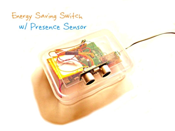
Have you ever met to this problem that urgently you have to go somewhere and you are try to call your wife or children to tell them about the problem but unable to call them due to some network error. I am sure on some point in life you have met with this type of condition or similar to it. In these case this audio messenger will be a lot helpful to you. It will give your friends or family member your message. I you want to give your family member messages on daily basis then also you can use it. It can also help you to improve your bad habits.
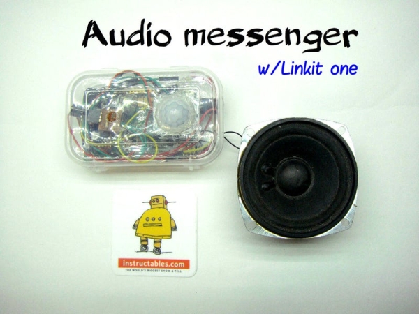
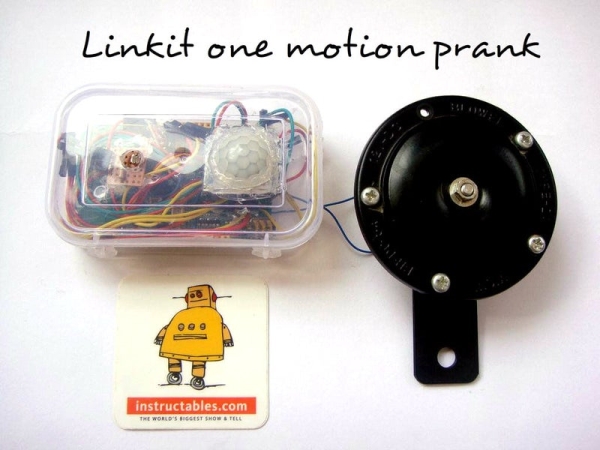
It works on a very simple principle. When any person pass from near to it or obstruct the laser beam, the voice message stored in the SD card is played through linkit one audio jack. To detect motion, a PIR motion sensor as well as a laser checker is used. The reason to use two sensor is that if motion sensor somehow fails to detect motion, laser checker is there to act as a backup plan. The length of audio message is decided by you. You have to save your voice or audio recoding in the SD card by the name “media1”.
For more cool projects, DIYs, electronic information visit and follow my facebook page Frozen solenoid.
PLEASE VOTE FOR ME IN THE CONTEST IF YOU LIKE IT.
Step 1: Gather Parts
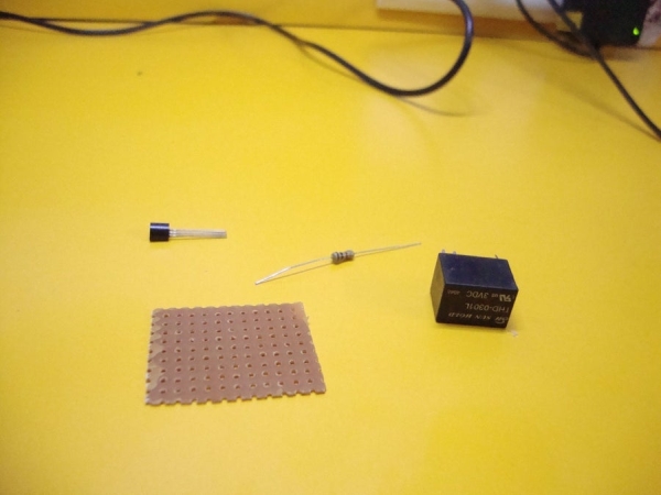
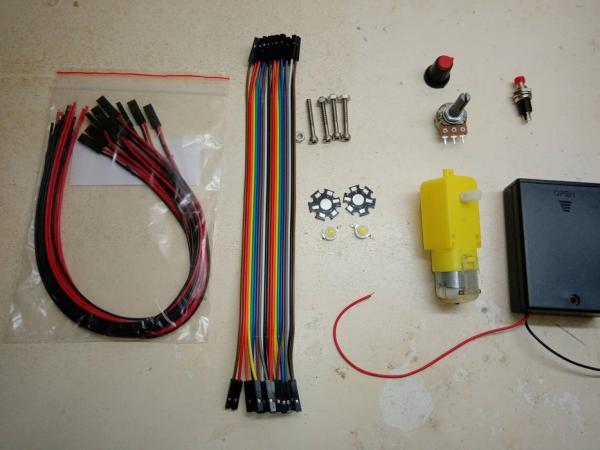
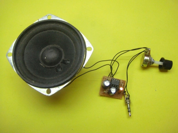
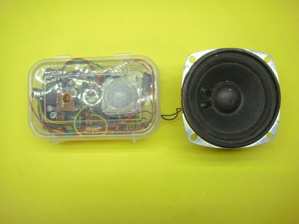
Here is the part list of this projects. Everything is easily available at online stores. Laser module can be bought easily from online store. You can buy a speaker or take it out from a old desktop speaker. Here is the list:
PARTS:
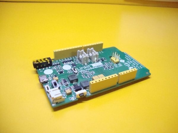
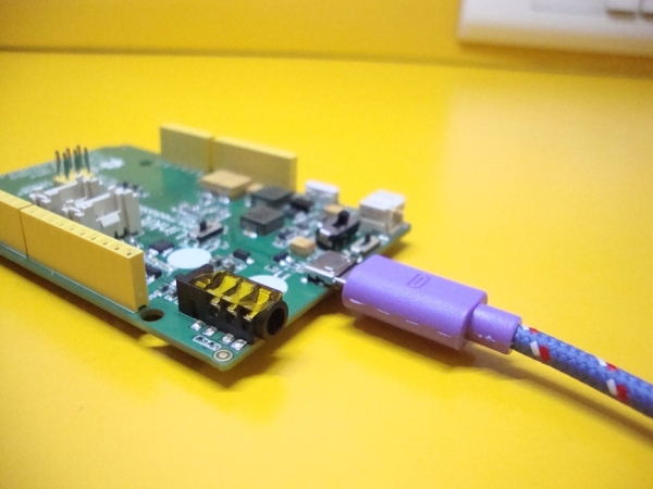
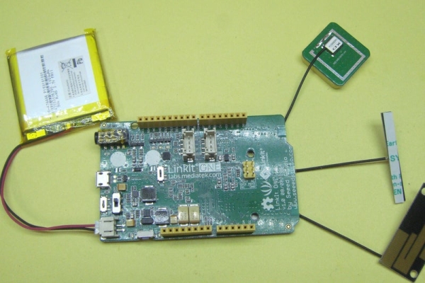
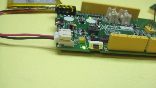
- Linkit one
- Motion sensor
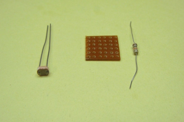
- LDR(Light dependent resistor)
- Laser module
- Speaker
- 10K resistance
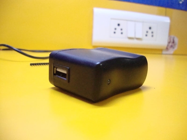
- 12V adapter
- LM386 audio amplifier IC
- 8-pin IC socket
- 10K potensiometer
- 2 X 220uf electrolytic capacitor
- 2 X 10ohms resistor
- 2 X 1K capacitor
- LED
- 3.5mm audio jack
- PCB
- 3V power supply to power your laser
- A battery for linkit one board
- A box
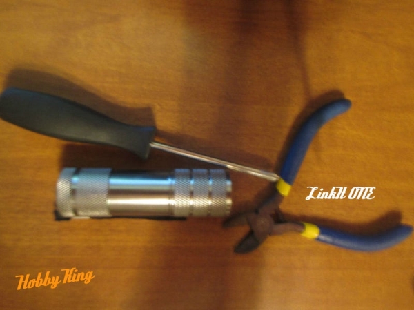
TOOLS:
- Soldering iron
- A dremel or something by which you can make holes in the box
- pliers
- Hot glue gun
MISCELLANEOUS:
- Ruler
- A marker
- Tape
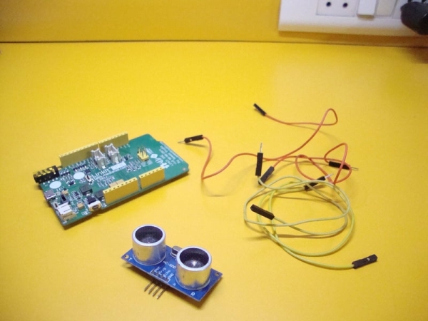
Step 2: Connecting Motion Sensor

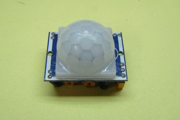
When a motion is detected, the horn attached to the linkit one board should start blowing. There are multiple ways to detect a motion but according to me the best way is to use a PIR motion sensor. You can use a infrared led motion sensor but it is not as much accurate in detecting motion as PIR motion senor is. This PIR motion sensor works on the principle of infrared radiation. A human body emits infrared radiation due to heat generated by various organs of the body. A change in infrared radiation trig the motion sensor and output pin of this sensor goes high. This is how a infrared motion sensor works. To know more visit my instructable linkit one sensor tutorial
I made a small shield for my sensor because it is not much breadboard friendly. You can use female to male jump cables but I prefer both side male. Connect your Motion sensor to your linkit one board as follow:
- vcc of sensor—–vcc of board
- gnd of sensor—–gnd of board
- Vout of sensor—–digital pin 8 of board
To check your motion sensor visit my instructable linkit one sensor tutorial whose link you can find above. Copy and paste the code given there. I also ,made a small shield for my linkit one power connector as it has only one vcc and gnd a number of connections to them are more.
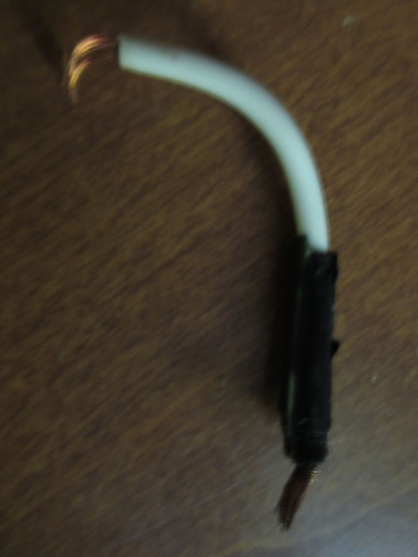
Step 3: Connecting the LDR
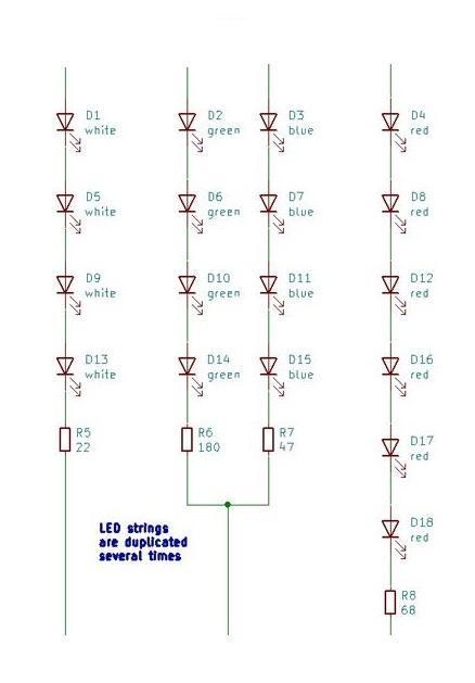
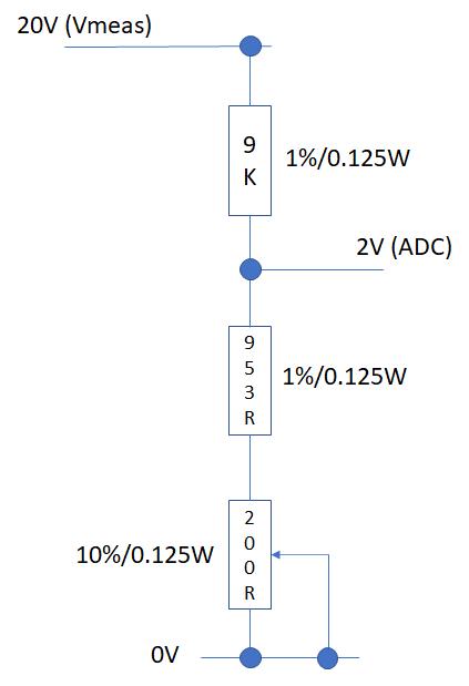
If a person is at a far distance or by chance our motion sensor fails to detect motion then their should be some backup plan which can detect motion a blow the horn. This laser trigger is for that only. The laser light get scattered a very little therefor it travel a very long distance in a straight path. A laser pointer is used here. The pointer of the laser light is on the LDR and when their is an obstruction in the path of laser light, the output of the LDR become low and the horn starts blowing. The LDR is connected to analog input of the linkit one board. Laser light is powered separately using a 3V battery pack. The circuit diagram is given above or follow these steps to connect your LDR to the board:
- One end of LDR—–vcc of Linkit one board
- Other end of LDR——Analog input 0 of linkit one board
- Short analog input 0 and gnd of the board using a 10K resistor
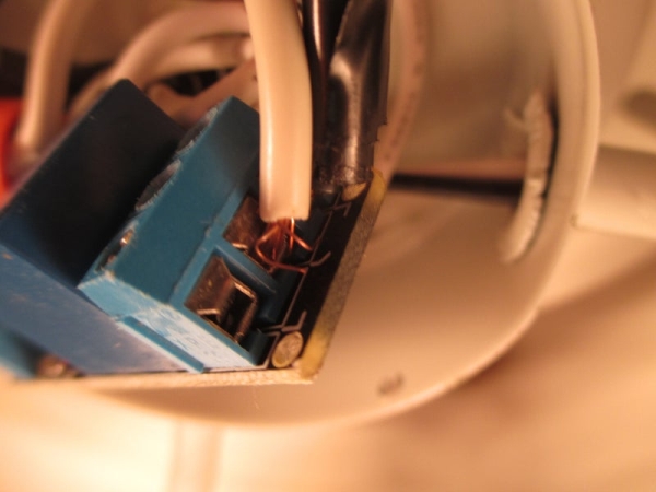
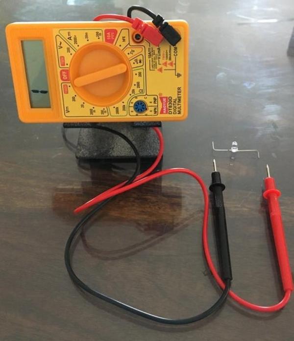
Connect the positive of the laser light to positive of the 3V battery pack with a switch in between and gnd of the battery pack to gnd of the laser light. Now you need to check what is the value send to your linkit one by
your sensor when laser pointer is on the sensor. To check upload this code code to your board and open serial monitor:
int laser_sensor=A0;
void setup()
{
Serial.begin(9600);
}
void loop()
{
Serial.print(“The value is:”);
Serial.println(analogRead(laser_sensor));
delay(1000);
}
Step 4: Prototyping the Amplifier Circuit
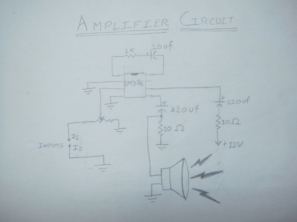
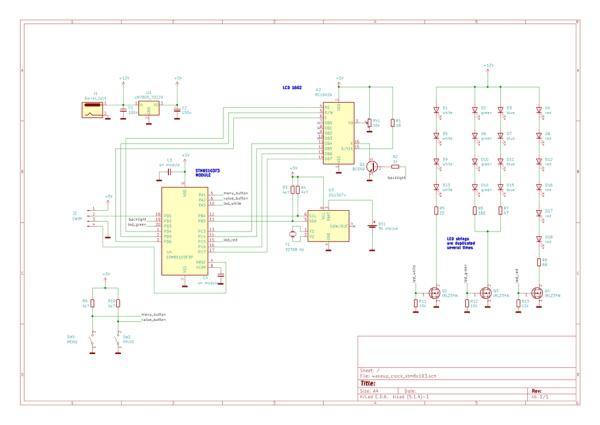
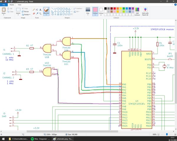
It is good to make the circuit on breadboard before soldering it on perfboard. It helps you to check the circuit as well as parts. If any part is not working properly, it is good to replace it now instead of doing that after you have soldered all the components on perfboard. Prototyping also helps you to memorize the circuit which minimizes the errors while making it on perfboard. For circuit diagram look at the images attache above. Prototype the circuit on breadboard, power on the amplifier and check whether all parts are working properly or not. Replace the part which is malfunctioning. Use the same adapter by which you would power your final products so as to check whether your adapter is capable of supplying the sufficient power to your amplifier or not.
CIRCUIT DIAGRAM GIVEN ABOVE.
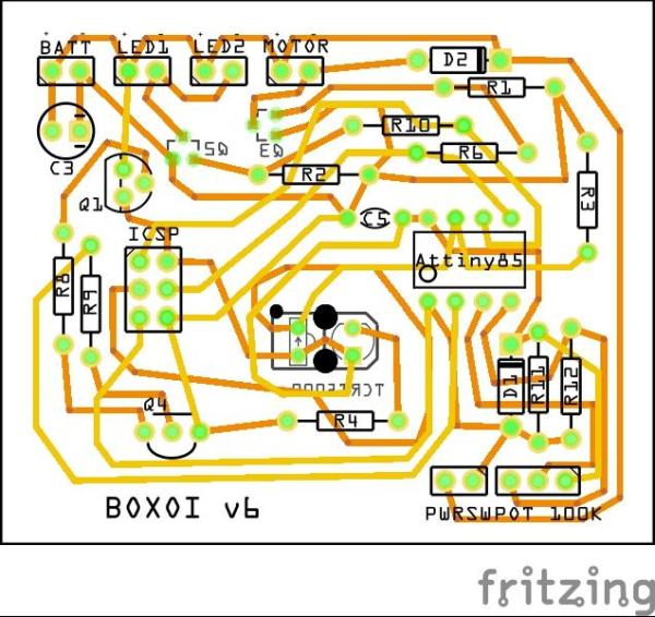
Step 5: Soldering the Amplifier Circuit
After prototyping the circuit, its time to make it on perfboard. Fetch a perfboard and start placing components components in it. Solder them properly so that they do not make any problem afterwards. This time do remember to use IC base because in case your IC stops working or malfunctions due to any reason, you can easily replace it. You can even cover your perfboard with white paper before soldering components in it. Be careful while soldering the components. Excessive heating can damage your components.
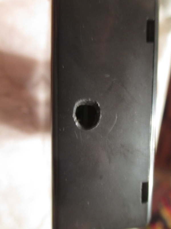
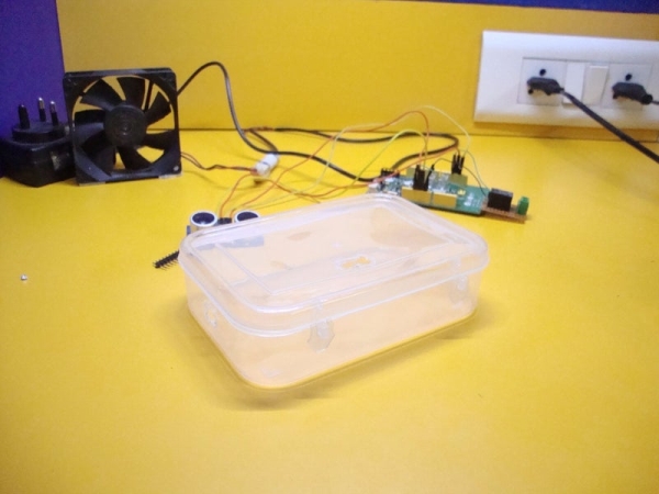
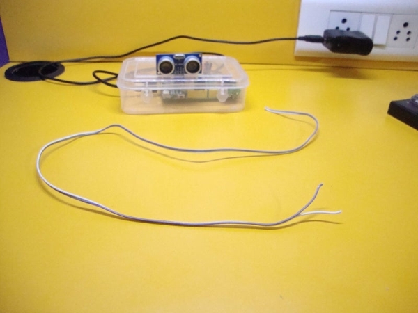
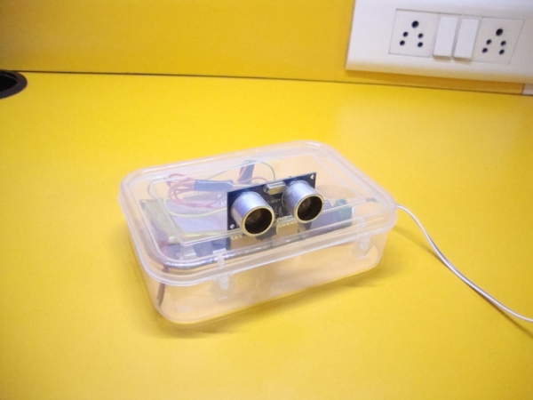
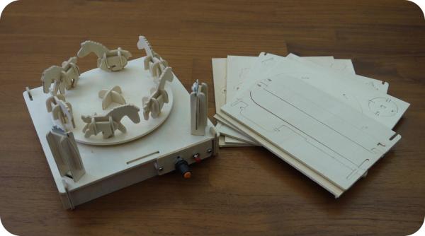
Step 6: Making a Enclosure
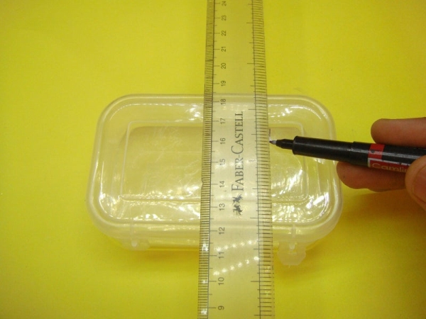
Now its time to make some holes. We would be making a box for our project. Pick up your box and start making the marks with the help of a marker and ruler for the holes of the component . You can use a drill machine to cut holes but a dremel would be better option. You have to make holes for the following things:
- Motion sensor
- A small hole from which laser pointer can enter the box
- A hole for the speaker wire
- A hole for the adapter jack
- A hole for the USB cable
- For a switch
You can cover the box with a white paper or color the box with you favorite color. You can stick stickers on your box to decorate it.
Step 7: Upload the Code
Now this is the time to upload the code to your linkit one board. This is the main step. After uploading the code remove the USB cable from linkit one board. Here is the code and after uploading the code move to the next step where we will hot glue our components with the box.
**********
//Code for audio messenger
//Made by Dushyanta
#include
#include
#include
int motion_sensor=8;
int laser_sensor=A0;
void setup() { Serial.begin(9600);
Serial.println(“Initializing\n”);
LAudio.begin();
LSD.begin();
LAudio.setVolume(10);
LFile rootDir=LSD.open(“/”,FILE_READ);
delay(5000);
LAudio.playFile(storageSD,”media1″);
delay(30000);
}
void loop() { if(digitalRead(motion_sensor)==HIGH) { LAudio.playFile(storageSD,”media1″); } else if(analogRead(laser_sensor)>512) //change 512 from your value { LAudio.playFile(storageSD,”media1″); } delay(50);
}
**********
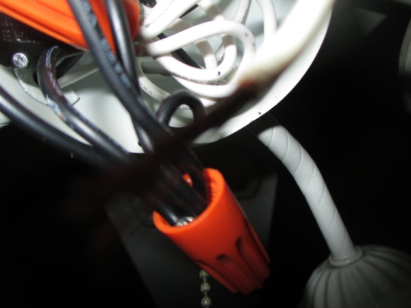
Step 8: Hot Glue Everything
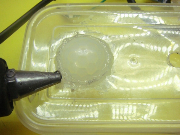
Heat up your glue gun because its time to stick your components. Don’t skip this step as it is one of the most important steps of this project. You can use double sided tape to stick you board to the box but the better option would be to use a hot glue gun. It will not damage your board. Stick your linkit one board to the box and don’t forget to apply some glue at the point from where the wire is going out to the speaker. Glue the LDR in front of the small hole from where the laser beam would enter the box.
Step 9: Checking

Now its time to check the project. This project requires about 30 to 40 seconds to start. I can make a code which can immediately start the power after the power supply is turned on but the motion sensor used here requires about 30 seconds to work properly. Instead of 30 seconds, I gave a pause of 35 seconds so that there is no chance of motion sensor not working properly. In that gap of 35 seconds we would be checking our sound system. 5 seconds after the power power supply is turned on, the audio file named “media1” will be played. “media1” is the file which will be played when the motion is detected. So the audio file you want to play when the motion is detected should be named as “media1”. If whole message is spoke perfectly, then your sound system is working. After 35 seconds your project will be ready to use. When a person pass from near or obstruct the path of laser light,the audio file “media1” would be played.
Step 10: Done!!
Now use this messenger to give messages to your loved ones. Use it on festivals to give greetings to your loved ones when they pass from near to it. Use it in urgent conditions to give messages.
This is the end of this instructable. Hope you like it. If there is any query, you can comment below or you can mail me or can ask me on my facebook page Frozen solenoid. For more cool projects,follow me. THANK YOU
PLEASE VOTE FOR ME IN THE CONTEST.
Source: Linkit One Audio Messenger